
Subscribe to Our Youtube Channel
Related Manuals for Sanwa PC20TK


Summary of Contents for Sanwa PC20TK
- Page 1 MULTIMETER PC20TK Assembling Training for Digital Multimeter Instruction Manual for Assembling and Operation Procedures...
-
Page 2: Table Of Contents
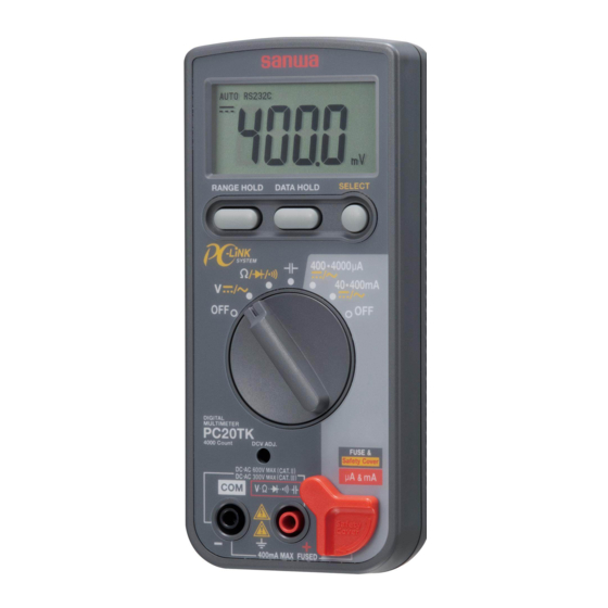
Introduction Thank you very much for purchasing Sanwa Model PC20TK Digital Multimeter Kit. The PC20TK is a digital multimeter kit that we have developed for educational use through a wealth of our experiences and achievements. Although primarily designed as a kit, this product provides eight modes including voltage and current, as well as high durability, allowing you to use it for a broad range of purposes. -
Page 3: Warnings For Safe Use Of Multimeter
4. Do not try to measure a line (e.g., to a motor) where induced voltage or surge voltage may occur, because the maximum overload input value might be exceeded. 5. Do not use the PC20TK if its main body or test lead is damaged or broken. 6. Do not use the PC20TK with its case removed. -
Page 4: Using The Pc20Tk
5. If you connect the PC20TK to your PC by using the optionally available PC link (software) and PC link cable, changes in electric quantity can be displayed as values or graphs on the PC monitor. -
Page 5: Specification
∆ ∑ system Operating system Readout 4,000 counts (with unit and symbol) Mode selection Auto or manual; only the auto mode is available for electric capacitance. Overflow value The O.L. mark appears (except in the 750 V range for both DC and AC) Polarity The "-"... -
Page 6: Explanation Of Functions
(true value) was measured in the 400 VAC range of the PC20TK. The accuracy of the 400 VAC range of the PC20TK is ± (1.5 %rdg + 5dgt). 1dgt in the 400 V range is equivalent to 0.1 V. Hence, (±1.5 %×106.6 V) + (±0.1 V×5) = (±1.6 V) + (±0.5 V) = ±2.1 V... -
Page 7: Preparations For Measurement
This indicates that the measured values are output as digital signals through the LED located on the rear of the PC20TK (see 9 on page 10). The following explanation is made assuming that the auto mode is active:... - Page 8 Warning: The O.L. mark does not appear even if overvoltage of 750 V or more is applied to the input connector. A measurement error occurs if non-sinusoidal voltage is measured, because the PC20TK operates with the mean value. The accuracy is warranted in the frequency range of 40-400 Hz.
- Page 9 3. Measuring resistance ( Ω ) (see Fig. 2-3) This functional mode is used to measure the resistance of a resistor, a circuit or a circuit component. Warning: Measuring any live part is not possible and such an attempt is dangerous. An error will result if you make a measurement while touching the test pins.
- Page 10 5. Continuity test ( ) test (see Fig. 2-5) This functional mode is used to check electrical continuity of wiring, a switch or other. Warning: Checking any live part for continuity is not possible and such an attempt is dangerous. The buzzer sounds when the resistance at the check point is approximately below the range of 10-60 Ω.
- Page 11 Warning: Be sure to measure current in series with the load. An attempt to measure current in parallel with the load is dangerous as large current would flow through the PC20TK. If a current range is connected, its internal resistance may cause a smaller current value than the actual one to be displayed.
- Page 12 * Connecting procedure (1) Open the stand located on the rear of the PC20TK. (2) Attach the cable box to the rear case of the PC20TK by using the screw provided with the cable box. (3) Connect the cable connector to the PC.
-
Page 13: Replacing The Fuse And Batteries
(2) Avoid using the PC20TK in a place exposed to high or low temperature or high humidity. (3) If the PC20TK is not used for a long period of time, store it with the built-in batteries removed. (4) The PC20TK is neither dust-proof nor drip-proof. -
Page 14: Basic Knowledge Of Digital Multimeter
[3] Basic Knowledge of Digital Multimeter 3-1 Analog vs. digital Quantities are roughly classified into analog quantities and digital ones. Analog quantities represent quantities having continuous intensity, such as time, length, weight, electric voltage and current. Digital quantities mean quantities having discontinuous intensity, such as 1, 2 and 3 counted for things. -
Page 15: Construction Of Digital Multimeter
Fig. 3-2: Block diagram of digital multimeter A digital multimeter generally allows for measuring 5 kinds of electric quantities: DC voltage (DCV), AC voltage (ACV), DC current (DCA), AC current (ACA), and resistance (Ω). The PC20TK also allows for performing a diode test ( ) and measuring electric capacitance ( ). -
Page 16: Working Of Input Signal Conversion Section
3-4 Working of input signal conversion section The following typical example is assumed to explain how each input signal is processed to obtain DC voltage that will be applied to the A/D conversion section. 1. DC voltage (DCV) For measurements of DV voltage, the user selects the most suitable range in accordance with the voltage level to be measured. -
Page 17: Working Of A/D Conversion Section
The available A/D conversion methods include the integration, comparison, and ∆ ∑ methods. The PC20TK uses the ∆ ∑ method. In this paragraph, however, the double integration method is explained because it is used for a large number of digital multimeters and theoretically easier to understand. - Page 18 Output voltage Input voltage Input Output voltage Vo voltage amplifier The slope of the line for Vo becomes larger as Vi increases. Fig. 3-10: Integration circuit • Comparator (0-detector) The comparator has an inverting input terminal (negative) and a non-inverting input terminal (positive).
- Page 19 2. Principle of double integration circuit : Input voltage under measurement : Integration period (constant) Vref : Reference voltage (constant) : Reverse integration period Given the above conditions, the output voltage of the integration circuit is 0 V at the end point of reverse integration (point t in Fig.
- Page 20 (14) The same sequence is repeated again from the beginning. The number of times when this repetition is made per second is called a sampling rate. The PC20TK does not use the double integration method, but its sampling rate is 3 times per second.
- Page 21 Output voltage Point A Vo of integration circuit Integration circuit Input selection switch Comparator Input voltage Controls turning ON/OFF SW1 and Reset signal Switch selection signal detection signal Reference Control circuit Gate opening signal voltage Vref Gate Reset detection signal signal Latch signal Clock pulse...
-
Page 22: Assembling
[4] Assembling 4-1 Soldering Soldering is important work in assembling the multimeter. Incomplete soldering of parts can cause a problem by causing the multimeter to fail to operate or malfunction during use. Solder is alloy with a low melting point, which uses lead and tin as main ingredients to electrically and mechanically connect metal to metal (a component to a component). -
Page 23: Precautionary Instructions For Assembling
2. Chip component 1 Apply a small amount of preliminary solder to one Solder end of land. Solder 2 Amount a component and press it with your fingers. Solder 3 Melt the preliminary solder with the soldering iron tip to solder the component. - Page 24 [Example of identifying square chips: 22 kΩ] 1st numeral 2nd numeral 3rd numeral Multiplier 1st numeral 2nd numeral Multiplier Fig. 4-3(b): Example of identifying resistors 2. Example of identifying capacitors (some capacitors have no identification) Rated voltage symbol Rated voltage symbol 1st numeral 1st numeral 2nd numeral...
-
Page 25: Preparations For Assembling
4-5 Preparations for assembling 1. Tools (supply the tools shown in the following tables) Check Name Remarks Check Name Remarks Soldering iron 15 to 20 W Phillips screwdriver Medium size Tweezers Small size Slotted head screwdriver for adjustment use: small size Nipper Small size (Blade: 2-2.2 mm in width and 0.4... -
Page 26: Mounting And Wiring Components To Printed Circuit Board (Large)
4-6 Mounting and wiring components to printed circuit board (large) 1. Mounting components to the component mounted surface: through Be sure to check the polarities of the diode and then solder it. Check Order Name of component : Quartz oscillator After soldering, cut D5 : Diode off the lead wire of... - Page 27 2. Mounting components on silk-screen printed surface (part 1): through • Insert the lead wires of each component into the specified holes in the printed circuit board and then solder them on the opposite mounted surface. • Be sure to check the polarities of the buzzer. No components other than the buzzer have polarities.
- Page 28 3. Mounting components to silk-screen printed surface (part 2): through • Solder the battery terminals, the fuse folders and the lead wire on the opposite side. • Insert the two fuse folders into the printed circuit board with attention to their polarities (the stoppers are positioned mutually outward).
-
Page 29: Wiring The Printed Circuit Board (Small) (Fig. 4-9)
4-7 Wiring the printed circuit board (small) (Fig. 4-9) Insert the lead wires from the printed circuit board (large) complete with the components soldered into the land holes marked with the corresponding symbols of the printed circuit board (small), and then solder them (3 places of A, B and COM). - Page 30 Fig. 4-12 Conductive surface (same as on the Mount the zebra-striped connector onto the opposite side) Rubber switch stepped part of the LCD that is fit into the Zebra-striped connector panel. Caution: During work, ensure that no foreign matter attaches to the conductive surface. Mount the rubber switch onto the panel.
-
Page 31: Assembling The Rear Case
4-10 Assembling the rear case Warning label Fig. 4-16 Through- (remove backing screw-hole paper) Attach the warning label after removing its backing sheet. Dial A Round rubber foot Remove the round rubber foots from the (semitranslucent, purple-colored) mounting paper board and firmly set them (2 Rectangular places). -
Page 32: Adjustments
After the adjustment, 2. Order of adjustments close the adjustment hole with the oval seal. The PC20TK is designed to show any of the readings within the accuracy shown in "2-3 Specification" after the DCV adjustment has been completed. Fig. 4-19:... -
Page 33: Layout Of Components On The Mounting Surface
4-13 Layout of components on the mounting surface Fig. 4-20: Layout of component on the mounting surface... -
Page 34: Circuit Diagram Of The Pc20Tk
4-14 Circuit diagram of the PC20TK Fig. 4-21: Circuit diagram... -
Page 35: Inspection And Calibration
(or reading the value displayed on the PC20TK against the standard input). Enter the calibration result as in the example of completing the table for test results on page 34. Use the test result form on page 37 or its photocopy. -
Page 36: Error Rate
5-2 Error rate Error rate is represented as the percentage ratio of reading M on the unit under measurement (the PC20TK) minus true value T (reading on the standard) to true value T. M−T = - × 100 (%) 5-3 Example of completing the table for test results... -
Page 37: Table For Test Results
Table for Test Results Model :PC20TK Tested on : Serial No. :2031234 Test conditions : Temperature °C ; relative humidity : Frequency of AC voltage and current Tested by: Reading M on Reading T on Functional mode PC20TK standard Error rate... -
Page 39: Calculation Problems For Input Circuit
[6] Calculation Problems for Input Circuit 6-1 Voltage measurement circuit 1. When the input voltage is 1000 V in Fig. 6-1, find R in Ω with which 1 V is obtained as the standard output (uniform different units of resistance for calculation). Assume that the input resistance of the LSI connected to the output connector is infinite ( 990 k Input voltage... - Page 40 6-2 Current measurement circuit When the input current is 400 mA in Fig. 6-3, find electric shut resistor R in Ω with which the output voltage of 400 mA is obtained. Create an equation to find R. Assume that the input resistance of the LSI connected to the output connector is infinite ( Output voltage Input voltage...
-
Page 41: Overview Of Troubleshooting
[7] Overview of Troubleshooting First check that the printed circuit boards are properly snapped into the panel and that the dry cells are placed in correct polarities. • The dry cells have run out; the battery terminals were soldered improperly or in a deformed shape. •... -
Page 42: After-Sale Service (8-1)
In such a case, it is recommended that a new product be purchased. The transportation charges for sending your PC20TK to us and returning it to you are to be borne by you along with the repair charge. 4. Address for sending your PC20TK In order to ensure the safe transportation of the PC20TK, place it in a box having volume of at least 5 times the product size and fill the space with sufficient pad or filler. - Page 43 About safekeeping Caution 1. To keep the panel or case clean, please wipe it with a dry, soft cloth. Do not use thinner or alcohol- based solvents because these can harm the finish. 2. Please do not leave this unit next to any direct source of high heat (like a soldering iron). 3.
- Page 44 Sanwa Electric Instrument Co., Ltd. Head Office: Dempa Building, 2-4-4 Sotokanda, Class Chiyoda-ku, Tokyo 101-0021 Japan Phone: 81-3-3253-4871 Osaka Sales Office: 2-7-2 Ebisu-nishi, Naniwa-ku, Name Osaka City 556-0003 Japan Phone: 81-6-6631-7361 03-1308 2040 2040...
Need help?
Do you have a question about the PC20TK and is the answer not in the manual?
Questions and answers