Table of Contents
Advertisement
Advertisement
Table of Contents

Related Manuals for Sanwa PC7000


Summary of Contents for Sanwa PC7000
- Page 1 PC7000 DIGITAL MULTIMETER INSTRUCTION MANUAL...
-
Page 2: Table Of Contents
Table of Contents [1] SAFETY PRECAUTIONS Explanation of Warning Symbols ………………………… 1 Warning Instructions for Safe Use ………………………… 2 Overload Protection ………………………………………… 3 [2] APPLICATIONS AND FEATURES Applications ………………………………………………… 4 Features ……………………………………………………… 4 [3] Parts Identification Multimeter and Test Leads ………………………………… 5 Display ………………………………………………………... - Page 3 Calibration ………………………………………………… 56 Battery and Fuse Replacement ………………………… 57 Storage …………………………………………………… 58 [7] AFTER-SALE SERVICE Warranty and Provision ………………………………… 59 Repair ……………………………………………………… 59 SANWA web site ………………………………………… 60 [8] SPECIFICATIONS General Specifications …………………………………… 61 Measuring Range and Accuracy ……………………… 63...
-
Page 4: Safety Precautions
*Before use, read the following safety precautions. This instruction manual explains how to use your digital multimeter PC7000. Before using, read through this manual to reduce the risk of fire , electric shock, and/or injury. And save it together with the product so that you can refer to the manual as necessary. -
Page 5: Warning Instructions For Safe Use
1-2 Warning Instructions for Safe Use WARNING 1. Do not use the instrument if the meter or test leads look damaged. 2. Be sure to use the specified fuse. Neither use unspecified fuse nor short-circuit the fuse holder. 3. Do not apply higher voltage or current than the max. ratings by each function. -
Page 6: Overload Protection
1-3 Overload Protection Measuring Function Max. Rated Input Overload Protection Terminal 「 」, 「 」 1000V dc/ac 1050V rms, 1450V peak 「 」 「 」 「 」 5V dc/ac Do not apply 「 」, 「 」 any voltage or 600Vrms current. -
Page 7: Applications And Features
[2] APPLICATIONS AND FEATURES 2-1 Applications This instrument is a portable digital multimeter designed to measure light electric circuits. The instrument offers not only measurements for small communication equipments, home electric appliances, output from a wall socket, and many batteries, also circuit analyses with additional functions. -
Page 8: Parts Identification
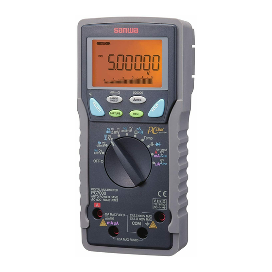
[3] Parts Identification Light shielding magnet cap 3-1Multimeter and Test Leads Optical communication unit connector LCD display Range hold button Select button Crest capture button Relative button MAX/MIN/AVG recording button Data hold button Power/ Function selector Measuring terminal for A Measuring terminal for mAµA Stand... - Page 9 How to detach the light shielding magnet cap Light shielding magnet cap ⇒ Attached Turn the light shielding magnet cap counterclockwise to detach. An application of the light shielding magnet cap Attach the light shielding magnet cap DMM body with side touched to the wall.
-
Page 10: Display
3-2 Display ⑨ ⑪ ⑧ ⑱ ⑮ ⑦ ⑤ ⑩ ⑫ ⑥ ⑬ ⑭ ⑮ ① ⑯ ② ⑰ ③ ④ ① Main display ② Unit of readings for main display ③ Polar character for main display ④ Analog bar graph ⑤ Sub display ⑥ Unit of readings for sub display ⑦ Polar character for sub display ⑧ Low battery voltage indicator ⑨ Auto range mode indicator... -
Page 11: Description Of Functions
[4] DESCRIPTION OF FUNCTIONS 4-1 Power Switch/Function Selector Turn the switch to turn on/off the power and select a measuring function. All segments of the LCD display will be turned on for 1 second after power-on, and then the meter will be ready to use. Note: The push buttons between the display and the function selector work differently depending on how long you press. -
Page 12: Low Battery Indication
4-2-2 How to disable the Auto Power Saving Press the SELECT button while turning the meter power on. Release the SELECT button after is turned off. (All segments of the display turn on after power-on.) Then the meter will be ready to use. Turn the power switch OFF and then back on to resume. -
Page 13: 500000-Count Display Mode
「 」 ・ : [ ] ⇔ [ 「 」 ・ : When a test lead is not connected to measuring terminal [ m /%4 ∼ 20mA ] ⇒ [ m / m ] ⇒ [ /m ] ⇒ [ m /Hz ] ⇒ [ m /%4 ∼ 20mA ] … When a test lead is connected to terminal ] ⇒... -
Page 14: Range Hold
4-6 Range Hold Press the RANGE HOLD button to select manual-ranging, and the meter will remain in the range it was in. ( turns off.) In the manual-ranging mode, press the button again to step through the ranges. Select an appropriate range making sure units and decimal point positions. -
Page 15: Pc (Personal Computer) Interface
4-9 PC (Personal Computer) Interface The instrument equips with an optical isolated interface port at the meter back for data communication. KB-USB7, dedicated USB optical communication unit (separately available), and PCLink7, dedicated software, allow you to transfer real time readings and internally logged data to your PC. -
Page 16: Test Leads Improper Connection Warning
4-10 Test Leads Improper Connection Warning The meter beeps as well as displays “InErr” to warn the user against possible damage to the meter due to test leads improper connections to the , or measuring jacks when other function (like voltage function) is selected. (Temperature measurement function is an exception.) Note: “InErr”... -
Page 17: Relative Measurement
4-13 Relative Measurement Press the △ REL button to activate the relative measurement △ indicator turns on. The relative measurement mode and mode offsets the meter to display relative values against a reference. The meter displays its readings subtracting the reading at the moment the △... - Page 18 Root Mean Average Crest Form 0 to PEAK Square Value Value Factor Factor Input Waveform Vrms Vavg Vp/Vrms Vrms/Vavg π − − √ − √ √ π Sinusoidal π 2π wave =0.707Vp =0.637Vp =1.414 =1.111 Square π 2π wave − −...
-
Page 19: Measuring Procedure
[5] Measuring procedure 5-1 Pre-operational Check WARNING 1. Do not use the instrument if the meter or test leads look damaged. 2. Make sure the test leads and the fuse are not broken. CAUTION Make sure the low battery indicator is off after power-on. Replace the battery with new one if the indicator is on. - Page 20 START Damaged Meter/Test leads damaged? Looks OK ① Connect the red plug of the test lead to measuring terminal and the black one to the COM terminal. ② Set the function selector to ③ Press the SELECT button to select the continuity check ( ④...
-
Page 21: Variable Frequency Drive (Vfd) Ac Voltage ( )/Frequency (Hz) Measurement
「 」 (Max. rated input voltage: 1,000V dc/ac) AC Voltage ( )/Frequency (Hz) simultaneous measurement for Variable Frequency Drive (VFD) through the Low-pass filter (LPF) WARNING 1. Do not apply any input signal exceeding the max. rated input voltage. 2. Do not switch the function selector while measuring. 3. - Page 22 / Hz Hz / ― 19 ―...
- Page 23 Note: Press the SELECT button to alternately change the display style. By default, voltage is always set at manual-range 500V to best cope with most Variable Frequency Drives (VFD) measurements. Press the RANGE button to select other ranges only when needed.
-
Page 24: Ac Voltage ( ), Decibel (Dbm)/Frequency (Hz)
「 」 (Max. rated input voltage: 1,000V dc/ac) AC Voltage ( ), Decibel (dBm) / Frequency (Hz) simultaneous measurement WARNING 1. Do not apply any input signal exceeding the max. rated input voltage. 2. Do not switch the function selector while measuring. 3. - Page 25 Hz / / Hz Indicaion in dBm: After pressing the SELECT button to change the function to the dBm measurement from the ACV measurement, and after turning on the power of this multimeter, the latest reference impedance will be displayed before displaying the dBm readings. Press (RANGE) button to select different reference impedance of 4, 8, 16, 32, 50, 75, 93, 110, 125, 135, 150, 200, 250, 300, 500, 600, 800, ―...
- Page 26 dBm/Hz RANGE Frequency measurement (Hz) Range Frequency range Input sensitivity (Sine wave) 10.00Hz ∼ 200.0kHz 5.0000Vac 0.5V 50.000Vac 10.00Hz ∼ 100.0kHz 500.00Vac 10.00Hz ∼ 10.00kHz 1000.0Vac 500V The display style of [ /Hz ] shows the bar graph. As a normal condition, non-connected test leads may cause unstable readings.
-
Page 27: Measurement
「 」 (Max. rated input voltage: 1,000V dc/ac) ・ DC Voltage( ) measurement ・ DC Voltage( )/AC Voltage( ) simultaneous measurement ・ DC+AC voltage( )/AC Voltage( ) simultaneous measurement WARNING 1. Do not apply any input signal exceeding the max. rated input voltage. 2. - Page 28 (500000-count) 1Sec. ― 25 ―...
- Page 29 Note: Press the 500000 ( Δ REL) button for 1 second or more to turn the 500000-count display mode on. It is available to single display DC Voltage function ranges. Measuring speed is reduced to 1.25 times per second. To turn the 500000-count display mode off, press the 500000 ( Δ...
-
Page 30: Dc Voltage (M )/Ac Voltage ( M )/ Dc+Ac Voltage (M ), Logic-Level Frequency ( Hz) And Duty Cycle ( D%) Measurement
「 」 (Max. rated input voltage: 10V dc/ac) ・ DC voltage (m ) measurement ・DC Voltage (m )/AC Voltage(m ) simultaneous measurement ・DC+AC Voltage (m )/AC Voltage (m ) simultaneous measurement ・ Logic-level frequency ( ) measurement ・ Duty cycle ( D%) measurement WARNING 1. - Page 31 3) Measuring procedure ① Connect the red plug of the test lead to the VHz measuring terminal and the black one to the COM terminal. ② Set the function selector to ③ Press the SELECT button to select a function you want to perform.
- Page 32 ― 29 ―...
- Page 33 Note: ・ The display style of [m /m ], [m ], [ or [ D%] does not show the bar graph. ― 30 ―...
-
Page 34: Measurement
「 」 5-6 (Max. rated input voltage: 500mV dc/ac) ・ AC Voltage (m ), Decibel (dBm) / Frequency (Hz) simultaneous measurement WARNING 1. Do not apply any input signal exceeding the max. rated input voltage. 2. Do not switch the function selector while measuring. 3. - Page 35 Hz / m / Hz Indicaion in dBm: After pressing the SELECT button to change the function to the dBm measurement from the ACV measurement, and after turning on the power of this multimeter, the latest reference impedance will be displayed before displaying the dBm readings. Press (RANGE) button to select different reference impedance of 4, 8, 16, 32, 50, 75, 93, 110, 125, 135, 150, 200, 250, 300, 500, 600, 800, ―...
- Page 36 dBm/Hz Note: Frequency measurement (Hz) Range Frequency range Input sensitivity (Sine wave) 10.00Hz ∼ 200.0kHz 500.00mVac 100mV The display style of [m /Hz] shows the bar graph. As a normal condition, non-connected test leads may cause unstable readings. Manual trigger level selection on Hz reading is not available in this function.
-
Page 37: And Conductance (Ns) Measurement
「 」 5-7 (Do not apply any voltage or current.) ・ ・ Conductance (nS) measurement ・ Continuity check ( WARNING Do not apply any voltage or current to the measuring terminals. CAUTION In the case of high resistance measurement, readings may be unstable due to external inductive influence. - Page 38 3) Measuring procedure ① Connect the red plug of the test lead to measuring terminal and the black one to the COM terminal. ② Set the function selector to ③ Press the SELECT button to select a function you want to perform.
- Page 39 Note: ・ [nS] function does not show the bar graph. ・ To avoid external noise influence, shield the object to measure with COM potential. Measurements with finger-touched test pins may cause some errors being influenced by human body conductance. ― 36 ―...
-
Page 40: Temperature Measurement
「 」 5-8 (Max. rated input voltage: 50mV dc) ・ Temperature measurement ( ℃ ) or ( ( For K-type thermocouple) WARNING 1. Pay attention in order to avoid risk of burn depending on the object temperature or measuring environment. 2. - Page 41 Temp Temp Note: Temperature function does not show the bar graph. The provided K-type thermocouple (K-250PC) is a polar device. Connect the device to the meter properly. The range of K-250PC is -50 ℃ to 250 ℃ . Separately available K-type adapter (K-AD) allows you to use other international standard mini plug thermocouples.
-
Page 42: Capacitance ( ) Measurement, Diode ( ) Test
「 」 5-9 (Do not apply any voltage or current.) ・ Capacitance ( ) measurement ・ Diode ( ) test WARNING 1. Do not apply any voltage or current to the measuring terminals. 2. Measuring live circuit may damage the meter. 5-9-1 Capacitance ( ) measurement CAUTION... - Page 43 Note: ・Capacitance function does not show the bar graph. ― 40 ―...
- Page 44 5-9-2 Diode ( ) test What to measure (Diode test): Judging the diode (Good or defective) Measuring procedure ① Connect the red plug of the test lead to measuring terminal and the black one to the COM terminal. ② , then press the SELECT Set the function selector to button to select the diode test.
- Page 45 Reverse biased test Forward biased test Note: ・Open circuit voltage between the measuring terminals: <3.5V dc ・Test current: 0.4mA (typical) ・Diode test function does not show the bar graph. ― 42 ―...
-
Page 46: Dc Current ( )/Ac Current ( )/Dc+Ac Current ( ), Ac Current ( )/ Frequency (Hz), And %4 ~ 20Ma Measurement
「 」 「 」 , 5-10 DC current (m ,µ , ) measurement AC current (m , µ )/Frequency(Hz) simultaneous measurement , µ , , µ DC current (m )/AC current (m simultaneous measurement , µ , , µ DC+AC current (m )/AC current (m simultaneous measurement... - Page 47 5-10-1 Current (mA/µA)/%4 ∼ 20mA measurement (m , m , m , µ , µ , µ Max. rated input current 500mA dc/ac) 1) What to measure m /%4 ∼ 20mA: Instrumentation loop current m , µ (DC current): DC circuit current m , µ...
- Page 48 m /%4 ∼ 20mA m / m Note: In the %4 ∼ 20mA measurement, loop-current percentage is indicated, being set at 4mA=0% and 20mA=100%. ― 45 ―...
- Page 49 m / Hz m / m ― 46 ―...
- Page 50 µ / µ µ ― 47 ―...
- Page 51 µ / Hz µ / µ Note: Measuring Frequency (Hz) Frequency range Range Input sensitivity(Sine wave) 500.00µA 50µA 5000.0µA 500µA 10.00Hz ∼ 10.00kHz 50.000mA 500.00mA 50mA ― 48 ―...
- Page 52 5-10-2 Current (A) measurement ( , , Max. rated input current AC 10A dc/ac ) 1) What to measure (DC current): DC circuit current (AC current): AC circuit current (DC current component / AC current component) (DC/AC superimposed signal current / AC current component) Hz (Frequency): Measuring current frequency 2) Measuring ranges...
- Page 53 ― 50 ―...
- Page 54 / Hz Note: ・ > 6A: Cool down more than 3 minutes after measuring 1 minute. < 6A Continuable Measuring Frequency (Hz) Frequency range range Input sensitivity (Sine wave) 5.0000A 10.00Hz ∼ 3.000kHz 10.000A ― 51 ―...
-
Page 55: Measurements With Separately Available Accessories
5-11 Measurements with Optional Products WARNING 1. Do not apply any input exceeding max. rated input for the separately available accessories. 2. 2. Do not switch the function selector while measuring. CAUTION To make measurements of consumption current for home appliances using a current probe, use a line separator as shown in the drawing below. - Page 56 ① Connect the red plug of the current probe to the V measuring terminal and the black one to the COM terminal. ② Set the function selector to , then press the SELECT button to select [ /Hz ]. ③ Press the RANGE button to set the 5.0000V range. ④...
- Page 57 [m ]. The 500.00mV range will be set. To make AC current measurement (ACA), set the function selector to and press the SELECT button to select /Hz]. The 500.00mV range will be set. ③ Set the range selector knob on the current probe to the 20A range or 200A range.
- Page 58 ③ Set the range selector knob on the current probe to the 30A range or 300A range. *Before making DC current measurement, turn the Center Adjuster knob to make the reading zero. ④ Open the clamp jaws of the clamp probe and clamp the wire to measure.
-
Page 59: Maintenance
[6] MAINTENANCE WARNING 1. The followings are important to safety. Read this manual throughly to maintain the instrument. 2. Calibrate and inspect the instrument at least once a year to ensure safety and maintain its accuracy. 6-1 Simple Examination 1) Appearance Check for damaged appearance by dropping down and so on. -
Page 60: Battery And Fuse Replacement
6-3 Battery and Fuse Replacement WARNING 1. Do not open the rear case with live measuring terminals to avoid electric shock. Also, make sure the meter power is OFF, before starting replacement. 2. Be sure to use the specified fuse. Neither use unspecified fuse nor short-circuit the fuse holder. -
Page 61: Storage
Rear case Battery door Battery Fuse 0.63A/500V φ6.3×32mm Breaking capacity : 50kA Part number : F1198 Screw for the battery door Fuse 12.5A/500V φ6.3×32mm Breaking capacity : 20kA Part number : F1199 6-4 Storage CAUTION 1. The panel and case are not resistant to volatile solvents. Do not wipe out with solvents or isopropyl alcohol. -
Page 62: After-Sale Service
(1) year from the date of purchase. This warranty policy is valid within the country of purchase only, and applied only to the product purchased from Sanwa authorized agent or distributor. Sanwa reserves the right to inspect all warranty claims to determine the extent to which the warranty policy shall apply. -
Page 63: Sanwa Web Site
An instrument sent to Sanwa / agent / distributor without above information will be returned to the customer. Note: 1) Prior to requesting repair, please check the following: Capacity of the built-in battery, polarity of installation and discontinuity of the test leads. -
Page 64: Specifications
[8] SPECIFICATIONS 8-1 General Specifications Operation Delta-sigma modulation method 50,000 counts: DCV , ACV , DCA, ACA, Resistance 500,000 counts: DCV 99,999 counts: Hz Main display 9,999 counts: nS, dBm, Duty Cycle LCD display 5000 counts: Capacitance Bar graph: Up to 41 segments 5,000 counts: ACV, ACA Sub display 9,999 counts: Hz, %4 ∼... - Page 65 IEC61010-1:2001 IEC61010-031:2008 Category II for 1000V ac and dc Category III for 600V ac and dc Safety Compliances Category II for 500V ac and dc Category III for 300V ac and dc Category II for 500Vac and 300Vdc Category III for 300Vac and 150Vdc Meets EN61326-1:2006 In an RF field of 3V/m: Capacitance function is not specified...
-
Page 66: Measuring Range And Accuracy
8-2 Measuring Range and Accuracy Accuracy: ±(% rdg + dgt) rdg: reading, dgt: least significant digit Temperature: 23 ℃ ±5 ℃ , Humidity: <75% R.H. True RMS voltage and current accuracies are specified from 10% to 100% of each range otherwise specified. Crest factor: <2:1 (at full scale), <4:1 (at half scale) DC Voltage DCV... - Page 67 AC Voltage ACV and DC+AC Voltage DC+AC V AC voltage/ Frequency for dual display Range Accuracy* 45Hz ∼ 65Hz 500.00mV 5.0000V 50.000V ± (0.5% rdg + 40dgt) 500.00V 1000.0V 65Hz ∼ 500Hz 500.00mV ± (0.8% rdg + 40dgt) 5.0000V 50.000V ±...
- Page 68 DC Voltage/AC Voltage, DC+AC Voltage/AC Voltage for dual display Range Accuracy* DC, 45Hz ∼ 65Hz 500.00mV 5.0000V Main display:± (0.7% rdg + 60dgt) 50.000V Sub display:± (0.7% rdg + 6dgt) 500.00V 1000.0V 65Hz ∼ 500Hz Main display:± (1.0% rdg + 40dgt) 500.00mV Sub display:±...
- Page 69 AC Voltage (with low-pass filter for Variable Frequency Drive) Range Accuracy* 10Hz ∼ 40Hz 5.0000V 50.000V ± (3.5% rdg + 80dgt) 500.00V 1000.0V 40Hz ∼ 200Hz 5.0000V 50.000V ± (2.0% rdg + 60dgt) 500.00V 1000.0V 200Hz ∼ 440Hz 5.0000V 50.000V ±...
- Page 70 DC current Range Accuracy Input resistance** 500.00µA ±(0.15% rdg + 20dgt) 5000.0µA ±(0.1% rdg + 20dgt) 50.000mA ±(0.15% rdg + 20dgt) 500.00mA ±(0.15% rdg + 30dgt) 5.0000A ±(0.8% rdg + 20dgt) 10.000A* ±(0.5% rdg + 20dgt) * > 6A: Cool down more than 3 minutes after measuring 1 minute. <...
- Page 71 Range Accuracy 0.2% rdg + 10dgt 0.2% rdg + 6dgt 0.8% rdg + 6dgt 2.5% rdg + 6dgt 99.99nS* 1.0% rdg + 10dgt *From 0% to 10% of the range: ±(Specified % of rdg + 30dgt) Continuity check Response time: < 100µs Diode test Open circuit Range...
- Page 72 Frequency (Hz) Range Input sensitivity* Frequency range 10.00Hz ∼ 200.0kHz 500.00mV 100mV 5.0000V 0.5V 10.00Hz ∼ 100.0kHz 50.000V 500.00V 10.00Hz ∼ 10.00kHz 1000.0V 500V 0.5V ∼ 2V** LPF 5.0000V 5V ∼ 20V** 10.00Hz ∼ 440.0Hz LPF 50.000V 50V ∼ 200V** LPF 500.00V 500V ∼...
- Page 73 Capacitance Range Accuracy* 50.00nF ±(0.8% rdg + 3dgt) 500.0nF 5.000µF ±(1.5% rdg + 3dgt) 50.00µF ±(2.5% rdg + 3dgt) 500.0µF** ±(3.5% rdg + 5dgt) 5.000mF** ±(5.0% rdg + 5dgt) 25.00mF** ±(6.5% rdg + 5dgt) * Accuracies with film capacitor or better ** In manual-ranging mode, measurements not specified below 45.0µF, 0.450mF and 4.5mF for 500.0µF, 5.000mF and 25.00mF ranges respectively...
- Page 74 本社 = 東京都千代田区外神田2−4−4・電波ビル 郵便番号 = 101-0021・電話 = 東京 (03) 3253−4871㈹ 大阪営業所 = 大阪市浪速区恵美須西2−7−2 郵便番号 = 556-0003・電話 = 大阪 (06) 6631−7361㈹ SANWA ELECTRIC INSTRUMENT CO.,LTD. Dempa Bldg., 4-4 Sotokanda2-Chome Chiyoda-Ku,Tokyo,Japan This manual employs soy ink. 01-1104 5008 6010...
Need help?
Do you have a question about the PC7000 and is the answer not in the manual?
Questions and answers