Table of Contents
Advertisement
Quick Links
Advertisement
Table of Contents

Subscribe to Our Youtube Channel
Related Manuals for Sanwa CD5001


Summary of Contents for Sanwa CD5001
- Page 1 CD5001 デジタルマルチメータ DIGITAL MULTIMETER 取扱説明書 INSTRUCTION MANUAL...
-
Page 2: Table Of Contents
Calibration ………………………………………… Cleaning and Storage …………………………………………… Battery Replacement 【 】 AFTER-SALE SERVICE ………………………………………… Warranty and Provision …………………………………………………………… Repair SANWA Website ………………………………………………… 【 】 SPECIFICATIONS ………………………………………… General Speci cations ………………………………………… Optional Accessories ……………………………… Measuring Range and Accuracy... -
Page 3: Safety Precautions: Before Use, Read The Following Safety Precautions
【1】 SAFETY PRECAUTIONS: Before use, read the following safety precautions This instruction manual explains how to use your CD5001 digital multimeter safely. Before use, please read this manual thoroughly to ensure correct and safe use. After reading it, keep it together with the product for reference to it when necessary. -
Page 4: Maximum Overload Protection Input
4. Never use the instrument if it is damaged or broken; the same applies to the test leads. 5. Never use the instrument with the case or battery lid removed. 6. During measurement, do not hold the test pin side of the ange of the test leads. -
Page 5: Applications And Features
【2】 APPLICATIONS AND FEATURES 2-1 Applications This instrument is a true RMS (root mean square) digital multimeter designed for measurements within the range of CAT. IV 600 V and CAT. III 1000 V. It is suitable for measurements in electrical work sites of low-voltage circuits. -
Page 6: Names Of Component Units
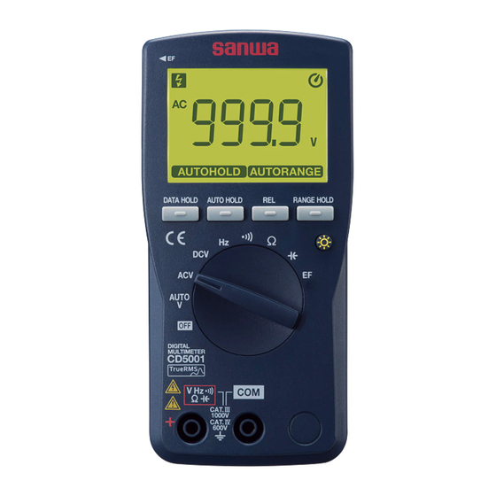
【3】 NAMES OF COMPONENT UNITS 3-1 Main Unit and Test Leads Hanger magnet (optional) Display mounting position EF antenna position REL button AUTO HOLD RANGE button HOLD DATA HOLD button button Test lead holders Rotary switch Backlight button Input terminal Input terminal Battery lid and stand (hereinafter referred to as battery lid) Removable test pin covers... -
Page 7: Display
3-2 Display ⑦ ⑧ ⑨ ⑥ ⑤ ④ ③ ① ⑬ ② ⑩ ⑪ ⑫ ① Numeral display part ② Relative mode ③ Polarity (-) ④ AC measurement function ⑤ DC measurement function ⑥ Voltage warning indicator ⑦ Continuity check ⑧... -
Page 8: Description Of Functions
【4】 DESCRIPTION OF FUNCTIONS 4-1 Rotary Switch Use this switch to turn the power on and off and to select various functions. 4-2 Data Hold Function: DATA HOLD Button When the DATA HOLD button is pressed, lights up on the display, and the current display value is held (retained). The display will not change even if the measurement input uctuates. -
Page 9: Relative Measurement Function
・ Auto Hold Operation Example Held Held (Ex.)6.000 V (Ex.) 5.900 V Changed before Held detection of (Ex.) 4.000 V (Ex.) 4.050 V stability Stable range Amount of Values below change within AUTO HOLD 200 counts stable range button pressed (or 1000 counts) not held Not held... -
Page 10: Auto Power Off Function
4-7 Auto Power OFF Function This instrument incorporates the Auto Power OFF function that turns off the display automatically about 30 minutes after the last operation, con- serving battery power. To reactivate the instrument, press the DATA HOLD or RANGE HOLD button, or turn the rotary switch to the OFF position and then turn it back again. -
Page 11: Ac Detection Method
To reactivate the buzzer, turn the rotary switch to the OFF position and then turn it back to any desired position. Note: ・The buzzer cannot be deactivated simultaneously with the deacti- vation of the Auto Power OFF function (see section 4-7). 4-11 AC Detection Method This instrument uses the true RMS (root mean square) method, representing the magnitude of AC as the same work amount as... -
Page 12: Measurement Procedure
【5】 MEASUREMENT PROCEDURE WARNING 1. Do not apply an input signal exceeding the maximum rated input of each function. 2. During measurement, do not turn the rotary switch. 3. During measurement, do not touch the test pin side of the ange of the test lead. - Page 13 START There is a risk of electric shock. Stop using the instrument and have it repaired. Are exteriors of Is the low battery the main unit and test leads Replace the batteries and indicator lit? damaged? restart the inspection from the beginning.
-
Page 14: Automatic Voltage Detection Measurement (Auto V)
5-2 Automatic Voltage Detection Measurement (AUTO V) This function automatically detects whether the input voltage is alternating current (AC) or direct current (DC). Rotary switch position Max. rated input value Range AUTO V AC/DC 999.9 V 999.9 V DC measurement AC measurement example example... -
Page 15: Ac Voltage Measurement (Acv)
5-3 AC Voltage Measurement (ACV) Rotary switch position Max. rated input value Range AC 999.9 V 999.9 mV/9.999 V/99.99 V/999.9 V Note: ・The displayed value may uctuate when the test leads are open, but this is not a malfunction. ・Measurement of an inverter power supply circuit may cause a mal- function. -
Page 16: Dc Voltage Measurement
5-4 DC Voltage Measurement (DCV) Rotary switch position Max. rated input value Range DC 999.9 V 999.9 mV/9.999 V/99.99 V/999.9 V Note: ・The displayed value may uctuate when the test leads are open, but this is not a malfunction. – 43 –... -
Page 17: Frequency Measurement
5-5 Frequency Measurement (Hz) CAUTION Never use the instrument for measuring frequencies to ground as the earth leakage breaker may trip. Rotary switch position Max. rated input value Range 9.999 Hz/99.99 Hz/999.9 Hz/ 99.99 kHz 9.999 kHz/99.99 kHz (≦1000 Vrms) (Auto range only)... -
Page 18: Continuity Check ( )
5-6 Continuity Check ( ) WARNING Never apply an external voltage to the measurement terminals. Rotary switch position Max. rated input value Range 999.9 999.9 Note: ・Open circuit voltage: Approx. 0.6 V DC. ・Continuity buzzer sound range: Approx. 30 to 70 or less. -
Page 19: Resistance Measurement ( )
5-7 Resistance Measurement ( ) WARNING Never apply an external voltage to the measurement terminals. Rotary switch position Max. rated input value Range 999.9 /9.999 k /99.99 k /999.9 k / 99.99 M 9.999 M /99.99 M Resistor Note: ・The open voltage across the measurement terminals is about 1.0 V DC or less. -
Page 20: Capacitance Measurement ( )
5-8 Capacitance Measurement ( ) WARNING Never apply an external voltage to the measurement terminals. CAUTION Remove electric charge in the capacitor prior to measurement. Because this instrument applies a current to the capacitor to measure, it is not suitable for measurement of electrolytic capacitors having a large leak current as a large error will occur. -
Page 21: Voltage Detection (Ef: Electric Field Detection)
5-9 Voltage Detection (EF: Electric Field Detection) WARNING Before performing voltage detection, con rm the operation of this instrument with a known power source. Be aware that the presence of voltage below the detection voltage does not necessarily mean there is no voltage. Do not use the instrument with the test leads xed in the test lead holder. -
Page 22: Maintenance And Inspection
If any of the above problems exists, stop using the instrument and request for repair. 6-2 Calibration For more information, please contact Sanwa’s authorized agent / distribution service provider, listed on our website. (See section 7-3.) 6-3 Cleaning and Storage... -
Page 23: Battery Replacement
6-4 Battery Replacement WARNING To avoid electric shock, do not remove the battery lid while an input is applied to the measured terminal or during measurement. Make sure that the rotary switch is set to OFF before replacing the batteries. ①... -
Page 24: After-Sale Service
Please contact a Sanwa authorized agent / distributor / service pro- vider, listed in our website, in your country with above information. An instrument sent to a Sanwa / agent / distributor without above information will be returned to the customer. -
Page 25: Sanwa Website
3) Repair after the warranty period has expired: In some cases, repair and transportation cost may become higher than the price of the product. Please contact a Sanwa authorized agent / service provider in advance. The minimum retention period of service functional parts is six (6) years after the discontinuation of manufacture. -
Page 26: Specifications
【8】 SPECIFICATIONS 8-1 General Specifications method ⊿‑Σ Operation method AC detection method True RMS (AC coupling) Display Max. 9999 counts Sampling rate Approx. 5 times/sec. (DCV) Over-range display “OL” shown in numeric section Range selection Auto and Manual Polarity switching Automatic selection (Only “-”... -
Page 27: Optional Accessories
Dimensions / mass 149 (H) x 72 (W) x 37 (D) mm, approx. 232 g (excluding protrusions, including batteries) Safety standards IEC61010-1, IEC61010-2-030, IEC61010-2-033 CAT. IV 600 V, CAT. III 1000 V IEC61010-031 EMC Directive IEC61326 Accessories Instruction manual, test leads (ATL101), LR03 / AAA alkaline battery x 2 8-2 Optional Accessories Hanger magnet: HM-1... - Page 28 ACV : AC Voltage Input Range Accuracy Remarks Resistance ・Accuracy guarantee 999.9 mV Approx. frequency range: 11 M 9.999 V 40 to 400 Hz (sine wave) 99.99 V Measurement not possible ±(1.0 %rdg + 5dgt) when frequency exceeds 1 kHz. ・Accuracy guarantee range Approx.
- Page 29 : Resistance Range Accuracy Remarks 999.9 9.999 k ±(0.5 %rdg + 5dgt) 99.99 k Open circuit voltage: Approx. ≤1.0 V 999.9 k ±(1.5 %rdg + 5dgt) 9.999 M ±(5.0 %rdg + 5dgt) 99.99 M : Capacitance Range Accuracy Remarks 999.9 nF ・Auto range only...
- Page 30 Accuracy calculation method Example: AC voltage measurement (AC) Indicated value: 200.0 V Range accuracy: 999.9 V range ... ±(1.0 %rdg+5dgt) Error: ± (200.0 V x 1.0 % + 5dgt) = ±2.5 V True value: 200.0 V ± 2.5 V (in a range of 197.5 V and 202.5 V) * In the 999.9 V range, 5 dgt corresponds to 0.5 V.
- Page 31 MEMO – 58 –...
- Page 32 本社=東京都千代田区外神田 2−4 −4 ・ 電波ビル 郵便番号=101-0021 ・ 電話=東京 (03) 3253−4871 (代) 大阪営業所=大阪市浪速区恵美須西2−7−2 郵便番号=556-0003 ・電話 = 大阪 (06) 6631−7361 (代) Dempa Bldg, 4-4 Sotokanda 2-Chome Chiyoda-Ku, Tokyo, Japan 01-2402 2040 6027...
Need help?
Do you have a question about the CD5001 and is the answer not in the manual?
Questions and answers