Table of Contents
Advertisement
Quick Links
Advertisement
Table of Contents

Subscribe to Our Youtube Channel
Related Manuals for Sanwa CD731A


Summary of Contents for Sanwa CD731A
- Page 1 CD731a DIGITAL MULTIMETER 取扱説明書 INSTRUCTION MANUAL...
-
Page 3: Table Of Contents
目 次 【1】 安全に関する項目∼ご使用の前に必ずお読みください。∼ 1−1 警告マークなどの記号説明 ………………………………………001 1−2 安全使用のための警告文 …………………………………………001 1−3 最大過負荷保護入力値 ……………………………………………002 【2】用途と特長 2−1 用 途 ………………………………………………………………003 2−2 特 長 ………………………………………………………………003 【3】各部の名称 3−1 本体・テストリード ………………………………………………004 3−2 表示器 ………………………………………………………………005 【4】機能説明 4−1 各種スイッチおよび機能 …………………………………………006 4−2 スタンドの使用方法 ………………………………………………007 【5】測定方法 5−1 始業点検 ……………………………………………………………008 5−2 電圧... - Page 4 Maintenance and inspection ………………………………042 Calibration ……………………………………………………042 ………………………043 How to Replace Battery and Fuse Cleaning and Storage ………………………………………044 【7】SPECIFICATIONS Measurement Range and Accuracy ………………………045 General Specifications………………………………………046 Optional accessories General Specifications ……………047 【8】After-Sales Service Warranty and Provision ……………………………………047 Repair …………………………………………………………048 SANWA web site ……………………………………………048...
-
Page 5: 1】 安全に関する項目~ご使用の前に必ずお読みください
【1】 安全に関する項目∼ご使用の前に必ずお読みください。∼ このたびはディジタルマルチメータCD731a型をお買い上げいた だき、誠にありがとうございます。 ご使用前にはこの取扱説明書をよくお読みいただき、正しく安全 にご使用ください。そして常にご覧いただけるように製品と一緒に して大切に保管してください。 本書で指定していない方法で使用すると、本製品の保護機能が損 なわれることがあります。 ・・・ ・・ 本文中の“ 警告”および“ 注意”の記載事項は、やけどや感電 などの事故防止のため、必ずお守りください。 1-1 警告マークなどの記号説明 本器および『取扱説明書』に使用されている記号と意味について :安全に使用するための特に重要な事項を示します。 ・警告文はやけどや感電などの人身事故を防止するためのものです。 ・注意文は本器を壊すおそれのあるお取り扱いについての注意 文です。 :高電圧が印加されることがあり危険ですので触らないでください。 :直流 (DC) ∼:交流 (AC) Ω:抵抗 :ブザー : ダイオード +:プラス −:マイナス : 二重絶縁または強化絶縁 :ヒューズ : グランド 1-2 安全使用のための警告文... - Page 6 16. リヤケースをはずした状態では使用しないこと。 17. 測定中はテストリードのつばよりテストピン側を持たないこと。 18. 測定中は他のファンクションに切り換えたりしないこと。 19. 測定ごとにレンジ、ファンクション、測定端子の確認を確 実に行うこと。 10. 本器または手が水などでぬれた状態で使用しないこと。 11. 内蔵電池および内蔵ヒューズ交換を除く修理・改造は行わな いこと。 12. 年 1 回以上の点検は必ず行うこと。 13. 屋内で使用すること。 注 意 1. トランスや大電流路など強磁界の発生している近く、無線機 など強電界の発生している近くでは正常な測定が出来ない場 合があります。 2. インバータ回路のような特殊な波形では、本器が誤動作や正 常な測定が出来ない場合があります。 1-3 最大過負荷保護入力値 ファンクション 入力端子 最大測定入力値 最大過負荷保護入力値 DC 1000 V DC 1000 V、AC 750 V またはpeak max.
-
Page 7: 2】用途と特長
【2】用途と特長 2-1 用 途 本器は小容量電路の測定用に設計された、携帯用ディジタルマル チメータです。小型通信機器や家電製品、電灯線電圧や各種電池の 測定などはもちろん、付加機能を使って回路分析などにも威力を発 揮します。 2-2 特 長 ・4000 カウント表示 ・データホールド・レンジホールド機能付き ・約30 分で作動するオートパワーセーブ付き ・静電容量測定ファンクション付き ・テストリード固定、壁掛け可能なホルスタ付き ・4・20 A測定端子には誤挿入防止のセーフティカバー付き ・本体ケースおよび回路基板には難燃材を使用 ・IEC 61010-1に準拠 (25 ページ “安全規格” の項参照) 注 意:出荷時の電池について 工場出荷時にモニター用電池が組み込まれておりますので、記載された電池 寿命に満たないうちに切れることがあります。 モニター用電池とは製品の機能や性能をチェックするための電池のことです。 取扱説明書に掲載した仕様、外観など、改良その他やむを得な い理由により、予告なしに変更することがありますがご了承く ださい。 − 3 −... -
Page 8: 3】各部の名称
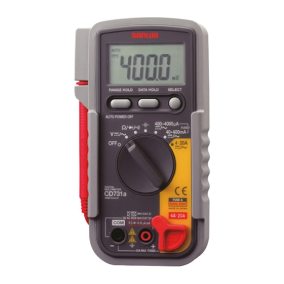
【3】各部の名称 3-1 本体・テストリード ホルスタ (H-70) テストリード 固定部 液晶表示器 壁掛け レンジホールド データホールド スイッチ スイッチ セレクト 電源スイッチ兼 スイッチ ファンクション スタンド スイッチ セーフティ カバー 4・20 A測定端子 COM (−) 端子 V, Ω, ●, ●, ●, μA,mA (+) 測定端子 1000 V 1000 V 750 V) 600 V 〔Fig 1〕... - Page 9 3-2 表示器 − 5 −...
-
Page 10: 4】機能説明
【4】機能説明 4-1 各種スイッチおよび機能 ○電源スイッチ兼ファンクションスイッチ このスイッチを回して電源のON/OFFおよび各ファンクションに 切り換えます。 このとき、表示器の右方にはファンクションに対応した単位が表 示されます。 ○レンジホールドスイッチ (RANGE HOLD) 電圧、電流、抵抗ファンクションにて、特定のレンジに固定した い場合に使用します。このスイッチを押すと、表示器の“AUTO” の表示が消えレンジが固定され、マニュアルモードになります。 このスイッチを押すたびにレンジが移動しますので、表示器の単 位と小数点の位置を確認しながら適正なレンジを選択してくださ い。オートモードに復帰させる場合には、 “AUTO”表示が出る までこのスイッチを押し続けます。 ○データホールドスイッチ (DATA HOLD) 表示器に表示されている測定データを固定させる時使用します。 このスイッチを押すと表示器に“DH”が点灯し、その時点の データ表示が固定され、入力信号が変化しても表示は変化しませ ん。再びこのスイッチを押すと表示器の“DH”は消え、ホール ド状態は解除され、測定状態に戻ります。 ○セレクトスイッチ (SELECT) このスイッチを押す (→) ごとに、各ファンクションのモードが下 記のように切り換わります。 V●/∼ ● → ∼ → ● → ∼... - Page 11 ○オートパワーオフ(セーブ) 本器は約 30 分で自動的に表示が消え、 電池の消費を抑えるオート パワーオフ(セーブ)機能付きです。ただしオートパワーセーブ は表示が消えた状態でも多少電池は消費しますので長時間ご使用 にならない場合はOFFに合わせておいてください。また、オート パワーオフ(セーブ)作動直前にそのままご使用になりたい場合 は、データホールドスイッチを押してください。 この機能を解除するには、SELECTボタンを押したままファンク ションスイッチを回し、電源をONにしてください。 ○オーバー表示(O.L) 本器に最大定格を超える入力が加わった場合には表示器に“O.L” 表示が出ます。電圧、電流ファンクション等で、O.L表示がされ た場合はすみやかに入力を止めてください。 4-2 スタンドの使用方法 本体を立ててご使用になりたい場合は、本体裏のスタンドを図の ように立ててご使用ください。 〔Fig 3〕 − 7 −...
-
Page 12: 5】測定方法
【5】測定方法 5-1 始業点検 警 告 1. 本体およびテストリードが傷んでいたり、壊れている場合は 使用しないこと。 2. テストリードが切れたりしていないことを確認すること。 感電の恐れがありま 点検スタート す。使用をやめ修理 ▼ してください はい 本体とテスト はい 電池消耗表示 電池を交換し、もう リードの外観は破損して は点灯していますか? 一度点検をやり直し いますか? * てください いいえ いいえ ▼ ▼ 黒プラグをCOM 赤、黒のテスト テストリードを交換 ① −端子に差し込 ピンをショート ⑤ しても良くならない みます します 場合は、修理が必要... -
Page 13: 電圧 (V) 測定
5-2 電圧 (V) 測定 最大測定電圧 直流電圧 DC 1000 V、交流電圧 AC 750 V 警 告 1. 最大測定入力電圧を超えた入力信号を加えないこと。 2. 測定中はファンクションスイッチを切り換えないこと。 3. 測定中はテストリードのつばよりテストピン側を持たないこと。 1)測定対象 DCV:電池や直流回路の電圧を測ります。 ACV :電灯線電圧などの正弦波交流電圧を測ります。 2)測定レンジ DCV:400 mV∼1000 V (5 レンジ) , ACV:4 V∼750 V (4 レンジ) 3)測定方法 ①テストリードの赤プラグを+測定端子に、黒プラグをCOM −端子に差し込みます。 ②ファンクションスイッチをV● /∼に合わせます。... - Page 14 5-3 抵抗 (Ω) 測定 最大測定抵抗 40 MΩ 警 告 入力端子には外部よりの電圧を絶対に加えないこと。 1)測定対象 抵抗器や回路の抵抗を測ります。 2)測定レンジ 400 Ω∼40 Mまでの6 レンジ 3)測定方法 ①テストリードの赤プラグを+測定端子に、黒プラグをCOM −端子に差し込みます。 ②ファンクションスイッチをΩ/ ●/●に合わせます。 ③セレクトスイッチでMΩ (kΩ) を表示させます。 ④被測定物に赤、 黒のテストピンをそれぞれあてて測定します。 ⑤表示器の表示値を読み取ります。 ⑥測定後は被測定回路から赤黒のテストピンをはずします。 ⑦ファンクションスイッチをOFFに戻します。 ●測定端子間の開放電圧は約0.4 Vです。 ●測定に際しノイズの影響を受ける場合は、被測定物をCOM (−) の電位でシールドしてください。 ●テストピンや被測定物に指を触れて測定すると、人体の抵抗 の影響を受け、測定誤差を生じます。 ⑥ ⑥ ④ 抵抗器...
-
Page 15: ダイオード ( ) テスト
5-4 ダイオード ( ) テスト 警 告 測定端子には外部よりの電圧を絶対に加えないこと。 1)使用対象 ダイオードの良否をテストします。 2)使用方法 ①テストリードの赤プラグを +測定端子に、黒プラグを− COM入力端子に差し込みます。 ②ファンクションスイッチをΩ/● /●に合わせます。 ③セレクトスイッチで を選択します。 ( 表示器の上方に表示される) ④ダイオードのカソード側に黒のテストピンを、アノード側 に赤のテストピンを接続します。 ⑤表示器にダイオードの順方向電圧降下が表示されます。特殊品 を除き、 ダイオードの種類により、 0.2∼0.7 Vのほぼ一定値です。 ⑥ダイオードのアノード、カソードを入れ換えて接続します。 この時の表示値がテストピンをはずしたときと同じ値であれば合格です。 ※⑤・⑥の確認ができれば、ダイオードは正常です。 ⑦測定後は被測定物から赤黒のテストピンをはずします。 ⑧ファンクションスイッチをOFFに戻します。 ●入力端子間の開放電圧は約1.1∼1.5 Vです。 ●ダイオードの順方向電圧が、開放電圧以上の場合は、順方向 テストのときでも「OL」表示となります。 アノード カソード Anode Cathode ⑤・⑦... -
Page 16: 導通 ( ) チェック
5-5 導通 ( ) チェック 警 告 測定端子には外部よりの電圧を絶対に加えないこと。 1)使用対象 配線の導通確認や選定に用います。 2)使用方法 ①テストリードの赤プラグを+測定端子に、黒プラグをCOM −端子に差し込みます。 ②ファンクションスイッチをΩ/ ●/●に合わせます。 ③セレクトスイッチで●を選択します。 ( 表示器上方に表示さ れます) ④被測定回路や導体の2点間に赤黒のテストピンをあてチェッ クします。 ⑤ブザーが鳴るか鳴らないかで導通を確認します。 ・被測定抵抗が約10∼120 Ω以下では発音と抵抗値を表示し ます。 ・上記以上では抵抗値表示のみとなります。 ⑥測定後は被測定物から赤、黒のテストピンをはずします。 ⑦ファンクションスイッチをOFFに戻します。 ●入力端子間の開放電圧は約0.4 Vです。 ●発音直後、一瞬音が途切れますが、故障ではありません。 ●抵抗値の大きさによっては発音にノイズが重畳しますが、故障 ではありません。 延長コード Extension cord ⑥ ⑥ ⑤ ④ ②... -
Page 17: 静電容量 ( ) 測定
5-6 静電容量 ( ) 測定 警 告 測定端子には外部よりの電圧を絶対に加えないこと。 1)測定対象 コンデンサの静電容量を測ります。 2)測定レンジ 40 nF∼100 μFまでの 5 レンジ (参考、1000 nF=1 μF) 3)測定方法 ①テストリードの赤プラグを+測定端子に、テストリードの 黒プラグをCOM−端子に差し込みます。 ②ファンクションスイッチを● に合わせます。 ③セレクトスイッチを押して、 表示器の表示を00.00 nFにしま す (表示器上方にRELが表示される) 。 ④コンデンサに赤黒のテストピンをそれぞれあてます。 ⑤表示器の表示値を読みとります。 ⑥測定後は被測定物から赤黒のテストピンをはなします。 ⑦ファンクションスイッチをOFFに戻します。 ●コンデンサに充電された電荷は測定前に必ず、放電してくだ さい。 ●静電容量測定ファンクションは、オートレンジのみでマニュ アルレンジには設定できません。 ●100 nF以下の測定では測定端子開放時に大きく数字が残りま すが故障ではありません。セレクトスイッチで00.00 nFにしま... -
Page 18: 電流 (A) 測定
5-7 電流 (A) 測定 警 告 〈5-7-1項、5-7-2項が対象となります〉 1. 必ず負荷を通して本器が直列に接続されるようにすること。 電 源 電 源 負 荷 負 荷 × ○ 誤った危険な 正しい測定 測定 〔Fig 11〕 2. 測定端子には電圧を絶対に加えないこと。 3. 最大測定電流を超える入力は加えないこと。 5-7-1 直流・交流電流 (DC/AC μA・mA) 最大測定電流 DC/AC 4000 μA・400 mA 1)測定対象 直流電流:電池や直流回路の電流を測ります。 交流電流:交流回路の電流を測ります。 2)測定レンジ... - Page 19 ③セレクトスイッチで ● (DC) または∼ (AC) を選択します。 ④被測定回路を切り離し負荷と直列になるように接続します。 ⑤表示器の表示を読み取ります。 ⑥測定終了後は被測定回路から赤黒のテストピンをはずします。 ⑦ファンクションスイッチをOFFに戻します。 ●入力信号を加えても表示がほとんど変化しない場合や、予想した 電流値より著しく小さい値の場合は、測定端子やファンクション スイッチの位置が違っていたり、ヒューズ (φ5×20 mmサイズ 500 mA/250 V) が遮断している可能性があります。確認してください。 ●本器の交流検波方式は平均値方式のため、正弦波以外の波形 では測定誤差を生じます。なお周波数範囲は40∼500 Hzです。 ③ 抵抗器 電池 ⑤ Resistor Battery ⑥ ⑥ ② ④ ⑦ ① DC 40・400 mAレンジの使用例 Measuring DC 40・400 mA 〔Fig 12〕...
- Page 20 1)測定対象 20 A以下の回路電流の測定に使用します。 2)測定レンジ DCA、ACA各 2 レンジ (4・20 A) 3)測定方法 ①セーフティーカバーを左にスライドさせ、テストリードの 赤プラグを4・20 A測定端子に、黒プラグをCOM−端子に差 し込みます。 ②ファンクションスイッチを4・20 A ●/∼に合わせます。 ③セレクトスイッチで ● (DC) または∼ (AC) を選択します。 ④被測定回路を切り離し負荷と直列になるように接続します。 ⑤表示器の表示を読み取ります。 ⑥測定終了後は被測定回路から赤黒のテストピンをはずします。 ⑦ファンクションスイッチをOFFに戻します。 ●入力信号を加えても表示がほとんど変化しない場合や、予想 した電流値より著しく小さい値の場合は、測定端子やファン クションスイッチの位置が違っていたり、ヒューズ (φ6.3× 32 mmサイズ20 A/250 V) が遮断している可能性がありますの で、確認をしてください。 ●本器の交流検波方式は平均値方式のため、正弦波以外の波形 の測定では測定誤差を生じます。 周波数範囲は40∼500 Hzです。 ●連続測定可能範囲:5 A 以下...
-
Page 21: 別売付属品による測定
5-8-1 交流電流プローブ (CL-20D) による測定 最大測定電流 AC 200 A 1)測定対象 家電機器の消費電流や電源設備など、 50∼60 Hzの正弦波交流 の測定に用います。 2)測定レンジ 20 A、200 Aの 2 レンジ 3)測定方法 ①電流プローブの赤プラグを+測定端子に、黒プラグをCOM −端子に差し込みます。 ②本器 (CD731a) のファンクションスイッチをV●/∼に合わせ ます。 ③セレクトスイッチで∼ (AC) 選択し、レンジホールドスイッ チで4 Vレンジに設定します。 ④電流プローブのレンジ設定つまみを20 Aまたは200 Aレンジ に合わせます。 ⑤電流プローブの鉄心を開き、被測定導体をクランプします。 ⑥電流プローブのレンジが20 Aの場合は表示値を10 倍、200 A レンジの場合は100 倍し、 A (アンペア) 単位で読み取ります。... -
Page 22: 直流・交流電流プローブ (Cl-22Ad) による測定
ます。 DC 20 A → 0.1 倍 AC 20 A → 100 倍 DC 200 A → 1 倍 AC 200 A → 1000 倍 ⑧測定後は電流プローブの鉄心を開き、被測定導体から電流 プローブをはずします。 ⑨本器 (CD731a) とプローブ (CL-22AD) のスイッチをOFFに戻 します。 ⑦ ③ ⑥⑧ ④ ② ⑤ ⑨... -
Page 23: 直流電流プローブ (Cl33Dc) による測定
イッチで400 mVレンジに設定します。 ④電流プローブのレンジ設定つまみを30 Aまたは300 Aレンジ に合わせ、ゼロ調整つまみを回し 、本器 (CD731a) の表示 を000.0 mVにします。 ⑤電流プローブの鉄心を開き、被測定導体をクランプします。 ⑥電流プローブのレンジが30 Aの場合は表示値を0.1 倍、 300 A レンジの場合は 1 倍して表示器の表示をA (アンペア) 単位 で読み取ります。 ⑦測定後は電流プローブの鉄心を開き、被測定導体から電流 プローブをはずします。 ⑧本器 (CD731a) とプローブ (CL33DC) のスイッチをOFFに戻 します。 ⑥ ③ ⑤⑦ ② ⑧ ⑧ ④ ① 〔Fig 16〕... -
Page 24: 直流高電圧プローブ (Hv-60) による測定
5-8-4 直流高電圧プローブ(HV-60)による測定 最大測定電圧 DC 30 kV 警 告 1.このプローブは微小電流回路測定用です。送電線などの強電 用には使用しないこと。 2.プローブの最大測定電圧 (DC 30 kV) を超える電圧は印加しないこと。 3.測定中は他のファンクションに切り換えないこと。 4.測定中はプローブのつばより測定ピン側を持たないこと。 1)測定対象:テレビのブラウン管などのアノード電圧、フォー カス用高電圧など高インピーダンス回路の電圧測定 2)測定レンジ:DC 1000 Vレンジを使用 3)測定方法 ①高圧プローブの赤プラグをV入力端子に、黒プラグをCOM 入力端子に差し込みます。 ②ファンクションスイッチをDCVに合わせ、レンジホールド スイッチでDC 1000 Vレンジにします。 ③被測定物のアースラインに黒のクリップを接続し、被測定 箇所にプローブ先端のピンをあてます。 ④表示器の表示値を0.1 倍してkV単位で読み取ります。 ⑤測定後は被測定回路からピンを離してから、クリップをは ずします。 ●HV-60は交流電圧の測定には使用できません。 ブラウン管 アノード Anode ⑤ ④... -
Page 25: 内蔵電池・内蔵ヒューズの交換
【6】保守管理ついて 警 告 1. この項目は安全上重要です。本説明書をよく理解して管理を 行ってください。 2. 安全と確度の維持のために 1 年に1 回以上は校正、点検を実 施してください。 6-1 保守点検 1)外観 落下などにより、外観が壊れていないか? 2)テストリード ・入力端子にプラグを差し込んだときに緩みはないか? ・テストリードの傷んだり、どこかの箇所から芯線が露出し ていないか? ●テストリードが切れていないことを、P.8【5】5-1を参照し て確認してください。 6-2 校 正 校正、点検については三和電気計器 (株) サービス課までお問い 合わせください。 (P.24[送り先]参照) 6-3 内蔵電池・内蔵ヒューズの交換 警 告 1. 測定端子に入力が加わった状態でリヤケースをはずすと感電 のおそれがありますので必ず入力が加わってないことを確認 して作業を行うこと。 2. 交換用ヒューズは同定格のものを使用すること。ヒューズの 代用品を用いたり、短絡することは絶対にしないこと。... - Page 26 〈内蔵電池の交換方法〉 ①ホルスタを本体より取りはずします。 ②本体裏側のスタンドを開き、止めねじをプラスねじ回しではず します。 ③本体下側から開くようにリヤケースをはずし、リヤケース内側 の消耗した電池をはずします。 ④●、●の極性を間違えぬよう注意し、新品の電池と交換します。 ⑤リヤケースを取り付け、ねじ止めし、スタンド・ホルスタを元 に戻します。 〈内蔵ヒューズの交換方法〉 使用ヒューズ定格 500 mA/250 V (φ5×20 mm しゃ断容量1500 A、 セラミック管ヒューズ) 20 A/250 V .(φ6.3×32 mm しゃ断容量200 kA、セラミック管ヒューズ) ①ホルスタを本体より取りはずします。 ②本体裏側のスタンドを開き、止めねじをプラスねじ回しではず します。 ③本体下側から開くようにリヤケースをはずし、溶断したヒュー ズを取り出します。 ④新品のヒューズと交換します。 ⑤リヤケースを取り付け、ねじ止めし、スタンド・ホルスタを元 に戻します。 単三乾電池 (R6) ※リヤケース内側にあります。 Battery (R6, 1.5 V×2) ※...
-
Page 27: 7】アフターサービスについて
6-4 清掃と保管について 注 意 1. パネル、リヤケース、ダイヤルは揮発性溶剤(シンナーやア ルコールなど)で変質することがあります。汚れは柔らかい 布に少量の水を含ませてふき取ってください。 2. 振動の多い場所や落下のおそれがある場所には保管しないでください。 3. 直射日光下、高温、低温、多湿、結露のある場所での保管は 避けてください。 4. 長期間使用しない場合、 内蔵電池を必ず抜いておいてください。 以上の注意項目を守り、環境の良い場所 (P.25【8】参照) に保管 してください。 【7】アフターサービスについて 7-1 保証期間について 本製品の保証期間は、お買い上げの日より 3 年間です。 ただし、日本国内で購入し日本国内でご使用いただく場合に限ります。 また、製品本体の確度は1年保証、製品付属の電池、ヒューズ、テストリ ード等は保証対象外とさせていただきます。 7-2 修理について 1)修理依頼の前に次の項目をご確認ください。 ・内蔵電池の容量はありますか?装着の極性は正しいですか? ・テストリードは断線していませんか? ・内蔵ヒューズは切れていませんか? 2)保証期間中の修理 ・保証書の記載内容によって修理させていただきます。 3)保証期間経過後の修理 ・修理費用や輸送費用が製品価格より高くなる場合もありま すので、事前にお問い合わせください。 ・本品の補修用性能部品の最低保有期間は、製造打切後... - Page 28 20 A/250 V ¥1100 (税込¥1155)¥120 ( 10 本迄) 商品番号 F1204 セラミック管ヒューズ/しゃ断容量200 kA 7-3 お問い合わせ先 三和電気計器 (株) 東京本社 :TEL (03) 3253―4871 FAX (03) 3251―7022 大阪営業所 :TEL (06) 6631―7361 FAX (06) 6644―3249 三和電気計器 (株) ホームページ:http://www.sanwa-meter.co.jp お客様計測相談室: 0120―51―3930 受付時間 9 : 30∼12: 00 13:00∼17 :00(土日祭日を除く) − 24 −...
-
Page 29: 8】仕 様
【8】仕 様 8-1 一般仕様 動 作 方 式:△Σ方式 表 示:4000 カウント レンジ切り換え:オートおよびマニュアル オ ー バ ー 表 示:O.Lマーク点灯 (20 A、 DC 1000 V、 AC 750 Vレンジを除く) 極 性:自動切り換え (−のみ表示) 電 池 消 耗 表 示:内部電池の消耗時、表示器に マークが点灯 −+ サンプリングレート:3 回/秒 交 流 検 波 方 式:平均値方式 (平均値を実効値に換算) 確度保証温湿度範囲... - Page 30 8-3 測定範囲および確度 確度保証条件:23 ℃±5 ℃ 80 %RH 結露のないこと レ ン ジ 内 部 抵 抗 確 度 備 考 フ ァ ン ク シ ョ ン 400.0 mV ≧100 MΩ ± (0.5 %rdg+2 dgt) 4.000 V 約11 MΩ 直流電圧 40.00 V ±...
-
Page 31: Safety Precautions:before Use, Read The Following Safety Precautions
【1】 SAFETY PRECAUTIONS : Before use, read the following safety precautions This instruction manual explains how to use your multimeter CD731a safely. Before use, please read this manual thoroughly. After reading it, keep it together with the product for reference to it when necessary. -
Page 32: Maximum Overload Protection Input
05. Never use meter if the meter or test leads are damaged or broken. 06. Never use uncased meter. 07. Be sure to use a fuse of the specified rating or type. Never use a substitute of the fuse or never make a short circuit of the fuse. 08. -
Page 33: Application And Features
【2】APPLICATION AND FEATURES 2-1 Application This instrument is portable multimeter designated for measurement of weak current circuit. 2-2 Features ・4000 counts disply. ・Auto power save 30 min. ・With the capacity measurement function. ・The current function is the semi auto ranges. ・Main unit case and the circuit board is made of fire retarding materials. -
Page 34: Multimeter, Test Leads
3-2 Multimeter, Test leads Holster Test lead Display Data hold Range hold switch switch Select Power switch switch and function Stand switch Safety cover 4・20 A input terminal COM − input terminal Ω,● , ●, ●,μA, mA + input terminal Removable test pin covers When not covered:CAT. -
Page 35: Description Of Functions
【4】Description of Functions 4-1 Switch and description ○Power switch and function switch Turn this switch to turn on and off the power and to select the , μA, mA, A. functions of V, /● /●,● ○Range hold switch Pressing this switch once sets the manual mode and the range is fixed. -
Page 36: How To Use The Stand
○Auto power off, Auto powersave This device incorporates auto-power-off function that turns off the display in about 30 minutes to save battery draining. There is a little battery draining even if the auto power save function is activated, therefore be sure to return the Power/Function knob to OFF after measurement. -
Page 37: Measurement Procedure
【5】MEASUREMENT PROCEDURE 5-1 Start-up Inspection WARNING 1. Never use meter if the meter or test leads are damaged or broken. 2. Make sure that the test leads are not cut or otherwise damaged. ④ ③ ① ② 〔Fig 4〕 − 33 −... -
Page 38: Voltage Measurement
●In the AC4 V range, a figure of about 3~9 counts will stay on even if no input signal is present. But it is not malfunction. ●In the manual mode of the ACV function, the CD731a can be set to the 400 mV range and shows an approximate value. But its accuracy is not guaranteed. -
Page 39: Resistance Measurement ( )
5-3 Resistance Measurement ( ) WARNING Never apply voltage to the input terminals. 1) Application Resistance of resistors and circuits are measured. 2) Measuring ranges ∼40 M (6 ranges) 3) Measurement procedure (See Fig 7, page 10) ①Connect the black plug of the test lead to the COM − input terminal and the red plug to the +... -
Page 40: Checking Continuity
③Select the select switch at " ". ④Apply the black test pin to the cathode of the diode and the red test pin to the anode. ⑤Make sure that the display shows a diode forward voltage drop. ⑥Replace the red and black test pins, make sure that the display is the same as that when the test leads are released. -
Page 41: Capacity Measurement
It is therefore recommended that an object to measure (capacitor) be directly connected between the (+) and (−) measuring terminals of the CD731a. ●As the capacitance increases, the measuring time becomes longer. Example: 2 to 4 seconds at 10 μF 5 to 8 seconds at 50 μF... -
Page 42: Current Measurement (Μa, Ma, A)
5-7 Current Measurement (μA, mA, A) WARNING 1. Never apply voltage to the input terminals. 2. Be sure to make a series connection via load. (please see to above drawing) 3. Do not apply an input exceeding the maximum rated current to the input terminals. -
Page 43: Current Measurement (A)
DCA: 4・20 A (2 ranges), ACA: 4・20 A (2 ranges) 3) Measurement procedure (See Fig 13, page 16) ①Slide the safety cover of the CD731a to the left and insert the red plug of the test leads to the 4・20 A measuring terminal and the black plug to the COM (−) terminal. -
Page 44: How To Use Optional Products
⑤Select either 20 A or 200 A with selector knob of clamp probe. probe to make the display of the CD731a show "000.0". ⑥Open the clamp part, have electric wire (one line) clamped. − 40 −... -
Page 45: Dc Clamp Probe (Cl33Dc)
⑦Read the value on the display as follows. DC 20 A : multiplying by 0.1 AC 20 A : multiplying by 100 DC 200 A : multiplying by 1 AC 200 A : multiplying by 1000 ⑧After measurement, open the clamp part and release clamp probe from the electric wire. -
Page 46: Maintenance
1) Measurement item Anode voltage of cathode ray tube, high focusing voltage, and voltage of high-impedance circuit 2) Measurement range : DC1000 V range (Set manually in the manual mode) 3) Measuring method ①Insert the red plug of the high-voltage probe into the V input terminal and the black plug into the COM terminal. -
Page 47: How To Replace Battery And Fuse
6-3 How to Replace Battery and Fuse (See Fig 18, page 22) WARNING 1. If the rear case is removed with input applied to the input terminals, you may get electrical shock. Before starting the work, always make ure that no inputs is applied. 2. -
Page 48: Cleaning And Storage
6-4 Cleaning and Storage CAUTION 1. The panel and the case are not resistant to volatile solvent and must not be cleaned with thinner or alcohol. For cleaning, use dry, soft cloth and wipe it lightly. 2. The panel and the case are not resistant to heat. Do not place the instrument near heat-generating devices (such as a soldering iron). -
Page 49: Specifications
【7】SPECIFICATIONS 7-1 Measurement Range and Accuracy Accuracy assurance range : 23±5 ˚C 80 %RH MAX. No condensaition. Input Resistance Remarks Function ≧100 M ±(0.5 %rdg+2 dgt) 400.0 mV 4.000 V Approx. 11 M ±(0.9 %rdg+2 dgt) 40.00 V Approx. 10 M 400.0 V ±(1.0 %rdg+2 dgt) 1000 V... -
Page 50: General Specifications
7-2 General Specifications Measuring Method : △Σmethod Display : 4000 counts Range selection : Auto and manual ranges Over display : "O.L" is displayed (except DC/AC 20 A, DC 1000 V, AC 750 V ranges) Polarity : Automatic selection (only "−" is displayed) Battery discharge display : If the internal battery has been consumed and the voltage drops, the display shows. -
Page 51: After-Sales Service
・Corrent probe CL-20D, CL-22AD, CL33DC・Carrying case C-SP 【8】After-Sales Service 8-1 Warranty and Provision Sanwa offers comprehensive warranty services to its end-users and to its product resellers. Under Sanwa's general warranty policy, each instrument is warranted to be free from defects in workmanship or material under normal use for the period of one (1) year from the date of purchase. -
Page 52: Repair
3) Repair after the warranty period has expired: In some cases, repair and transportation cost may become higher than the price of the product. Please contact Sanwa authorized agent / service provider in advance. The minimum retention period of service functional parts is 6 years after the discontinuation of manufacture. -
Page 54: 保証書
保証書 ご氏名 CD731a 型 名 様 製造No. ご住所 この製品は厳密なる品質管理を経てお 届けするものです。 本保証書は所定項目をご記入の上保管 していただき、アフターサービスの際 ご提出ください。 ※本保証書は再発行はいたしませんの で大切に保管してください。 保証期間 本社 = 東京都千代田区外神田2−4−4 ・ 電波ビル ご購入日 年 月より 3 年間 郵便番号 = 101-0021・電話 = 東京 (03) 3253−4871 ( 代) 保証規定 保証期間中に正常な使用状態のもとで、万一故障が発生した場合には無償で修理いたし ます。ただし下記事項に該当する場合は無償修理の対象から除外いたします。 記 1. 取扱説明書と異なる不適当な取扱いまたは使用による故障... - Page 56 本社 = 東京都千代田区外神田2−4−4 ・ 電波ビル 郵便番号 = 101-0021・電話 = 東京 (03) 3253−4871 ( 代) 大阪営業所 = 大阪市浪速区恵美須西2−7−2 郵便番号 = 556-0003・電話 = 大阪 (06) 6631−7361 ( 代) SANWA ELECTRIC INSTRUMENT CO.,LTD. Dempa Bldg, 4-4 Sotokanda2-Chome Chiyoda-Ku,Tokyo,Japan 植物油インキを使用しています。 09-1212 2040 2040...
Need help?
Do you have a question about the CD731A and is the answer not in the manual?
Questions and answers