Table of Contents
Advertisement
Quick Links
Advertisement
Table of Contents

Subscribe to Our Youtube Channel
Related Manuals for Sanwa DMM PC520M


Summary of Contents for Sanwa DMM PC520M
- Page 1 PC520M DIGITAL MULTIMETER INSTRUCTION MANUAL...
-
Page 2: Table Of Contents
CONTENTS SAFETY PRECAUTIONS Explanation of Warning Symbols Warning Instruction for Safe Use Overload Protections APPLICATION AND FEATURES Applications Features NAME OF FUNCTION Multimeter and Test Leads Display DESCRIPTION OF FUNCTIONS Function Switch Auto Power Off Low Battery indication Measurement Function select Range Hold Data Hold Auto Lead Resistance Calibration... - Page 3 MAINTENANCE Maintenance and Inspection Calibration Battery and Fuse Replacement Storage AFTER-SALE SERVICE Warranty and Provision Repair SANWA web site SPECIFICATIONS General Specification Measurement Range and Accuracy...
-
Page 4: Safety Precautions
SAFETY PRECAUTIONS *Before use, read the following safety precautions. This instruction manual explains how to use your new digital multimeter PC520M safely. Before use, please read this manual thoroughly, and, keep it together with the product for your reference. The instruction given under the heading " WARNING"... -
Page 5: Overload Protections
16. Never use uncased meter. 17. Be sure to use a fuse of the specified rating or type. Never use a substitute of the fuse or never make a short circuit of the fuse. 18. When connecting and disconnecting the test leads, connect the ground lead (black one) first. -
Page 6: Application And Features
[2] APPLICATION AND FEATURES 2-1 Applications This instrument is portable digital multimeter designed for measurement of weak current circuits. It plays an important role in circuitry analysis by using additional functions as well as measurements of small type communication equipment, electrical home appliance, lighting voltage and batteries of various type. -
Page 7: Name Of Function
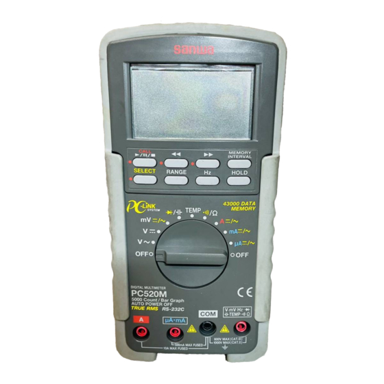
[3] NAME OF FUNCTIONS 3-1 Multimeter and Test Leads LCD Display BACKWARD Button FORWAD Button CALL START•PAUSE•STOP MEMORY Button INTERVAL Button DATA HOLD SELECT Button Button RANGE HOLD FREQUENCY Button SELECT Button Holster POWER Switch and FUNCTION Switch V•mV•Hz• • A measuring terminal •TEMP•... -
Page 8: Display
3-2 Display Display value in the main display area Auto range display : Data hold display : Capture mode display : DC measurement display : AC measurement display Minus polarity for numeral data Testing diode display Battery discharge warring display Analog bargraph MAX: Maximum value display MIN: Minimum value display... -
Page 9: Description Of Functions
[4] DESCRIPTION OF FUNCTIONS 4-1 Function Switch Turn this switch to turn on and off the power and to select the functions of "V /mV/ • /Temp/Ω• /A/mA/µA". 4-2 Auto Power Off The Auto Power Off mode turns the meter off automatically to extend battery life after approximately 17 minutes of no activities. -
Page 10: Range Hold
4-5 Range Hold Press the RANGE button momentarily to set the manual range mode then 'AUTO' disappears in the display. In manual range mode, press the button again to step through the ranges. To return to the auto mode, press the button for 1 sec. or more then AUTO is shown. -
Page 11: Set Beeper Off
4-8 Set Beeper Off Press the Hz button while turning the function switch on to disable the Beeper feature. 4-9 RS232C Interface The instrument equips with an optical isolated interface port at the back of meter body for data communication. Optional accessories KB-RS2 (RS232 cable), KB-USB2(USB cable) and PC Link or PC Link Plus (software), are required for Data logging system. - Page 12 Note: • Data logging mode is not available for 50.00µF, 500.0µF and 9999µF range because of slow response for large capacitance. • The sampling speed cannot be set when the data logging is running. Please set the sampling speed before starting the data logging, or pause the data if you want to alter the sampling speed setting during data logging.
- Page 13 4-10-3 Pause and Resume data logging mode Press the button momentarily to pause. The LCD annunciator 'H' will be flashing when paused. Press the button momentarily to resume data logging. 4-10-4 Data Review mode After exiting data logging or when in pause, you can review logged data, MAX and MIN and inflection points though out built- in memory.
- Page 14 4-10-6 Search MAX and MIN data throughout built-in memory Press CALL button to recall logged data. Press both of button at the same time to show maximum and minimum readings of the logged date alternatively. Press the CALL button momentarily again to exit Data review mode.
-
Page 15: Words
• When the logged data item number exceeded 9999 (where available), the bar-graph will also be used to indicate the most significant digit of the item number in the order of 10000. That is 1 = 10000, 2 = 20000, ... etc. •... - Page 16 Crest Factor The crest factor (CF) is expressed by a value obtained by dividing the peak value of the signal by its RMS value. Most common waveforms such as sine wave and triangular wave have a relatively low crest factor. The voltages and crest factors of typical waveforms are shown in the table.
-
Page 17: Measurement Procedure
[5] MEASUREMENT PROCEDURE 5-1 Start-Up Inspection WARNING 1. Never use meter if the meter or test leads are damaged or broken. 2. Make sure that the test leads are not cut or otherwise damaged. START Main unit Damaged and test leads damaged? No damaged Check continuty of test... -
Page 18: Voltage Measurement
5-2 Voltage Measurement WARNING 1. Never apply an input signal exceeding the maximum rating input value. 2. Be sure to disconnect the test pins from the circuit when changing the function. 3. Always keep your fingers behind the finger guards on the probe when making measurements. -
Page 19: Frequency Measurement
5-3 Frequency Measurement WARNING 1. Never apply an input signal exceeding the maximum rating input value. 2. Be sure to disconnect the test pins from the circuit when changing the function. 3. Always keep your fingers behind the finger guards on the probe when making measurements. - Page 20 Note: Frequency measurement is available at temp/mA/Ω/ functions. Range Sensitivity (Sine Wave) Range 500mV 300mV 10Hz - 125kHz 10Hz - 125kHz 10Hz - 20kHz 500V 10Hz - 1kHz 1000V 300V 10Hz - 1kHz Ω/ 300mV 10Hz - 125KHz µA/mA, A 10% F.S.
-
Page 21: Temperature Measurement
5-4 Temperature Measurement 1) Application Temperature is measured. 2) Measuring ranges Range from -50 to 1000 3) Measurement procedure Input the -plug to COM input terminal and the +plug to Temp terminal. Set the function switch to 'Temp' and select either ' ' or ' ' by pressing the SELECT switch. -
Page 22: Capacitance Measurement And Testing Diode/Resistance Measurement And Checking Continuity
5-5 Capacitance Measurement and Testing Diode/ Resistance Measurement and Checking Continuity CAUTION Discharge the capacitance before measurement. 5-5-1 Capacitance Measurement 1) Application Measures capacitance of condensor. 2) Measuring ranges 6 ranges from 50.00nF to 9999µF 3) Measurement procedure Connect the plug of black test lead to COM measuring input terminal and plug of red test lead to measuring terminal. - Page 23 5-5-2 Testing Diode 1) Application The quality of diodes is tested. 2) How to use Connect the plug of black test lead to COM measuring input terminal and plug of red test lead to measuring terminal. Set the function switch to ' ' and select ' ' by pressing the SELECT switch.
- Page 24 5-5-3 Resistance Measurement 1) Applications Resistance of resistors and circuits is measured. 2) Measuring ranges 7 ranges from 50.00Ω to 50.00MΩ. 3) Measurement procedure Connect the plug of black test lead to COM input terminal and plug of red test lead to Ω input terminal. Set the function switch to 'Ω/ ' and select 'Ω' by pressing the SELECT button.
- Page 25 5-5-4 Checking Continuity 1) Application Checking the continuity of wiring and selecting wires. 2) How to use Connect the plug of black test lead to COM measuring input terminal and plug of red test lead to measuring terminal. Set the function switch to 'Ω/ ' and select ' ' by pressing the SELECT button.
-
Page 26: Current Measurement
5-6 Current Measurement WARNING 1. Never apply voltage to the input terminals. 2. Be sure to make a series connection via load. 3. When measuring a 3-phase system, special attention should be paid to the phase-to-phase voltage which is significantly higher than the phase to earth voltage. - Page 27 3) Measurement procedure Connect the plug of black test lead to COM measuring input terminal and plug of red test lead to A measuring terminal. Set the function switch to 'A' and select either ' ' or ' by pressing the SELECT button. In the circuit to measure and apply the red and black test pins in series with load.
- Page 28 5-6-2 Current Measurement: µA, mA DCµA, mA: Maximum rating input value 500mADC ACµA, mA: Maximum rating input value 500mAAC 1) Applications DCA: Current in batteries and DC circuits is measured. ACA: Current in AC circuits is measured. 2) Measuring ranges 4 ranges for 400.0µA/4000µA and 40.00mA/400.0mA 3) Measurement procedure Connect the plug of black test lead to COM measuring input...
-
Page 29: How To Use Optional Product
5-7 How to use Optional Product WARNING 1. Never apply an input signal exceeding the maximum rating input value of optional products. 2. Be sure to disconnect the test pins from the circuit when changing the function. 5-7-1 Clamp probe: CL-20D 1) Applications It is suitable for measurement of alternating current in electric equipment and power supplies. - Page 30 5-7-2 Clamp probe: CL-22AD 1) Applications ACA: It is suitable for measurement of alternating current in electric equipment and power supplies. DCA: An electric current of electric circuit of a car and a consumption electric current of direct current apparatus are measured.
- Page 31 5-7-3 Clamp probe: CL33DC 1) Applications An electric current of electric circuit of a car and a consumption electric current of direct current apparatus are measured. 2) Measuring ranges 2 ranges for 30A, 300A 3) Measurement procedure Connect the black plug to COM measuring terminal, and the red plug to mV measuring terminal.
- Page 32 5-7-4 Temperature probe: T300-PC 1) Applications To measure temperature from -50 to 300 2) Measuring ranges Range of -50 to 300 3) Measurement procedure Connect the black plug to COM measuring terminal and the red plug to Ω measuring terminal. Set the function to 'Ω'.
-
Page 33: Maintenance And Inspection
[6] MAINTENANCE WARNING 1. This section is very important for safety. Read and understand the following instruction fully and maintain your instrument properly. 2. The instrument must be calibrated and inspected at least once a year to maintain the safety and accuracy. 6-1 Maintenance and Inspection 1) Appearance •... -
Page 34: Storage
Remove the battery lid screw by a screwdriver. Removed the battery lid. Take out the battery or fuse and replace it with a new one. Attach the battery lid and fix it by the screwdriver. Battery lid screw Battery lid Rear case Fuse 12.5A/500V IR: 20kA... -
Page 35: Warranty And Provision
(1) year from the date of purchase. This warranty policy is valid within the country of purchase only, and applied only to the product purchased from Sanwa authorized agent or distributor. Sanwa reserves the right to inspect all warranty claims to determine the extent to which the warranty policy shall apply. -
Page 36: Sanwa Web Site
3) Repair after the warranty period has expired: In some cases, repair and transportation cost may become higher than the price of the product. Please contact Sanwa authorized agent / service provider in advance. The minimum retention period of service functional parts is 6 years after the discontinuation of manufacture. -
Page 37: General Specification
[8] SPECIFICATIONS 8-1 General Specification Display: 3-5/6 digits 5000 counts LCD display Update Sampling Rate: Digital data: 5 times / sec nominal 52 segments bar graph: 60 times / sec nominal Low Battery Indication: Below approx. 7V Operating Temperature: to 35 , 0-80% R.H.;... - Page 38 Power Supply: 9V alkaline battery; NEDA1604A, 6LR61 or IEC6LF22 Sensing: True RMS Auto Power Off Timing: Idle for 17 minutes Safety: IEC61010-1 (EN61010-1) 2nd (2001): /Ω• /Hz : CAT for 600V DC & AC, and CAT 1kV DC & AC µA•mA : CAT 500V AC &...
-
Page 39: Measurement Range And Accuracy
OVERVOLTAGE CATEGORY • Equipment of CAT is equipment for connection to circuits in which measures are taken to limit the transient overvoltages to an appropriate low level. Note: Examples include protected electronic circuits. • Equipment of CAT is energy-consuming equipment to be supplied from the fixed installation. - Page 40 AC Voltage RANGE Accuracy 50Hz - 60Hz 0.5% rdg + 3dgt 50.00mV, 500.0mV, 5.000V, 50.00V, 500.0V, 1000V 40Hz - 500Hz 50.00mV, 500.0mV 0.8% rdg + 3dgt 5.000V, 50.00V, 500.0V 1.0% rdg + 4dgt 1000V 1.2% rdg + 4dgt Up to 20kHz 50.00mV, 500.0mV 0.5dB** 5.000V, 50.00V, 500.0V...
- Page 41 AC Current RANGE Accuracy Burden Voltage 50Hz - 60Hz 500.0µA 0.15mV/µA 5000µA 0.6% rdg +3dgt 0.15mV/µA 50.00mA 3.3mV/mA 500.0mA 1.0% rdg +3dgt 3.3mV/mA 5.000A 0.03V/A 0.6% rdg +3dgt 10.00A* 0.03V/A 40Hz - 1kHz 500.0µA 0.15mV/µA 5000µA 0.8% rdg +4dgt 0.15mV/µA 50.00mA 3.3mV/mA 500.0mA...
- Page 42 Hz Frequency Function Sensitivity (Sine RMS) Range 300mV 10Hz - 125kHz 10Hz - 125kHz 10Hz - 20kHz 500V 10Hz - 1kHz 1000V 300V 10Hz - 1kHz Ω, 300mV 10Hz - 125kHz µA, mA, A 10% F.S. 10Hz - 125kHz Accuracy: 0.01% rdg + 2dgt Capacitance RANGE Accuracy*...
- Page 43 MEMO...
- Page 44 MEMO...
- Page 45 SANWA ELECTRIC INSTRUMENT CO.,LTD. Dempa Bldg,Sotokanda2-Chome Chiyoda-Ku,Tokyo,Japan 06.05...
Need help?
Do you have a question about the DMM PC520M and is the answer not in the manual?
Questions and answers