Table of Contents
Advertisement
Quick Links
Advertisement
Table of Contents

Related Manuals for Sanwa cd732


Summary of Contents for Sanwa cd732
- Page 1 CD732 DIGITAL MULTIMETER 取扱説明書 INSTRUCTION MANUAL...
-
Page 2: Table Of Contents
6-4 Cleaning and Storage ……………………………………… 56 【7】SPECIFICATIONS 7-1 Measurement Range and Accuracy ……………………… 57 7-2 General Specifications ……………………………………… 59 7-3 Optional accessories………………………………………… 60 【8】After-Sales Service 8-1 Warranty and Provision……………………………………… 61 8-2 Repair ………………………………………………………… 61 8-3 SANWA web site …………………………………………… 61... -
Page 3: Safety Precautions:before Use, Read The Following Safety Precautions
【1】 SAFETY PRECAUTIONS : Before use, read the following safety precautions This instruction manual explains how to use your multimeter CD732 safely. Before use, please read this manual thoroughly. After reading it, keep it together with the product for reference to it when necessary. -
Page 4: Maximum Overload Protection Input
Never use meter if the meter or test leads are damaged or broken. Never use uncased meter. Be sure to use a fuse of the specified rating or type. Never use a substitute of the fuse or never make a short circuit of the fuse. Always keep your fingers behind the finger guards on the probe when making measurements. -
Page 5: Application And Features
【2】 APPLICATION AND FEATURES 2-1 Application This instrument is a portable digital multimeter desired for measurements of weak, low-capacity electrical circuitry. It is not only a powerful tool for measuring small communications equipment, home appliances, lamp line circuits and batteries but can also be used in circuit analyses by using the additional functions. -
Page 6: Multimeter, Test Leads
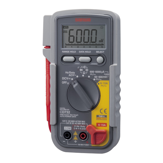
3-2 Multimeter, Test leads Holster(H-70) Test lead Display Wall Data hold hanger Range hold button button Select Continuity button lamp Stand Power switch Safety cover and function switch 6 ·15 A input terminal COM- input terminal V,Hz,Duty, Ω,● , ●, ,μA, mA input terminal ・... -
Page 7: Switches/Buttons And Description
【4】Description of Functions 4-1 Switches/buttons and description ○Power switch and function switch Turn this switch to turn on and off the power and to select the , μA, mA, A. functions of V, /●, Ω/● ○Range hold button Pressing this button once sets the manual mode and the range is fixed. -
Page 8: How To Use The Stand
○Auto power save This instrument incorporates the auto power save function that turns off the display in about 16 minutes to save the battery draining. When the rotary switch or a switch button is not controlled while this instrument is ON, the warning buzzer beeps in about 15 minutes and then the instrument power and display are turned off automatically in 1 minute after. -
Page 9: Start-Up Inspection
【5】MEASUREMENT PROCEDURE 5-1 Start-up Inspection WARNING 1. Never use meter if the meter or test leads are damaged or broken. 2. Make sure that the test leads are not cut or otherwise damaged. – 38 –... -
Page 10: Dc Voltage Measurement (Dcv)
5-2 DC voltage measurement (DCV) WARNING 1. Never apply a voltage signal exceeding the maximum rated input value. 2. Do not turn the rotary switch to change the function during measurement. 3. Always keep your fingers behind the finger guards on the test lead when making a measurement. -
Page 11: Ac Voltage Measurement (Acv)
5-3 AC voltage measurement (ACV) WARNING 1. Never apply a voltage signal exceeding the maximum rated input value. 2. Do not turn the rotary switch to change the function during measurement. 3. Always keep your fingers behind the finger guards on the test lead when making a measurement. -
Page 12: Line Frequency Measurement (Hz)
5-4 Line frequency measurement (Hz) WARNING 1. Never apply a voltage signal exceeding the maximum rated input value. 2. Do not turn the rotary switch to change the function during measurement. 3. Always keep your fingers behind the finger guards on the test lead when making a measurement. -
Page 13: Duty Ratio Measurement (Duty)
5-5 Duty ratio measurement (Duty) WARNING 1. Never apply a voltage signal exceeding the maximum rated input value. 2. Do not turn the rotary switch to change the function during measurement. 3. Always keep your fingers behind the finger guards on the test lead when making a measurement. -
Page 14: Resistance Measurement ( )
5-6 Resistance measurement ( ) WARNING Never apply an external voltage or current to the measurement terminals. Function Maximum rated input Ranges 600.0 . 6.00 k , 60.00 k , 600.0 k 60.00 M 6.000 M , 60.00 M Resistor Note: ●... -
Page 15: Diode Test ( )
5-7 Diode test ( WARNING Never apply an external voltage or current to the measurement terminals. Anode Press the SELECT button ● to switch to “ ”. Diode 0.556 Forward test Reverse test Note: ● The open voltage across the measurement terminals is about 2.7 V. -
Page 16: Circuit Continuity Check ( )
5-8 Circuit continuity check ( WARNING Never apply an external voltage or current to the measurement terminals. Press the SELECT button to switch to “ ”. Note: ● The open voltage across the measurement terminals is about 0.63 V. ● The continuity buzzer beeps and the continuity lamp lights when the resistance is between 10 and 60 Ω. -
Page 17: Capacitor Measurement
5-9 Capacitor measurement ( WARNING Never apply an external voltage or current to the measurement terminals. CAUTION 1. Discharge the measurement target capacitor before the measurement. 2. As this instrument measures the capacitance by applying current to the capacitor, it is not suitable for measuring an electrolytic capacitor with high leak current because of an increased error. -
Page 18: Current Measurement (Μa, Ma, A)
5-10 Current Measurement (μA, mA, A) WARNING (Applicable to both sections 5-10-1 and 5-10-2) 1. Never apply voltage to the input terminals. Power Power Load Load 〔×〕 〔○〕 Wrong connection Right connection 2. Be sure to make a series connection via load. (please see to above drawing) 3. -
Page 19: Dc/Ac Current (Dc/Ac A)
Resistor Battery Example of DC 60-600 mA range measurement Note: ● As this instrument employs the mean value method for the AC detection, measurements become erroneous when the input waveform is other than a sine wave (the frequency range is 45 to 500 Hz). ●... - Page 20 Function Maximum rated input Ranges 600.0 μA, 6000 μA 15 A DC/AC A + − Example of DC 6-15 A range measurement Note: ● As this instrument employs the mean value method for the AC detection, measurements become erroneous when the input waveform is other than a sine wave (the frequency range is 45 to 500 Hz).
-
Page 21: How To Use Optional Products
Connect the red plug of the current probe to the + measure- ment terminal and the black plug to the COM (−) terminal. Set the function switch of this instrument (CD732) to “ACV”. Set the range hold button to the 6 V range. -
Page 22: Measurement Using The Dc/Ac Current Probe (Cl-22Ad)
Connect the red plug of the current probe to the + measure- ment terminal and the black plug to the COM (−) terminal. Set the function switch of this instrument (CD732) to “DCV” for DCA measurement or “ACV” for ACA measurement. -
Page 23: Measurement Using The Dc Current Probe (Cl33Dc)
Connect the red plug of the current probe to the + measure- ment terminal and the black plug to the COM (−) terminal. Set the function switch of this instrument (CD732) to “DCV”. Set the range hold button to the DC 600 mV range. -
Page 24: Measurement Using The Dc High-Voltage Probe (Hv-60)
5-11-4 Measurement using the DC high-voltage probe (HV-60) Maximum measurable voltage: DC 30 kV WARNING 1. The HV probe is designed to measure low-current circuitry. Do not use it to measure high voltages of power transmission line, etc. 2. Do not apply a voltage higher than the maximum measur- able voltage (DC 30 kV) of the probe. -
Page 25: Maintenance
【6】MAINTENANCE WARNING 1. This section is very important for safety. Read and understand the following instruction fully and maintain your instrument properly. 2. The instrument must be calibrated and inspected at least once a year to maintain the safety and accuracy. 6-1 Maintenance and inspection 1. - Page 26 Factory -preinstalled built-in battery A battery for monitoring is preinstalled before shipping, therefore it may run down sooner than the battery life specified in the instruction manual. *The "battery for monitoring" is a battery to inspect the functions and specifications of the product. <How to replace the battery>...
-
Page 27: Cleaning And Storage
Battery(R6,1.5 V×2) ※There is a inside of Screw rear case. − + 16 A/1000 V Fuse 400 mA/1000 V Fuse 6-4 Cleaning and Storage CAUTION 1. The panel and the case are not resistant to volatile solvent and must not be cleaned with thinner or alcohol. For cleaning, use dry, soft cloth and wipe it lightly. -
Page 28: Specifications
【7】SPECIFICATIONS 7-1 Measurement Range and Accuracy Accuracy assurance range : 23±5 ˚C 80 %RH MAX. No condensaition. Input Impedance Function Range Accuracy Remarks ±(0.5 %rdg+2 dgt) 600.0 mV ≥100 M Ω Approx. 11 M 6.000 V Ω 60.00 V ±(0.9 %rdg+2 dgt) Approx. - Page 29 ◎Accuracy calculation method Example) DC voltage measurement (DC mV) True value: 100.0 mV Range accuracy: 600 mV range - ±(0.5 %rdg + 2 dgt) Tolerance: ±(100.0 [mV] x 0.5 % + 2 [dgt]) = ±0.7 [mV] Displayed value: 100.0 [mV] ± 0.7 [mV] (within the range of 99.3 to 100.7 mV) CAUTION: If there is presence of strong magnetic field generated by...
-
Page 30: General Specifications
7-2 General Specifications Measuring Method:△Σmethod Display : 6000 counts Range selection : Auto and manual ranges Over display : "O.L" is displayed (except DC/AC 15 A, DC 1000 V, AC 750 V ranges) Polarity : Automatic selection (only "−" is displayed) Battery discharge display : If the internal battery has been consumed and the voltage drops, the display shows. -
Page 31: After-Sales Service
· Carrying case C-SP 【8】After-Sales Service 8-1 Warranty and Provision Sanwa offers comprehensive warranty services to its end-users and to its product resellers. Under Sanwa's general warranty policy, each instrument is warranted to be free from defects in workmanship or material under normal use for the period of one (1) year from the date of purchase. -
Page 32: Warranty And Provision
3) Repair after the warranty period has expired: In some cases, repair and transportation cost may become higher than the price of the product. Please contact Sanwa authorized agent / service provider in advance. The minimum retention period of service functional parts is 6 years after the discontinuation of manufacture. - Page 33 MEMO – 62 –...
- Page 34 保証書 CD732 ご氏名 型 名 様 製造No. ご住所 この製品は厳密なる品質管理を経てお 届けするものです。 本保証書は所定項目をご記入の上保管 していただき、アフターサービスの際 ご提出ください。 ※本保証書は再発行はいたしませんの で大切に保管してください。 保証期間 本社 = 東京都千代田区外神田2−4−4 ・ 電波ビル ご購入日 年 月より 3 年間 郵便番号 = 101-0021・電話 = 東京 (03) 3253−4871 ( 代) 保証規定 保証期間中に正常な使用状態のもとで、万一故障が発生した場合には無償で修理いたし ます。ただし下記事項に該当する場合は無償修理の対象から除外いたします。 記 1. 取扱説明書と異なる不適当な取扱いまたは使用による故障...
- Page 36 本社 = 東京都千代田区外神田2−4−4 ・ 電波ビル 郵便番号 = 101-0021・電話 = 東京 (03) 3253−4871 ( 代) 大阪営業所 = 大阪市浪速区恵美須西2−7−2 郵便番号 = 556-0003・電話 = 大阪 (06) 6631−7361 ( 代) SANWA ELECTRIC INSTRUMENT CO.,LTD. Dempa Bldg, 4-4 Sotokanda2-Chome Chiyoda-Ku,Tokyo,Japan 植物油インキを使用しています。 01-1404 2040 2040...
Need help?
Do you have a question about the cd732 and is the answer not in the manual?
Questions and answers