Table of Contents
Advertisement
Advertisement
Table of Contents

Related Manuals for Sanwa CD770


Summary of Contents for Sanwa CD770
- Page 1 CD770 DIGITAL MULTIMETER INSTRUCTION MANUAL...
-
Page 2: Table Of Contents
6-2 Calibration and Inspection ⋯⋯⋯⋯⋯⋯⋯⋯⋯⋯⋯⋯⋯016 6-3 Storage ⋯⋯⋯⋯⋯⋯⋯⋯⋯⋯⋯⋯⋯⋯⋯⋯⋯⋯⋯⋯⋯016 6-4 Battery and Fuse Replacement ⋯⋯⋯⋯⋯⋯⋯⋯⋯⋯⋯016 7 After-Sale Service 7-1 Warranty and Provision ⋯⋯⋯⋯⋯⋯⋯⋯⋯⋯⋯⋯⋯⋯018 7-2 Repair ⋯⋯⋯⋯⋯⋯⋯⋯⋯⋯⋯⋯⋯⋯⋯⋯⋯⋯⋯⋯⋯018 7-3 SANWA web site ⋯⋯⋯⋯⋯⋯⋯⋯⋯⋯⋯⋯⋯⋯⋯⋯⋯019 8 SPECIFICATIONS 8-1 General Specifications ⋯⋯⋯⋯⋯⋯⋯⋯⋯⋯⋯⋯⋯⋯020 8-2 Measuring Range and Accuracy ⋯⋯⋯⋯⋯⋯⋯⋯⋯⋯021... -
Page 3: Safety Precautions - Before Use, Read The Following Safety Precautions
*Before use, read the following safety precautions. This instruction manual explains how to use your new digital multi meter CD770. Before use, please read this manual thoroughly to ensure correct and safe use. After reading it, keep it together with the product for reference to it when necessary. -
Page 4: Overload Protection⋯⋯⋯⋯⋯⋯⋯⋯⋯⋯⋯⋯⋯⋯⋯⋯002
04. Never use the meter for measuring voltages of lines connected to equipment (e.g. motors) that generates induced or surge voltage since it may exceed the maximum allowable overload input. 05. Never use the meter near equipment which generates strong electromagnetic waves or is charged. -
Page 5: Applications And Features
[2] APPLICATIONS AND FEATURES 2-1 Applications This is a digital multimeter designed for measurement of low- voltage circuits. This meter is useful for measuring / analyzing circuits of small communication devices, home electric appliances and batteries within the CAT. III environment. 2-2 Features •... -
Page 6: Names Of Component Units
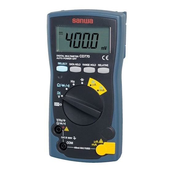
[3] NAMES OF COMPONENT UNITS 3-1 Meter Select button Range hold button Relative button Data hold button Power switch & function switch Safety cap Measuring terminal A/mA COM (common) terminal Measuring terminal 3-2 Test Leads Test pins Flanges Test probe (red) Plugs Test probe (black) —... -
Page 7: Display ⋯⋯⋯⋯⋯⋯⋯⋯⋯⋯⋯⋯⋯⋯⋯⋯⋯⋯⋯⋯⋯005
3-2 Display Indication of numerical value. Indication of relative mode operation. Indication of negative sign of numerical data. Indication of AC measuring function operation. Indication of DC measuring function operation. Indication of auto range mode operation. Not used with this meter. Indication of diode test function operation. -
Page 8: Description Of Functions
[4] DESCRIPTION OF FUNCTIONS 4-1 Power Switch & Function Switch Turn this switch to turn on and off the power and select a measuring function. 4-2 Measuring Function Selection: When the button is pressed, the functions change as follows: • V position: DC voltage ( AC voltage ( DC voltage ( •... -
Page 9: Relative Measurement
4-5 Relative Measurement: When the button is pressed, will light and the input value when the button was pressed will become 0 as the reference. To cancel it, press the button again. Example: Display after pressing the button at DC30.00V input Actual Input Value Value in Display DC 30.00V... -
Page 10: Measuring Procedure
[5] MEASURING PROCEDURE WARNING 1. Do not apply an input signal exceeding the maximum rated input of each function. 2. During measurement, do not change the function switch. 3. During measurement, do not touch the test pin side of the flange of the test lead. - Page 11 Always conduct the start-up inspection to ensure safety. (Inspection by the continuity check.) Inspection start Meter or Broken. test leads not broken? Check Not broken. Insert black plug of test lead to terminal and red plug to ) terminal. with function switch and select button.
-
Page 12: Voltage Measurement
5-2 Voltage Measurement ( Function Max. Rated Input Range DC 600V 400.0mV, 4.000V, 40.00V, 400.0V, 600V AC 600V 4.000V, 40.00V, 400.0V, 600V Example of DCV Example of ACV measurement measurement DCV and ACV Selection Remarks: This meter’s AC detection method is the average value method. It indicates an average value of voltage or current in the positive half cycle. - Page 13 5-3 Resistance Measurement ( ), Diode Test ( ), Continuity Check ( WARNING Never apply a voltage to the measuring terminals. 5-3-1 Resistance measurement ( Function Max. Rated Input Range 400.0Ω, 4.000kΩ, 40.00kΩ, 40.00MΩ 400.0kΩ,4.000MΩ, 40.00MΩ Caution: Resistor If measurement is affected by noises, shield the object to measure with COM potential.
-
Page 14: Resistance Measurement ( ), Diode Test ( )
5-3-3 Continuity check ( Remarks: Continuity buzzer sound range: Resistance 0 Ω ~ 85 Ω (±45 Ω) measurement Diode test Continuity check Selection 5-4 Frequency Measurement ( CAUTION Measurement prohibited Never use the meter for measuring frequencies to ground as the earth leakage breaker may trip. Function Max. -
Page 15: Capacitance Measurement
Remarks: • Input sensitivity: 3 Vrms or over. • Zero cross (+ potential - potential + potential) frequencies can be measured. Frequencies of + potential only or – potential only such as logic pulses cannot be measured. • Frequencies less than 1 Hz cannot be measured. •... -
Page 16: Current Measurement
5-6 Current Measurement (µA/mA) WARNING 1. Never apply a voltage to the measuring terminals. 2. Never apply an input exceeding the maximum rated current. 3. Be sure to connect the meter in series via a load. Correct measuring Wrong measuring method method Power supply... - Page 17 µA • mA measurement Function Input Terminal Built-in Fuse 0.5A/250VFuse Breaking capacity1.5kA • If the indication will change little when an input signal is applied or a current value which is significantly smaller than the expected value is indicated, possible causes are the input terminals, incorrect setting of the function switch, or blown fuse.
-
Page 18: Maintenance And Inspection ⋯⋯⋯⋯⋯⋯⋯⋯⋯⋯⋯⋯016
If any of the above problems exists, stop using the meter and request for repair. 6-2 Calibration and Inspection For more information, please contact Sanwa’s authorized agent / distributors, service provider, listed in our website. See section 7-3. 6-3 Storage CAUTION 1. - Page 19 WARNING 1. To avoid electric shock, do not remove the rear case with an input being applied to the measuring terminals. Also, before starting replacement, make sure the power of the meter is OFF. 2. Be sure to use the replacement fuse of the same rating. Never use a substitute for the fuse nor short the meter.
-
Page 20: After-Sale Service
(1) year from the date of purchase. This warranty policy is valid within the country of purchase only, and applied only to the product purchased from Sanwa authorized agent or distributor. Sanwa reserves the right to inspect all warranty claims to determine the extent to which the warranty policy shall apply. -
Page 21: Sanwa Web Site ⋯⋯⋯⋯⋯⋯⋯⋯⋯⋯⋯⋯⋯⋯⋯⋯⋯019
Please contact Sanwa authorized agent / distributor / service provider, listed in our website, in your country with above information. An instrument sent to Sanwa / agent / distributor without above information will be returned to the customer. Note: 1) Prior to requesting repair, please check the following: Capacity of the built-in battery, polarity of installation and discontinuity of the test leads. -
Page 22: Specifications
[8] SPECIFICATIONS 8-1 General Specifications Operation method - method AC measuring method Average value method 4000 counts Sampling rate Approx. 3 times/sec. Range selection Auto and Manual (Some with Manual only or Auto only) Over-range indication “OL” shown in numerical part. (600 V DC/AC excluded.) Polarity indication “... -
Page 23: Measuring Range And Accuracy ⋯⋯⋯⋯⋯⋯⋯⋯⋯⋯021
8-2 Measuring Range and Accuracy Temperature: 23±5˚C, humidity: 80% RH max. (no condensation), voltage 2.4 V or above. rdg (reading): Read value, dgt (digit): Number of counts of last digit Range Accuracy Input Resistance Remarks ±(0.5%rdg+2dgt) Approx. 100MΩ 400.0mV 4.000V Approx. - Page 24 Frequency Range Accuracy Remarks Auto range only. 5.000Hz The data hold and relative functions cannot be used. Sensitivity: 3 Vrms or over. 50.00Hz Frequency less than 1 Hz cannot be measured. 500.0Hz Input resistance Approx. 2 kΩ ±(0.3%rdg+3dgt) Because the input resistance is as low as approx.
- Page 25 * Accurate measurement may not be possible in places near a transformer, large-current line, etc. where a strong magnetic field is present or near radio equipment, etc. that generates a strong electric field. Accuracy calculation Example: DCV function True value: 100 mV Range accuracy: 400 mV range …±(0.5%rdg+2dgt) Error: ±(100.0mV x 0.5% + 2dgt) = ±0.7mV Indicated value: 100.0mV ±...
- Page 26 SANWA ELECTRIC INSTRUMENT CO.,LTD. Dempa Bldg., 4-4 Sotokanda2-Chome Chiyoda-Ku,Tokyo,Japan...
Need help?
Do you have a question about the CD770 and is the answer not in the manual?
Questions and answers