Table of Contents
Advertisement
Quick Links
Download this manual
See also:
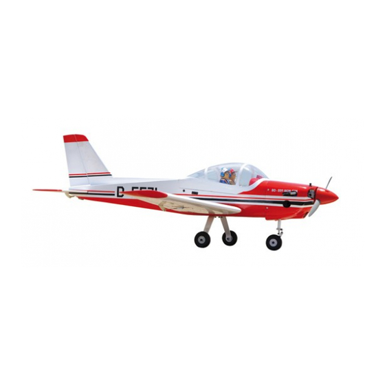
Instruction Manual Book
SPECIFICATION
Wingspan :
Length
Weight
Radio
Servo
Engine
Electric Motor: RIMFIRE.46.
Battery: 18.5 -22.2V(5-6S LIPO)
Propeller:11.5
Speed control: 60A.
Instruction Manual book
1,600 mm
:
1,184 mm
:
3.1 kg
:
5 channels.
:
04-05 servos
:
46- 2 stroke
9 CC Gas.
62.99 in.
46.61 in.
6.82Lbs.
Made in Vietnam.
ITEM CODE: BH120.
Advertisement
Table of Contents

Related Manuals for arf BO-209 MONSUN


Summary of Contents for arf BO-209 MONSUN
- Page 1 Instruction Manual book ITEM CODE: BH120. SPECIFICATION Wingspan : 1,600 mm 62.99 in. Length 1,184 mm 46.61 in. Weight 3.1 kg 6.82Lbs. Radio 5 channels.
- Page 2 BO - 209 MON SUN -Item code: BH120 INSTRUCTION MANUAL. This instruction manual is designed to help you build a great flying aeroplane. Please read this manual thoroughly before starting assembly of your AERO COMMANDER SHRIKE-EP. Use the parts listing below to identify all parts. WARNING.
-
Page 3: Safety Precaution
BO-209 MON SUN -Item code: BH120 INSTRUCTION MANUAL. Caution: this model is not a toy! Caution! do not heat the film more than is If you are a beginner to this type of powered absolutely necessary. If the air or the iron is model, please ask an experienced model flyer for help and support. -
Page 4: Installing The Aileron Servo
BO - 209 MON SUN -Item code: BH120 INSTRUCTION MANUAL. REPLACEMENT SMALL PARTS 3x20mm. 4x15mm. 4x15mm. 4x25mm. 1. Aluminium landing gear. 2. Wheels. Bottom side. 3. Nose gear set (with oleo struts) 4. Plastic - enginemount. 5. Fuel tank. 6. Spinner. 7.Engine mount ply of wood . - Page 5 BO-209 MON SUN -Item code: BH120 INSTRUCTION MANUAL. 2) Using a modeling knife, remove the cov- ering at possition show below. Remove C/A glue. covering Servo tray C/A glue. Top side. Servo tray C/A glue. Electric wire Top side. ...
- Page 6 BO - 209 MON SUN -Item code: BH120 INSTRUCTION MANUAL. 4) Drill 1,6mm pilot holes through the block 2.INSTALLING THE AILERON of wood for each of the four mounting screws CONTROL HORN. provided with the servo. Control horn of Aileron Electric wire Control horn.
-
Page 7: Option 1: Electric Motor
BO-209 MON SUN -Item code: BH120 INSTRUCTION MANUAL. THERE ARE TWO OPTIONS: 1. ELECTRIC MOTOR 2. ENGINE MOUNT. OPTION 1: ELECTRIC MOTOR INSTALLING ELECTRIC MOTOR. Aileron control horn. Repeat the procedure for the other wing half. 3x 15 mm 3.INSTALLING THE AILERON LINKAGES. - Page 8 BO - 209 MON SUN -Item code: BH120 INSTRUCTION MANUAL. Drill a hole 3mm diameter 3x 15mm Secure 3x 15mm Secure. Battery.
-
Page 9: Option 2: Engine Mount
BO-209 MON SUN -Item code: BH120 INSTRUCTION MANUAL. Drill a hole 4mm diameter OPTION 2: ENGINE MOUNT INSTALLING THE ENGINE MOUNT. Secure. See pictures below: 3x20mm 4 x 25 mm INSTALLING THE ENGINE. -
Page 10: Installing The Throttle Pushrod
BO - 209 MON SUN -Item code: BH120 INSTRUCTION MANUAL. 3 x 20mm Mark point. Secure. Right side Drill a hole 2.5mm diameter INSTALLING THE THROTTLE PUSHROD. Install one adjustable metal connector through the third hole out from the center of one servo arm, enlarge the hole in the servo arm using a 2mm drill bit to accommodate the servo connector. -
Page 11: Installing The Stopper Assembly
BO-209 MON SUN -Item code: BH120 INSTRUCTION MANUAL. Connector. FUEL TANK. Servo arm. INSTALLING THE STOPPER ASSEMBLY 1) The stopper has been pre-assembled at the factory. 2) Using a modeling knife, cut one length of silicon fuel line (the length of silicon fuel line is calculated by how the weighted clunk should rest about 8mm away from the rear of the tank and move freely inside the tank). - Page 12 BO - 209 MON SUN -Item code: BH120 INSTRUCTION MANUAL. Blow through one of the lines to ensure the fuel lines have not become kinked inside the fuel tank compartment. Air should flow through easily. 9. To secure the fuel tank in place, apply a bead of silicon sealer to the forward area of the tank, where it exits the fuselage behind the engine mounting box and to the rear of the tank...
-
Page 13: Nose Gear Installation
BO-209 MON SUN -Item code: BH120 INSTRUCTION MANUAL. NOSE GEAR INSTALLATION. Installing steering arm as follow Adjust the nose gear steering arm until the arm is parallel with the fire wall. - Page 14 BO - 209 MON SUN -Item code: BH120 INSTRUCTION MANUAL. Bottom side Secure 2. While keeping the back edge of the cowl flush with the marks, align the front of the cowl with the crankshaft of the engine. The front of the cowl should be positioned so the crankshaft is in nearly the middle of the cowl opening.
-
Page 15: Installing The Spinner
BO-209 MON SUN -Item code: BH120 INSTRUCTION MANUAL. Machine screw. Drill a hole 2mm diameter Font view INSTALLING THE SPINNER. Install the spinner backplate, propeller and spinner cone. The spinner cone is held in place using two 3mm x 12mm wood screws. 3 x 12mm Secure. -
Page 16: Installing The Main Landing Gear
BO - 209 MON SUN -Item code: BH120 INSTRUCTION MANUAL. Secure. Secure. 4x15mm Secure. INSTALLING THE MAIN LANDING GEAR. PARTS REQUIRED 1) Assemble and mounting the wheel pants as shown in the following pictures. - Page 17 BO-209 MON SUN -Item code: BH120 INSTRUCTION MANUAL. Secure. 2) A drop of C/A glue on the wheel collar screws will help keep them from coming lose during operation. Repeat the process for the other wheel. Bottom side ELEVATOR INSTALLATION. SERVO INSTALLATION.
-
Page 18: Horizontal Stabilizer
BO - 209 MON SUN -Item code: BH120 INSTRUCTION MANUAL. HORIZONTAL STABILIZER. Bottom side C/A glue. C/A glue. C/A glue. C/A glue. C/A glue. Bottom side C/A glue. -
Page 19: Elevator Control Horn Installation
BO-209 MON SUN -Item code: BH120 INSTRUCTION MANUAL. Epoxy glue. Bottom side Mark line. Epoxy glue. C/A glue. Bottom side. R e m o v e covering. ELEVATOR CONTROL HORN INSTALLATION. Elevator control horn install as same as the way of aileron control horn. Please see pic- tures below. -
Page 20: Vertical Installation
BO - 209 MON SUN -Item code: BH120 INSTRUCTION MANUAL. Bottom side. Epoxy PLUS glue VERTICAL INSTALLATION. Rudder servo install as same as method of elevator servo. See picture below: R u d d e r servo. E l e v a t o r pushrod ELEVATOR PUSHROD INSTALLATION. - Page 21 BO-209 MON SUN -Item code: BH120 INSTRUCTION MANUAL. C/A glue. C/A glue. C/A glue. Epoxy glue C/A glue. Epoxy glue...
-
Page 22: Rudder Pushrod Installation
BO - 209 MON SUN -Item code: BH120 INSTRUCTION MANUAL. C/A glue. Rudder control horn. C/A glue. RUDDER PUSHROD INSTALLATION. Rudder pushrod install as same as the way of aileron pushrod. M2 lock nut. RUDDER CONTROL HORN INSTALLA- TION. Rudder control horn install as same as the way of aileron control horn. -
Page 23: Installing The Switch
BO-209 MON SUN -Item code: BH120 INSTRUCTION MANUAL. INSTALLING THE SWITCH. 1. Cut out the switch hole using a modeling knife. Use a 2mm drill bit and drill out the two mounting holes through the fuselage side. ... -
Page 24: Wing Attachment
BO - 209 MON SUN -Item code: BH120 INSTRUCTION MANUAL. Tie wrap. Battery. Battery. Switch. Right side Receiver. WING ATTACHMENT. Locate the aluminium wing dihe- dral brace. 19mm aluminium tube 485 mm *** Test fit the aluminium tube dihedral brace into each wing haft. - Page 25 BO-209 MON SUN -Item code: BH120 INSTRUCTION MANUAL. WING ATTACHMENT. See picture wing attach to fuselage. Wing bolt. Top side. Left side BALANCING. 1) It is critical that your airplane be bal- anced correctly. Improper balance will cause your plane to lose control and crash.
-
Page 26: Control Throws
BO - 209 MON SUN -Item code: BH120 INSTRUCTION MANUAL. CONTROL THROWS. Accurately mark the balance point on the top of the wing on both sides of the fuselage. The 1) We highly recommend setting up a balance point is located 76mm back from the plane using the control throws listed.
Need help?
Do you have a question about the BO-209 MONSUN and is the answer not in the manual?
Questions and answers