Table of Contents
Advertisement
Quick Links
Advertisement
Table of Contents

Subscribe to Our Youtube Channel
Related Manuals for arf P-51 MUSTANG


Summary of Contents for arf P-51 MUSTANG
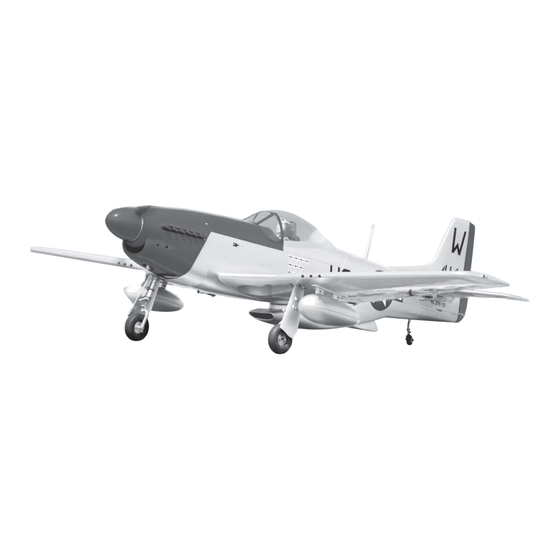
- Page 1 Instruction Manual book ITEM CODE:BH 140 SPECIFICATION Wingspan : 2,050mm 80.71 in. Length 1,840 mm 72.41 in. Weight 6.8kg 14.96 Lbs. Radio : 07 channels.
- Page 2 P-51 MUSTANG Instruction Manual Item code: BH140 This instruction manual is designed to help you build a great flying aeroplane. Please read this P-51-MUSTANG. manual thoroughly before starting assembly of your Use the parts listing below to identify all parts.
-
Page 3: Safety Precaution
P-51 MUSTANG Instruction Manual Item code: BH140 Caution: this model is not a toy! If you are a beginner to this type of powered model, please ask an experienced model flyer for help and support. If you attempt to operate the model without knowing what you are doing you could easily injure yourself or somebody else. - Page 4 P-51 MUSTANG Instruction Manual Item code: BH140 REPLACEMENT LARGE PARTS A. Cowling. F1. Aluminium tube wing dihedral brace. B. Wing panel(B1,B2). F2. Aluminium tube Horizontal stabilizer. C Fuselage. G. Decal sheet. D.Horizontal stabilizer(D1,D2). E. Rudder. K.Pilot REPLACEMENT SMALL PARTS 3x20mm 5.
-
Page 5: Installing The Aileron Servos
P-51 MUSTANG Instruction Manual Item code: BH140 7.Plastic parts for bottom fuselage. 8. Air tank. 9.Air line sets. 10.Fuel tank 11.3 way connector. 12.Valve one way. Aileron 13.Valve control. 14.Spinner 2) Using a modeling knife, remove the cov- 15.Battery tray. -
Page 6: Installing The Aileron Linkages
P-51 MUSTANG Instruction Manual Item code: BH140 3) Using the thread as a guide and using INSTALLING THE AILERON CONTROL HORN. masking tape, tape the servo lead to the end Aileron of the thread: carefully pull the thread out. - Page 7 P-51 MUSTANG Instruction Manual Item code: BH140 servo tray. Secure Bottom side Repeat the procedure for the other wing half. II. FLAP 1.INSTALLING THE FLAP SERVO 2x10mm. Secure. Flap. Bottom side...
- Page 8 P-51 MUSTANG Instruction Manual Item code: BH140 3.INSTALLING THE FLAP LINKAGES. Installing the flap linkages as pictures below. 60mm 3x10mm. 2.INSTALLING THE FLAP CONTROL HORN. Install flap control horn as same as picture below. Control horn Flap. Secure. A+B Epoxy PLUS glue Bottom side.
- Page 9 P-51 MUSTANG Instruction Manual Item code: BH140 INSTALLING AIR RETRACTABLE LANDING GEAR. PARTS REQUIRED 3x15mm. 5x45mm. 5x45mm. spring spring Drill a hole 3mm diameter...
- Page 10 P-51 MUSTANG Instruction Manual Item code: BH140 5x45mm. 3x15mm. Secure.
- Page 11 P-51 MUSTANG Instruction Manual Item code: BH140 Secure. 3x10mm. 3x6mm. Secure 3x6mm. S e c u r e 3x10mm. Drill a hole...
- Page 12 P-51 MUSTANG Instruction Manual Item code: BH140 Bottom side. 3x 15mm Aileron. Flap Installing plastic parts for bomb wing. Secure. 3x20mm. Secure. Secure.
-
Page 13: Installing The Engine Mount
P-51 MUSTANG Instruction Manual Item code: BH140 INSTALLING THE ENGINE. Bottom side 5x70mm Repeat the procedure for the other wing half. INSTALLING THE ENGINE MOUNT. See pictures below: Front view. Secure. Drill a hole 6mm diameter INSTALLING THE THROTTLE PUSHROD. -
Page 14: Installing The Stopper Assembly
P-51 MUSTANG Instruction Manual Item code: BH140 After installing the adjustable metal con- nector apply a small drop of thin C/A to the bottom nut. This will prevent the con- nector from loosening during flight. Throttle servo. C u t Throttle servo. - Page 15 P-51 MUSTANG Instruction Manual Item code: BH140 8) Feed three lines through the fuel tank When the stopper assembly is installed in the tank, the top of the vent tube should rest just compartment and through the pre-drilled hole below the top surface of the tank.
- Page 16 P-51 MUSTANG Instruction Manual Item code: BH140 Left side Pushrod Choke. Fuel tank. Pushrod Choke. COWLING. 1. Slide the fiberglass cowl over the en- gine and line up the back edge of the cowl with the marks you made on the fuselage.
- Page 17 P-51 MUSTANG Instruction Manual Item code: BH140 Bottom side 3x 12mm Trim and cut Secure. 3. Slide the cowl back over the engine and secure it in place using four wood screws. Secure. Right side. Left side. Bottom side...
-
Page 18: Installing The Spinner
P-51 MUSTANG Instruction Manual Item code: BH140 Front view. INSTALLING THE SPINNER. Install the spinner backplate, propeller and spinner cone. The spinner cone is held in place using two 3mm x 8mm machine screws. Aluminium 10mm 5x50mm. Secure. Secure... -
Page 19: Installing The Elevator Servos
P-51 MUSTANG Instruction Manual Item code: BH140 INSTALLING THE ELEVATOR Right side SERVOS. 1. Install the rubber grommets and brass collets into the elevator servo. Test fit the servo into the servo tray. 2. Mount the servo to the tray using the mounting screws provided with your radio system. -
Page 20: Elevator Pushrod Installation
P-51 MUSTANG Instruction Manual Item code: BH140 A+B Epoxy PLus glue Bottom side. 4x15mm Secure Bottom side Elevator control horn ELEVATOR PUSHROD INSTALLATION. Elevator pushrod install as same as the way of aileron pushrod. M2 lock nut. ELEVATOR CONTROL HORN INSTALLATION. -
Page 21: Rudder Installation
P-51 MUSTANG Instruction Manual Item code: BH140 E l e v a t o r pushrod Cut. Elevator pushrod Elevator pushrod Bottom side bend 90 E l e v a t o r degree. pushrod RUDDER INSTALLATION. Rudder servo install as same as method of elevator servo. -
Page 22: Rudder Control Horn Installa- Tion
P-51 MUSTANG Instruction Manual Item code: BH140 Aluminium R u d d e r s e r v o Aluminium Rudder. Cut. A+B Epoxy PLus glue RUDDER CONTROL HORN INSTALLA- TION. Rudder control horn install as same as the way of aileron control horn. Please see pic- tures below. -
Page 23: Rudder Cable Installation
P-51 MUSTANG Instruction Manual Item code: BH140 RUDDER CABLE INSTALLATION. 1. Rudder push - pull system install as same as picture below. A+B Epoxy PLus glue Control horn Rudder. Bottom side. -
Page 24: Mounting The Tail Wheel Bracket
P-51 MUSTANG Instruction Manual Item code: BH140 MOUNTING THE TAIL WHEEL BRACKET. 1. Set the tail wheel assembly in place 3x15mm on the plywood plate. The pivot point of the tail wheel wire should be even with the rud- der hinge line and the tail wheel bracket should be centered on the plywood plate. - Page 25 P-51 MUSTANG Instruction Manual Item code: BH140 bottom side Top side Push-pull cable tail gear. Plastic parts of elevator pushrod and rudder cable. NSTALLING SERVO USING FOR VALVE CONTROL. valve control servo. Cut. C/A glue.
- Page 26 P-51 MUSTANG Instruction Manual Item code: BH140 Valve control Valve control servo. Air tank Air supply Valve one way Secure Right main gear wing Left main gear wing Valve control INSTALLATION AIR TANK Valve control Air tank...
- Page 27 P-51 MUSTANG Instruction Manual Item code: BH140...
-
Page 28: Installing The Switch
P-51 MUSTANG Instruction Manual Item code: BH140 Tie wrap S w i t c h Engine Tie wrap Switch Receiver. Air tank INSTALLING THE RECEIVER AND BATTERY. 1. Plug the servo leads and the switch lead into the receiver. -
Page 29: Wing Attachment
P-51 MUSTANG Instruction Manual Item code: BH140 Battery of receiver Battery tray Receiver WING ATTACHMENT. Locate the aluminium wing dihedral brace. C/A glue. Aluminium tube. 25 mm 762 mm *** Test fit the aluminium tube dihedral brace B a t t e r y into each wing haft. - Page 30 P-51 MUSTANG Instruction Manual Item code: BH140 3.Insert two wing panels as pictures below. Right wing. Left wing.
-
Page 31: Installing Cockpit Fuselage
P-51 MUSTANG Instruction Manual Item code: BH140 INSTALLING COCKPIT FUSELAGE . See picture below: See picture wing attach to fuselage. A +B Epoxy Installing the fuselage hatch as same as pic- PLUS glue ture below. - Page 32 P-51 MUSTANG Instruction Manual Item code: BH140 Antenna Front view. Left side. Right side. Front view. Secure. Installing plastic bottom fuselage. bottom side. A+B EPOXY gun set for wing PLUS GLUE C/A glue.
-
Page 33: Control Throws
P-51 MUSTANG Instruction Manual Item code: BH140 With the wing attached to the fuselage, all parts of the model installed ( ready to fly), and empty fuel tanks, hold the model at the marked balance point with the stabilizer level. -
Page 34: Pre-Flight Check
P-51 MUSTANG Instruction Manual Item code: BH140 15 mm 15mm 35mm 20mm 20mm 30mm 30mm PRE-FLIGHT CHECK. 1) Completely charge your transmitter and receiver batteries before your first day of fly- ing. ...
Need help?
Do you have a question about the P-51 MUSTANG and is the answer not in the manual?
Questions and answers