Advertisement
Quick Links
Advertisement

Related Manuals for arf MX2 50CC V2


Summary of Contents for arf MX2 50CC V2
- Page 1 ARF MODEL MX2 50CC V2 Instruction Manual...
- Page 2 Dear Customer, Thanks for purchasing this newly designed MX2 50CC V2 aerobatic RC airplane. The weight is approximately 17Lbs. It’s good for IMAC and free style flying. It’s a beautiful plane with amazing flight performance. It’s covered with genuine monocote, and comes with good quality accessories, including carbon fiber wing tube, Anodized 6061 aluminum landing gear or carbon fiber as an option.
-
Page 3: Specifications
ARF MODELS WARRANTY AND RETURN POLICY We guarantee that the plane is in perfect condition at purchase. The warranty will be voided after modifications and usages. If you have any questions or find any issues, please contact the distributors in your area. - Page 4 Includes Side Force Generator’s(SFG) CNC anodized aluminum Canopy Bolts Full length Tuned pipe tunnel designed into fuselage...
- Page 5 Anodized aluminum Long servo arms included Adjustable pushrods for easy fine tuning(Includes wrench) Servo extension safety connector clips High performance cap head bolts...
- Page 6 Flat nylon hinges for increased strength Honeycomb board carton packing for safer transportation High quality 3mm ball links assembly New dual fiberglass horn assembly...
- Page 7 New Carbon fiber tail wheel assembly High-quality durable rubber wheels Improved new Axles (the material of the Axle is stainless steel )
- Page 8 Two options for landing gear: Anodized 6061 Aluminum or Carbon fiber Carbon fiber landing gear Increased diameter carbon fiber wing tube than previous V1 version. Carbon fiber stab tube...
- Page 9 Scheme A White/black/green...
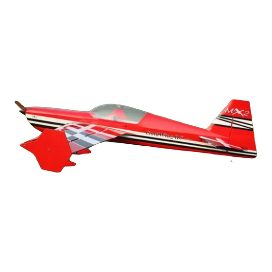
- Page 10 Scheme C Red/white/black...
- Page 11 Items Required to Complete This Model: Two switches with charging jacks for the Rx 50-70CC Gas engine and exhaust Two high quality Rx batteries of significant Appropriate propeller for your Motor capacity to power your choice of servos. ...
- Page 12 3. Some modelers prefer to seal the hinge gaps using strips of appropriate covering or clear trim tape. We have found this to be helpful with models intended for higher speed flight or models with unusually large hinge gaps. aircraft utilize a very tight double beveled hinge line and do not normally require this step.
- Page 13 Pushrods(Bag No. KA05CBG3) Four 3x60mm pushrods for ailerons. One 3x165mm pushrods rudder (Pull-push style) Pull-pull assembly kits for the rudder. (Bag No. KA05CD) Ball link assemblies (Bag No. KAG00131): 8 for ailerons and elevators.
- Page 14 Alu long arm kits (Bag No. KA05CC): 4 single arms for ailerons and elevators. 1 dual arm for the rudder. 6 Servo extension safety connector clips (Bag No. KAG0021) Main rubber wheels (Bag No. KAG014B):2PCS New stainless steel Axle kits (Bag No. KA05CH): 2PCS...
- Page 15 New Carbon fiber tail wheel assembly. (Bag No. KAG0104) Side force generators (4 x 3x20mm hex bolts & 4 x washers & 2 balsa sheet) Bolts for landing gear: 4(4x20mm) & 4 washers& 4mm stainless steel Self-locking nuts Hexagon bolts Bolts &...
-
Page 16: Wing Assembly
5 allen keys(Bag No. KA05CE) Wing Assembly NOTE: There are pictures of different planes in this manual, however, this plane’s wings is assembled the same way. 1.Aileron push rod linkage set. 3x60mm Pushrods for aileron. 2.It is much easier to install the twin control horns before installing the wing. Locate the fiberglass aileron control horns, ball links, and associated bolts and nylon-insert lock nuts. - Page 17 Slide the control horns in place and make sure they are centered perfectly by using a ruler to measure between the pivot holes and the hinge line. Wipe any excess glue off with isopropyl alcohol and paper towels. Install the ball links, bolts and nuts into the holes to help assure alignment of both control horns while the glue cures.
-
Page 18: Elevator Assembly
neutral. Double check all screws, bolts and nuts to assure proper installation and operation without binding.Once satisfied, permanently attach the ball link to the servo arm with the supplied screw and nut. 11. Check the final radio operation of the ailerons and make sure there is no binding or servo fighting of each other. - Page 19 3. Sand the area on the horn that will be glued inside the elevator. 4. Using plenty of 30 minute epoxy fit the horn and plate into place. Use a ball joint and bolt to hold the horn in place while drying. REPEAT FOR THE OTHER SIDE 5.
- Page 20 6. Place the servo into the elevator and screw in place. Remember to harden the holes with thin Cyano. 7. Place the servo arm back onto the servo, remembering to centre. Use nutlock on the servo arm screw. 8. Fit the pushrod in place remembering one end is reverse threaded. Set it so the arm is centered and the elevator is flat.
-
Page 21: Rudder Assembly
Use the wrench to adjust the pushrod to the appropriate length. Rudder Assembly NOTE: There are pictures of different planes in this manual, however, this plane’s rudder is assembled the same way. 1. Install the fiberglass control horns in the same way as you did the elevator horns. - Page 22 2.The MX2 is supplied with a high quality set of pull-pull cables and ball-links. 3.Locate the pull-pull cable set, threaded couplers, brass swaging tubes, and ball-links. If the cable is one long piece, cut it into two equal length pieces. Thread one end of the one cable through a brass tube and then through one of the threaded couplers.
- Page 23 7. The MX2 also provides pull-push style for rudder. Below is picture of pull-push style linkage set. Cut off excess fiberglass rudder horn, and use sandpaper to roughen up the parts needed to inlay. Use epoxy glue to glue the rudder horn.
-
Page 24: Tail Wheel Installation
Use 3x165mm push rod between the servo and the rudder horn. Then use the wrench to adjust the pushrod to the appropriate length. Tail Wheel Installation... - Page 25 1. Begin the tail wheel assembly by installing the hollow hex bolt and lock nut into the large hole at the rear of the tail wheel bracket. 2. Slide 3 wheel collars and the wheel onto the pre-bent tail wheel wire and tighten in place with thread lock as shown below.
- Page 26 4.There are 3 pre-installed blind nuts on the rear of the fuselage, locate the screw holes and puncture the covering. Then install the CF tail wheel bracket with M3 hex bolts and washers. 5.Drill a screw hole on the bottom of rudder, 200-220 mm away from the hinge line, with 2 mm drill bit. Secure one end of the wheel spring with a M3 12mm self-threaded screw, then hook the other end onto the steering rod.
-
Page 27: Main Landing Gear Installation
6.Fully installed tail wheel assembly is shown below. Main Landing Gear Installation NOTE: There are pictures of different planes in this manual, however, this plane’s landing gear is assembled the same way. 1. Locate the supplied main landing gear parts and sort them out on your workbench. - Page 28 2. Bolt the main gear to the bottom of the fuselage using the supplied bolts. Place the nuts in through the can tunnel opening with appropriate size spanner. Remember the gear will rake forward. 3. Loosen out the second nut, then apply 30 minute epoxy glue on the axle. Tighten the nut back in place, allow at least 1 hours for threadlocker to dry.
- Page 29 4. Install the main wheel axles to the composite landing gear and tighten the nylon-insert lock nut. Install one wheel collar onto the axle. Use a second wheel collar as a guide to leave a gap on the inboard of the axle.
- Page 30 Notice that the engine center line is offset to the left to compensate for the right thrust built into the engine box. 2. Fit the Cowl and measure the distance from the engine bulkhead to the front of the cowl, add approx 2-3mm for the back plate and this is the length that your engine should be set Using the correct length stand offs, mount your engine securely using bolts, washers, and locknuts.
- Page 31 5. An extra servo can be fitted for choke or a mechanical linkage can be used. 6. The fuel tank is preassembled. Complete the installation in the fuselage using zip ties or velcro straps to hold the tank in position. Connect a fuel line between the tank and carb, a fuel line between the tank vent and the bottom of the fuselage, and a fill line to a fueling port which can be mounted on the fuselage side opposite your ignition switch.
- Page 32 A barb on the bottom of the fuselage can be fitted for the vent. 7. The MX2 comes with canister pipe tunnel. Standard muffler, pitts muffler, canister or tuned pipe can be fitted. If a tuned pipe is going to be used the end of the can tunnel can be removed. The tunnel can be closed off to accept canisters of all sizes, or stock mufflers.
-
Page 33: Cowling Installation
Tuned Pipe Mounting The MX2 comes with many openings for the exhaust outlet, line up the exhaust then remove the covering for the required outlet. They come with covers that can be used for cooling. Use a soldering iron to open up the holes. - Page 34 2. Mark onto the cowel the area to remove, and remove with a dremel. As the MX2 has a scale inlet, depending on your engine it may need to be removed. If it is still attached it may be beneficial to strengthen with a small amount of glass cloth. ...
- Page 35 3.The cowl is secured with four 3 X 16mm bolts and washers. Apply nutlock onto the bolts as the vibration from the gas engine will shake them come loose.
- Page 36 FINAL RADIO SYSTEM INSTALLATION 1. Whether you 72 MHz systems or the newer 2.4 GHz systems, proper radio installation and care is vital to the safe and reliable operation of your aircraft. Follow the manufacturer’s instruction for installation guidance of receivers and batteries paying attention to factors such as vibration isolation, adequate cooling, and clearances.
- Page 37 Recommended control surface deflections: Low Rate High Rate Elevator 15 degrees 45-50 degrees Rudder 25 degrees 40-45 degrees Ailerons 25 degrees 35-40 degrees Use exponential on the dual rates at levels that suit your flying style. If you find that you require tail weight and cannot move parts around the aircraft a rear hatch has been added. Glue in the inner ring, once the covering has been removed.
- Page 38 Then install pull-pull ball links on control horns. 3.Installation of Elevators Connect extension servo wire, secure with safe clips. Attach elevators with 3X12mm Hex-head bolts and washers. 4.Install the wings onto the fuselage being careful to align the wing tube with the wings and not force it. The wing tube may be initially tight but will loosen some with use.
- Page 39 5. Side force generators Assembly. Cut the wing film needed to be instal the SFG. Fixed the SFG Use M3X20 cap head bolts and washers and balsa sheet. 6. Fill your fuel tank making sure your vent line is not plugged or capped. With the canopy off, this is a good time to check for any fuel leaks.
- Page 40 8. If you have removed your horizontal stabilizers, install them once again and check all bolts and connections. 9. Check all control surfaces for secure hinges by performed a slight tug on the control surfaces and observing if there is any give in the hinges. Check all control rods, ball links, servo screws, etc. for proper operation and installation.
- Page 41 For JR servo(23T): 47mm/1.75in Single No. KAG0S73J 100mm/4in Dual No. KAG0D73J * 3.5in C.F Spinner No. KAG0135 * Wingbags for 50CC No. KAG0094...
Need help?
Do you have a question about the MX2 50CC V2 and is the answer not in the manual?
Questions and answers