
Related Manuals for arf YAK 55M


Summary of Contents for arf YAK 55M
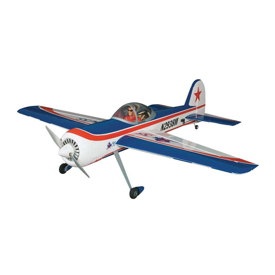
- Page 1 Instruction Manual book ITEM CODE: BH111 SPECIFICATION Wingspan : 1,810 mm. 71.26 in. Length 1,600 mm. 62.99 in. Weight 4.6kg. 10.12 lbs. Radio 6 channels. Servo 06 servos. Engine 30 cc Made in Vietnam.
-
Page 2: Instruction Manual
Instruction Manual ITEM CODE:BH111. This instruction manual is designed to help you build a great flying aeroplane. Please read this manual thoroughly before starting assembly of your YAK 55M. Use the parts listing below to identify all parts. WARNING. Please be aware that this aeroplane is not a toy and if assembled or used incorrectly it is capable of causing injury to people or property. -
Page 3: Safety Precaution
YAK 55 - Instruction Manual ITEM CODE:BH111. Caution: this model is not a toy! Caution! do not heat the film more than is If you are a beginner to this type of powered absolutely necessary. If the air or the iron is model, please ask an experienced model flyer too hot, the film may melt and holes may be for help and support. - Page 4 YAK 55 - Instruction Manual ITEM CODE:BH111. REPLACEMENT SMALL PARTS 1. Aluminium landing gear. INSTALLING THE AILERON SERVOS. 2. Wheels. 1. Install the rubber grommets and brass eyelets onto the aileron servo. 3. Spinner. 4.Engine mount ply of wood . 5.
-
Page 5: Installing The Aileron Linkages
YAK 55 - Instruction Manual ITEM CODE:BH111. 4) Drill 1,6mm pilot holes through the block of wood for each of the four mounting screws provided with the servo. Electric wire Aileron Control horn. 3.INSTALLING THE AILERON LINKAGES. Installing the aileron linkages as pictures below. -
Page 6: Installing The Engine Mount
YAK 55 - Instruction Manual ITEM CODE:BH111. After installing the adjustable metal con- INSTALLING THE ENGINE MOUNT. nector apply a small drop of thin C/A to See pictures below: the bottom nut. This will prevent the con- nector from loosening during flight. Throttle servo Drill a hole 4mm diameter. - Page 7 YAK 55 - Instruction Manual ITEM CODE:BH111. MAIN GEAR INSTALATION. PARTS REQUIRED 1) Assemble and mounting the wheel pants as shown in the following pictures. Engine mount ply of wood . 3 x 12mm. Secure. Secure. Secure. Left side. Secure. L a n d i n g gear.
- Page 8 YAK 55 - Instruction Manual ITEM CODE:BH111. 3) Carefully bend the second nylon tube up at a 45 degree angle (using a cigarette lighter). This tube will be the vent tube to the muffler. 4) Carefully bend the third nylon tube down at a 45 degree angle (using a cigarette lighter).
- Page 9 YAK 55 - Instruction Manual ITEM CODE:BH111. 6) When satisfied with the alignment of the stopper assembly tighten the 3mm x 20mm machine screw until the rubber stopper ex- pands and seals the tank opening. Do not over tighten the assembly as this could cause the tank to split.
- Page 10 YAK 55 - Instruction Manual ITEM CODE:BH111. Drill a hole 2.5mm diameter. 4. Install the muffler and muffler extension onto the engine and make the cutout in the cowl for muffler clearance. Connect the fuel and pressure lines to the carburetor, muffler and fuel filler valve.
-
Page 11: Installing The Spinner
YAK 55 - Instruction Manual ITEM CODE:BH111. INSTALLING THE SPINNER. Secure. Install the spinner backplate, propeller and spinner cone. The spinner cone is held in place using two 3mm x 12mm wood screws. Secure. Secure. Secure. Machine screw. Front view. -
Page 12: Horizontal Stabilizer
YAK 55 - Instruction Manual ITEM CODE:BH111. HORIZONTAL STABILIZER. 9 mm See pictures below: 247 mm 3 x 15 mm Right side. Left side. Bottom side. 3 x 15mm Secure... -
Page 13: Vertical Installation
YAK 55 - Instruction Manual ITEM CODE:BH111. 2x8 mm. Secure 130 mm Secure Secure ELEVATOR CONTROL HORN AND ELEVATOR PUSHROD INSTALLATION. Secure 3 x 25 mm. Elevator Elevator pushrod pushrod Bottom side. VERTICAL INSTALLATION. Rudder servo install as same as method of elevator servo. - Page 14 YAK 55 - Instruction Manual ITEM CODE:BH111. RUDDER CONTROL HORN INSTALLA- Aluminium TION. Rudder control horn install as same as the way of aileron control horn. Please see pic- tures below. 3 x 35 mm Control horn of Rudder. Cut. A+B PLUS glue A+B PLUS Glue.
-
Page 15: Mounting The Tail Wheel Bracket
YAK 55 - Instruction Manual ITEM CODE:BH111. RUDDER CAPLE INSTALLATION. 1. Rudder pushrod install as same as the way of aileron control horn. 2. Rudder push - pull system install as Secure. same as picture below. 2 x 8mm Secure. Elevator pushrod E l e v a t o r pushrod... - Page 16 YAK 55 - Instruction Manual ITEM CODE:BH111. Drill 2.5mm hole. Bottom side. E l e v a t o r E l e v a t o r pushrod pushrod Rudder cable Rudder cable INSTALLING THE SWITCH. 1) Cut out the switch hole using a modeling knife.
-
Page 17: Wing Attachment
YAK 55 - Instruction Manual ITEM CODE:BH111. INSTALLING THE RECEIVER AND BATTERY. 1. Plug the servo leads and the switch lead into the receiver. You may want to plug an aileron extension into the receiver to make plugging in the aileron servo lead easier when you are installing the wing . - Page 18 YAK 55 - Instruction Manual ITEM CODE:BH111. 4 x 40mm Secure. Secure. Top side BALANCING. 1) It is critical that your airplane be bal- anced correctly. Improper balance will cause your plane to lose control and crash. THE CENTER OF GRAVITY IS LOCATED 135MM BACK FROM THE LEADING EDGE Left wing OF THE WING.
-
Page 19: Pre-Flight Check
We wish you many safe and enjoy- 1. We highly recommend setting up a plane using the control throws listed. able flights with your YAK 55M. 2. The control throws should be meas- ured at the widest point of each control sur- face.
Need help?
Do you have a question about the YAK 55M and is the answer not in the manual?
Questions and answers