Table of Contents
Advertisement
Quick Links
Advertisement
Table of Contents

Related Manuals for CAME BX-246V


Summary of Contents for CAME BX-246V
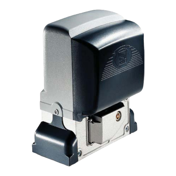
- Page 1 SLIDING 11 9 BF03EN GATES OPERATORS INSTALLATION MANUAL BX-246V English...
-
Page 2: Read Carefully
• This product should only be used for the purpose for which it was instructions • If the power cable is damaged, it must be replaced by the explicitly designed. Any other use is considered dangerous. CAME Cancelli manufacturer or the technical assistance service or by a person with a Automatici S.p.A. - Page 3 For intensive use and apartment-blocks. maximum weight and length of the gate are 600 kg and 18 m respectively. Legislative references Came Cancelli Automatici employs an ISO 9001 certified quality-management system and an ISO 14001 environmental-management system. Came engineers and manufactures entirely in Italy in compliance with the applicable safety regulations.
-
Page 4: Description Of Parts
Description of parts 1- Top cover 2 - Adjustments cover carter 3 - Electric card rack 4 - Endstop tabs 5 - Electronic card 6 - Front cover of the control panel 7 - - Access fl ap for reaching the release 8 - Anchoring plate 9 - Fastening bolts 10 - Plate for fastening bolts... -
Page 5: Tools And Equipment
Tools and equipment Make sure you have all the tools and materials needed to carry out the installation in total safety and in accordance with current regulations. The figure shows some examples of the tools needed by installers. 5.3 Cable types and minimum thickness Cable length Cable length Cable length... - Page 6 Fastening the plate and fi tting the operator The following illustrations are just examples, in that, the space for securing the operator and accessories varies depending on the overall measurements. It is up to the installer to choose the most suited solution. - Dig a pit at the end of the gate (see measurement quotas in drawing).
- Page 7 - For positioning the plate with respect to the rack, see and follow the instructions in the drawing. Fill the wooden form with concrete and wait at least 24 hrs for it to solidify. - Remove the wooden frame, use earth to fi ll the pit around the cement block. - Unscrew the washers and nuts from the bolts.
- Page 8 - Remove the cover of the gearmotor by turning the lateral screws. Position the gearmotor onto the plate. Warning! The electrical cables must pass through the inside of the gearmotor box. - Lift the gearmotor from the anchoring base by between 5 and 10 mm by turning the threaded-steel feet to allow room any later adjustments between pinion and rack.
- Page 9 - Manually open and close the gate and adjust the distance of the pinion-rack coupling by acting on the threaded-steel feet (vertical adjustments) and the slots (horizontal adjustments). This helps prevent the weight of the gate from bearing down on the operator. Rack Rack Pinion...
-
Page 10: Manually Releasing The Gearmotor
Fastening the endstop strips Position the endstop tabs onto the rack and fasten them with the 3 mm Allen wrench key. Their position, marks the limit of the gate runs. Note: avoid that the gate strikes the mechanical stop, whether when closing or opening. Mechanical stop 5.7 Manually releasing the gearmotor - Insert the key into the lock and turn it clockwise, .. - Page 11 Electronic card General description Power the electronic card with 230 V AC on terminals L-N, with a max frequency of 50/60 Hz. the command devices and accessories are powered by 24 V. Warning! The accessories must not exceed 35 W overall. The card is fi...
-
Page 12: Main Component Parts
Main component parts 1) Power source terminals 2) Endstop terminals 10 11 E1 1 2 3P 5 7 2 C1 C3 C7 C8 TS L2T L1T 0 17 26 FC FA F 3) Motor terminals 4) Encoder terminals 5) Accessories fuse 10 11 E1 1 2 3P 5 7 2 C1 C3 C7 C8 TS L2T L1T... - Page 13 Accessories power source Eyelet terminal with screw and washer for ground connection Terminals for powering accessories: - for 24 V AC at normal operation; - when emergency batteries are operating; Overall allowed power: 35 W 230 V AC powered, 50 / 60 Hz frequency Command devices Stop button (N.C.
- Page 14 Safety devices DIR / DELTAS photocells (N.C.) "partial stop" contact - Input for safety devices like photocells, compliant with law EN 12978. Stops gate if it is moving and then automatically closes it (if this function is selected). DIR / DELTAS photocells "Reopening while closing"...
- Page 15 DF with control card for DFI con- "Reopening when closing" (N.C.) Contact nections - Input for safety devices like sensitive edges, compliant with EN 12978 law. While the gate is closing, opening the contact will invert movement until it is fully opened;...
- Page 16 Adjustments 3 4 5 6 7 8 9 10 SLOW V. RUN V. SLOW S. RUN S. PAR.OP. A.C.T. ADJUSTMENT TRIMMER LIST : - «A.C.T.» Adjusts opening waiting time. The gate closes automatically once this time-frame has elapsed. The waiting time may be adjusted from 1 second to 150 seconds.
-
Page 17: Selecting Functions
Selecting functions Default setting 3 4 5 6 7 8 9 10 1 ON - Automatic closing - The automatic closing timer activates at the closing endpoint. The pre-set time is adjustable, but it's in any case subject to any safety device intervention and does not activate after a total "stop" or in case of power failure. 2 ON - "Open-stop-close-stop"feature with (2-7) button and radio transmitter (fi... -
Page 18: Activating The Radio Command
Activating the radio command Antenna Connect the RG58 antenna cable to the apposite terminals. 10 11 E1 1 2 3P 5 7 2 C1 C3 C7 C8 TS FC FA F 10 11 E1 1 2 3P 5 7 2 C1 C3 C7 C8 TS FC FA F C. - Page 19 ATOMO AT01 • AT02 see instruction sheet in the packaging AT04 of the AF43SR radio-frequency card Memorisation Keep the PROGbutton pressed on the electronic card. The LED fl ashes ON and OFF. 10 11 E1 1 2 3P 5 7 2 C1 C3 C7 C8 TS L2T L1T 0 17 26...
- Page 20 Connecting two coupled gearmotors having a single control With two coupled gearmotors, you can command only the opening (by button and/or radio control): the gate will close only in automatic closing mode. • Coordinate the direction of travel of the two gearmotors , by modifying the motor's rotation (invert the cables on terminals FA-FC and M-N).
-
Page 21: Safety Instructions
Safety instructions Important general safety instructions This product is only intended to be used for the purpose it was designed. Any other use is therefore improper and dangerous. The manufacturer is not liable for any damage caused by improper, wrongful or unreasonable use. Work well away from the gate hinges or mechanical moving parts. -
Page 22: Troubleshooting
Maintenance Periodic maintenance Periodic servicing performed by end-user are wiping clean the photocell's glass front pieces and checking for proper working state of safety devices and that the operator is free of any obsta- cles. We also suggest to periodically check the state of lubrication and tightness of screws on the operator. - Page 23 UNI EN ISO 14001 standard to ensure environmental protection. Please help us to safeguard the environment. At CAME we believe this to be one of the fundamentals of ours market operations and development strategies. Just follow these short disposal instructions: DISPOSING OF THE PACKAGING The components of the packaging (i.e.
- Page 24 HR • Za sve dodatne informacije o poduzeću, proizvodima i tehničkoj podršci: UK • Для отримання будь-якої іншої інформації про компанію, продукцію та технічну підтримку: www. came.com www. came.com CAME Cancelli Automatici S.p.a. CAME Cancelli Automatici S.p.a. Via Martiri Della Libertà, 15 31030 Dosson Di Casier...
Need help?
Do you have a question about the BX-246V and is the answer not in the manual?
Questions and answers