
Related Manuals for CAME BXV10AGF


Summary of Contents for CAME BXV10AGF
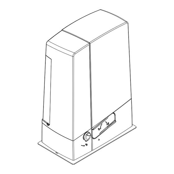
- Page 1 Sliding gate operator FA01719-EN BXV Rapid series BXV04AGF / BXV06AGF / BXV10AGF BXV06RGF / BXV10RGF INSTALLATION MANUAL EN English...
- Page 3 This product must only be used for its specifically intended purpose. Any other use is dan- gerous. Came S.p.A. is not liable for any damage caused by improper, wrongful and unre- asonable use. • This manual's product is defined by machinery directive 2006/42/CE as "partly-completed machinery".
- Page 4 The manufacture date is provided in the production batch printed on the product label. If necessary, contact us at https://www.came.com/global/en/contact-us. The general conditions of sale are given in the official CAME price lists. - the next figure shows the main hazard points for people - Danger of high voltage;...
-
Page 5: Intended Use
CAME technical manual. The average product life is also affected, including significantly, by other variables such as, but not limited to, climatic and environmental conditions. The... -
Page 6: Standard Installation
DIMENSIONS STANDARD INSTALLATION Operator Limit-switch fins Rack Selector Flashing light Photocells Photocell post Mechanical gate stop Transmitter 10. Slide guides 11. Junction pit 12. Sensitive safety-edge... -
Page 7: Description Of Parts
DESCRIPTION OF PARTS 1. Cover 13. Control-board supporting plate 2. Housing for the RLB battery charger 14. Housing for UR042 module 3. Gear motor 15. Housing for the RGP1 module 4. Anchoring plate 16. Housing for thermostat with heating rod 5. - Page 8 CABLE TYPES AND MINIMUM SECTIONS cable length Connection < 20 m 20 < 30 m Input voltage for 230 V AC control board 3G x 1.5 mm 2 3G x 2.5 mm 2 (1P+N+PE) 2 x 0.5 mm 2 Signaling devices 2 x 0.5 mm 2 Command and control devices (TX = 2 x 0.5 mm 2 )
- Page 9 INSTALLING ⚠ The following illustrations are mere examples. Consider that the space available where to fit the barrier and accessories will vary depending on the area where it is installed. It is up to the installer to find the most suitable solution.
- Page 10 If the rack is already there, place the anchoring plate, being careful to respect the measurements shown in the drawing. Careful! The tubes must pass through their corresponding holes. Fill the foundation frame with concrete. The plate must be perfectly level with the bolts which are entirely above surface.
- Page 11 SETTING UP THE GEARMOTOR Remove the gearmotor cover by loosening the side screws. Place the gearmotor above the anchoring plate. Careful! The electric cables must pass under the gearmotor case. Perforate the cable gland, pass the cables through and fit it into its corresponding housing. Raise the gearmotor by 5 to 10 mm from the plate by turning the threaded feet, to make room for further pinion and rack adjustments.
- Page 12 FASTENING THE RACK If the rack is already set up, the next step should be to adjust the rack-and-pinion coupling distance, otherwise, fasten it: - release the gearmotor (see RELEASING THE GEARMOTOR paragraph); - rest the rack above the gearmotor pinion; - weld or fasten the rack to the gate along its entire length.
-
Page 13: Establishing The Limit-Switch Points
FASTENING THE GEAR MOTOR Complete the adjusting, fasten the gearmotor to the plate using the washers and nuts. ESTABLISHING THE LIMIT-SWITCH POINTS For opening: - open the gate ; - fit the opening limit-switch fin onto the rack until the micro switch activates (spring) and fasten it using the grub screws . - Page 14 ELECTRICAL CONNECTIONS AND PROGRAMMING ⚠ Caution! Before working on the control panel, cut off the mains power supply and remove any batteries. Power supply to the control board and control devices : 24 V AC/ DC. Functions on the input and output contacts, time adjustments and user-management settings are set and viewed on the control board's display.
-
Page 15: Input Voltage
INPUT VOLTAGE �� Line fuse �� Phase �� Neutral Earth �� Ferrite Apply the ferrite supplied to the power supply cable. The cable must pass through the ferrite twice (2 turns). 120 / 230 V AC - 50/60 Hz 24 V AC/DC - max 40 W accessories power-supply output 24 V AC/DC control board power-supply input FACTORY WIRING... -
Page 16: Command And Control Devices
COMMAND AND CONTROL DEVICES WARNING! For the system to work properly, before fitting any plug-in card, such as the AF or R800 one, you MUST CUT OFF THE MAINS POWER SUPPLY and, if present, disconnect any batteries. Black Transponder or card reader. Connector for GSM OPEN-CLOSE-INVERT function module (UR042). -
Page 17: Safety Devices
SAFETY DEVICES Photocells Configure contact CX or CY (NC), safety input for photocells. See CX input functions (Function F2) or CY (Function F3) in: - C1 reopening during closing. When the gate is closing, opening the contact triggers the inversion of movement until the gate is fully open again;... - Page 18 E17. RIO-CONN RIOED8WS RIOPH8WS RIOLX8WS CONNECTION FOR PAIRED OPERATION AND FOR CRP (CAME REMOTE PROTOCOL) See the PAIRED CONNECTION WITH SINGLE Fit the RSE card. CONTROL chapter. A B GND...
-
Page 19: Description Of Programming Commands
DESCRIPTION OF PROGRAMMING COMMANDS 8 8 8 Display The ENTER key is for: The ESC button is for: - entering menus; - exiting menus; - confirming or memorizing set values. - cancelling changes. - during operation it works from a STOP command The <... - Page 20 From the control device connected to 2-3P, it performs a partial (1) or total opening (2) of the gate. Command The partial opening time is adjusted on function F 71. [2-3P] 1 = Partial opening / 2 = Open With the gate closed, opened or totally stopped, the gearmotor stays idle if the safety Obstruction devices, that is, photocells or sensitive safety-edges detect an obstruction.
- Page 21 10 = 10% of the gate-leaf travel / … / 25 = 25% of the gate-leaf travel (default) / … / 60 = 60% of the gate-leaf travel Managing To enable the paired operating mode or the CRP (Came Remote Protocol). the serial 0 = Deactivated (default) / 1 = Paired / 3 = CRP connection Saving users and settings saved in the Memory Roll.
- Page 22 Wireless safety device (RIOED8WS) associated to a function of choice among those available: P0 = TOTAL STOP, P7 = reopening during closing, P8 = reclosing during opening. Wireless input For programming, see the instructions that come with the accessory. RIOED8WS [T2] ...
-
Page 23: Managing Users
COMMISSIONING Once the electrical connections are done, have only skilled, qualified staff commission the operator into service. Before continuing, make sure the area is free of any obstructions, and that there are mechanical, opening and closing gate stops in place. Power up and begin configuring the system. - Page 24 ENTERING A USER WITH AN ASSOCIATED COMMAND Select U 1. Press ENTER to confirm. Select a command to associate to the user: The commands are: - 1 = step-step (open-close); - 2 = - sequential (open-stop-close-stop); - 3 = only open; - 4 = partial opening/pedestrian Press ENTER to confirm...
- Page 25 The gate will perform a closing maneuver until it reaches a final stop..then the gate will perform an opening maneuver until it reaches a final stop. C l i O P i SAVING AND UPLOADING ALL DATA (USERS AND CONFIGURATION) WITH THE MEMORY ROLL Procedure for memorizing all of the system's user and configuration data by using the Memory Roll, so they can be used with another control board, even on another system.
-
Page 26: Final Operations
FINAL OPERATIONS Once the electrical connections are done and the set up is finished, fasten the cables to the gearmotor jumper using a cable tie. Fit the cover and fasten it to the sides using the screws. ERROR AND WARNING MESSAGES The error messages appear on the display. - Page 27 PAIRED OPERATION Electrical wiring Important! Start by performing the following procedures on both operators: - plugthe RSE card into the connector on the control panel of both operators; Connect the two control panels to a CAT 5-type (max. 1,000 m) cable onto terminals A-A / B-B / GND-GND, see the PAIRED OPERATION paragraph;...
-
Page 28: Dismantling And Disposal
☞ CAME S.p.A. applies a certified Environmental Management System at its premises, which is compliant with the UNI EN ISO 14001 standard to ensure the environment is safeguarded. Please continue safeguarding the environment. At CAME we consider it one of the fundamentals of our operating and market strategies. Simply follow these brief disposal guidelines:... - Page 29 LIST OF REGISTERED USERS...
- Page 32 Affix the product label from the box here The contents of this manual may change, at any time, and without notice. CAME S.p.A. Via Martiri Della Libertà, 15 31030 Dosson di Casier - Treviso - Italy tel. (+39) 0422 4940 - fax. (+39) 0422 4941...
Need help?
Do you have a question about the BXV10AGF and is the answer not in the manual?
Questions and answers