CAME BXV04AGS Installation Manual
Sliding-gate operators
Hide thumbs
Also See for BXV04AGS:
- Installation manual (33 pages) ,
- Installation manual (144 pages) ,
- Installation manual (33 pages)
Advertisement
Table of Contents
- 1 Dismantling and Disposal
- 2 Intended Use
- 3 Description of Parts
- 4 Installation
- 5 Preliminary Operations
- 6 Electrical Connections
- 7 Power Supply
- 8 Signalling Devices
- 9 Command and Control Devices
- 10 Safety Devices
- 11 Getting Started
- 12 Functions Menu
- 13 Import/Export Data
- 14 Error Messages
- 15 Final Operations
- Download this manual
Advertisement
Table of Contents

Related Manuals for CAME BXV04AGS


Summary of Contents for CAME BXV04AGS
- Page 1 FA01442-EN Sliding-gate operators BXV04AGS BXV06AGS BXV08AGS BXV10AGS BXV04RGS BXV06RGS BXV08RGS BXV10RGS BXV06AGM BXV10AGM BXV04ALS BXV06ALS BXV08ALS BXV10ALS INSTALLATION MANUAL EN English...
- Page 3 GENERAL PRECAUTIONS FOR INSTALLERS Important safety instructions. Please follow all of these instructions. Improper installation may cause serious bodily harm. Before continuing, please also read the general precautions for users. Only use this product for its intended purpose. Any other use is hazardous. • The manufacturer cannot be held liable for any damage caused by improper, unreasonable or erroneous use.
-
Page 4: Dismantling And Disposal
DISMANTLING AND DISPOSAL CAME S.p.A. employs an Environmental Management System at its premises. This system is certified and compliant with the UNI EN ISO 14001 standard to ensure that the environment is respected and safeguarded. Please continue safeguarding the environment. At CAME we consider it one of the fundamentals of our operating and market strategies. -
Page 5: Intended Use
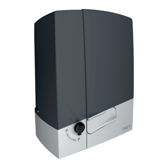
Description 801MS-0150 BXV04AGS - Operator with 24 V motor, featuring a control board with display, on-board radio decoding, movement and obstruction detecting device for gates weighing up to 400 kg that are up to 14 m long. RAL7024 grey cover. -
Page 6: Description Of Parts
Description of parts Operator Cover Control board Board-holder support Control board holder Gearmotor Housing for the RLB card Anchoring plate Housing for UR042 module Housing for two emergency batteries Housing for SMA or RGSM001 sensor Release lever Transformer Lock Mechanical limit switch Mechanical limit-switch fins Release cord hole Magnetic limit switch... - Page 7 Control board The functions on the input and output contacts, the time settings and user management are set and viewed on the display. All connections are protected by quick fuses. For the system to work properly, before fitting any plug-in card, DISCONNECT THE MAIN POWER SUPPLY and remove any batteries. Before working on the control panel, disconnect the mains power supply and remove the batteries, if any.
- Page 8 Size Usage limitations MODELS BXV04AGS BXV06AGS BXV08AGS BXV10AGS BXV04RGS BXV06RGS BXV08RGS BXV10RGS Pinion module Maximum gate-leaf length (m) Maximum gate-leaf weight (kg) 1000 1000 MODELS BXV06AGM BXV10AGM BXV04ALS BXV06ALS BXV08ALS BXV10ALS Pinion module Maximum gate-leaf length (m) Maximum gate-leaf weight (kg)
- Page 9 Technical data MODELS BXV04AGS BXV06AGS BXV08AGS BXV10AGS BXV04RGS BXV06RGS BXV08RGS BXV10RGS Power supply (V - 50/60 Hz) 230 AC 230 AC 230 AC 230 AC 110 AC 110 AC 110 AC 110 AC Motor power supply (V) 24 DC 24 DC...
-
Page 10: Installation
INSTALLATION The following illustrations are examples only. The space available for fitting the operator and accessories varies depending on the area where it is installed. It is up to the installer to find the most suitable solution. The drawings show an operator fitted on the left. Preliminary operations Dig a hole for the foundation frame. - Page 11 Insert the screws supplied in the anchoring plate. Lock the screws in place with the nuts supplied. Remove the pre-shaped clamps using a screwdriver. Fit the anchoring plate in the iron cage. The tubes must pass through the existing holes. UNI 5588 M12 Ø...
- Page 12 Remove the nuts from the screws. Insert the electrical cables into the tubes until they protrude by about 600 mm. Setting up the operator Remove the operator cover. Place the operator on top of the anchoring plate. The electrical cables must pass under the operator foundation frame Male a hole in the cable gland.
- Page 13 Fastening the rack Release the operator. Rest the rack on the pinion. Weld or fasten the rack to the gate along its entire length. To assemble the rack modules, use an extra piece and rest it under the joint, then fasten it in place using two clamps. Adjusting the pinion-rack coupling Open and close the gate manually.
- Page 14 Fastening the operator in place Only fasten the operator after adjusting the pinion-rack coupling. Fasten the operator to the anchoring plate using stoppers and nuts. Determining the travel end points with mechanical limit switches Open the gate. Insert the opening limit-switch tab in the rack. The spring must trigger the microswitch.
- Page 15 Close the gate. Insert the closing limit-switch tab in the rack. The spring must trigger the microswitch. Fasten the closing limit-switch tab using the grub screws supplied. ~ 20 Establishing the limit-switch points with magnetic limit switches * Only for BXV06AGM and BXV10AGM Magnetic limit-switch fins during closing Magnetic limit-switch fins during opening Open the gate.
- Page 16 Fasten the support to the rack using the grub screws supplied. The limit-switch fin magnet must be perpendicular to the magnetic sensor. Fasten the limit-switch fin using the screw (supplied). Close the gate. Insert the magnetic closing limit-switch fin on the rack. The fin magnet must be between 10 and 30 mm from the magnetic sensor.
-
Page 17: Electrical Connections
ELECTRICAL CONNECTIONS Passing the electrical cables Connect all wires and cables in compliance with the law. The electrical cables must not touch any parts that may overheat during use (such as the motor and transformer). Use cable glands to connect the devices to the control panel. One of these must be used exclusively for the power supply cable. Power supply Make sure the mains power supply is disconnected during all installation procedures. -
Page 18: Signalling Devices
Signalling devices Additional light It increases the light in the manoeuvring area. Flashing beacon It flashes when the operator opens and closes. Operator status warning light It notifies the user of the operator status. 10 11 E... -
Page 19: Command And Control Devices
Command and control devices Antenna with RG58 cable STOP button (NC contact) It stops the gate and excludes automatic closing. Use a control device to resume movement. If the contact is not used, it must be deactivated during programming. Control device (NO contact) OPEN ONLY or PARTIAL OPENING function Fully or partially open the gate. - Page 20 DIR / DELTA-S photocells DIR / DELTA-S photocells Standard connection Connection with safety test See function F5, safety devices test. 3P 7 3P 7 10 TS 2 CX CY FA F F 10 TS 2 CX CY FA F F 2 TX C NC TX 2 2 TX C NC...
-
Page 21: Getting Started
PROGRAMMING Programming button functions ESC button The ESC button is used to perform the operations described below. Exit the menu Delete the changes Go back to the previous screen Stop the operator < > buttons The <> buttons are used to perform the operations described below. Navigate the menu Increase or decrease values Open or close the operator... - Page 22 Safety devices test Check that the photocells connected to the inputs are operating correctly, after each opening and closing command. Safety devices test 0 =Deactivated (Default) 1 = CX 2 = CY 4 = CX+CY Hold-to-run With the function active, the operator stops moving (opening or closing) when the control device is released. When the function is active, it excludes all other control devices.
- Page 23 Soft start Set a slowdown of a few seconds after each opening and closing command. Soft start OFF (Default) Sensor type Set the type of control device. Sensor type 0 = Transponder selector switch 1 = Keypad selector (default) Additional light Choose the operating mode of the lighting device connected to the output.
- Page 24 Travel sensitivity Adjust the obstruction detection sensitivity during boom travel. Travel sensitivity 10% to 100% (Default 100%) - 10% = maximum sensitivity - 100% = minimum sensitivity Slowdown sensitivity Adjust the obstacle-detection sensitivity level during slowdown. This function appears only if the [Encoder] function is active. Slowdown sensitivity 10% to 100% (Default 100%) - 10% = maximum sensitivity - 100% = minimum sensitivity...
- Page 25 Transferring MASTER-SLAVE parameters Enable sharing for the parameters programmed on the master gate with the slave gate. This function appears only if the [RSE] function is active. Transferring MASTER-SLAVE OFF (Default) parameters Opening direction Set the gate opening direction. Opening direction 0 = To the left (default) 1 = To the right CRP address...
- Page 26 The operation can be carried out by using a transmitter or another control device. The boards that manage the control devices (AF - R700 - R800) must be inserted into the connectors. Download the LIST OF REGISTERED USERS form from the docs.came.com portal by typing in L20180423. New user...
- Page 27 Remove all Remove all registered users. Remove all OFF (Default) Radio decoding Choose the type of radio coding for the transmitters enabled to control the operator. If you choose the type of radio coding for the transmitters [Rolling code] or [TW key block], any transmitters with a different type of radio coding saved previously will be deleted.
-
Page 28: Import/Export Data
Import/export data Save user data and system configuration data on a MEMORY ROLL card. The stored data can be reused for another control board to configure another system in the same way. Before inserting and removing the MEMORY ROLL card, DISCONNECT THE MAINS POWER SUPPLY TO THE LINE. Insert the MEMORY ROLL card into the corresponding connector on the control board. -
Page 29: Error Messages
ERROR MESSAGES Calibration error Adjustment error Encoder failure error Service test failure error Operating time error Obstacle detected during closing Obstacle detected during opening The maximum number of obstacles detected consecutively has been exceeded The limit switches are both open Serial communication error Incompatible transmitter error Wireless system communication error... - Page 30 PAIRED OPERATION Two connected operators are controlled with one command. Electrical connections Connect the two electronic boards with a UTP CAT 5 cable. Insert an RSE card into both control boards. Connect up the electrics for the devices and accessories. The devices and accessories must be connected to the control board which will be set as the MASTER.
- Page 31 MCBF Models BXV04 BXV06 BXV08 BXV10 14 m - 400 kg 150000 18 m - 600 kg 150000 20 m - 800 kg 150000 20 m - 1000 kg 150000 Installation in windy area -15% -15% -15% -15% The percentages indicate how much the number of cycles should be reduced in relation to the type and number of accessories installed. Before carrying out any cleaning or maintenance, or replacing any parts, disconnect the device from the power supply.
- Page 32 CAME S.p.A. Via Martiri della Libertà, 15 31030 Dosson di Casier Treviso - Italy Tel. (+39) 0422 4940 Fax (+39) 0422 4941...
Need help?
Do you have a question about the BXV04AGS and is the answer not in the manual?
Questions and answers