
Related Manuals for CAME BX241


Summary of Contents for CAME BX241
- Page 1 AUTOMATION SYSTEM FOR SLIDING GATES BX241 INSTALLATION MANUAL...
- Page 2 4 Description 4.1 Gearmotor The BX-241 ratiomotor is designed and built by CAME CANCELLI AUTOMATICI S.p.A. and it meets the safety standards in force. Guaranteed 24 months if not tampered with. The casing is made up of a fused aluminium part where the irreversible electromechanical ratiomotor is housed and an ABS plastic- lined part that encloses the electronic board, the battery charger board and the bracket to house the two emergency batteries.
-
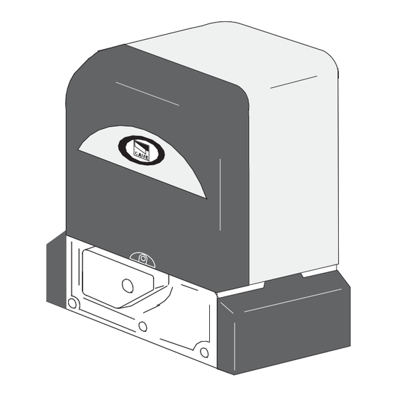
Page 3: Parts Description
4.3 Parts description GEARMOTOR UNIT 1 - Ratiomotor 2 - Board cover support 3 - End-stop flaps 4 - ZBX241 basic control board 5 - BN1 battery charger board 6 - Electric board front cover 7 - Release door 8 - Base plate 9 - Securing screws 10 - Plates for securing screws 11 - Nuts... -
Page 4: Installation
5 Installation Installation must be carried out by expert qualified personnel and in full observance of regulations in force. 5.1 Preliminary checks Before proceeding with the installation, it is necessary to: • Make sure the door is rigid and compact and that the sliding wheels are well oiled and in good condition. •... - Page 5 1- BX-241 unit 6- Key-operated selector switch 2- Control board incorporated 7- Flashing light indicating door movement 3- Radio receiver 8- Antenna 4- Limit-switch tabs 9- Safety photocells 5- Rack 10- Photocell column 11- Closure stop 5.4 Motor to base anchorage The following applications are only examples, as the space required for unit installation and the accessories vary de- pending on dimensions and therefore it is up to the installer to select the best solution.
-
Page 6: Unit Installation
5.5 Unit installation During the initial phase of installation, the feet should protrude by 5-10 mm. in order to allow for alignment, anchorage of the rack and further adjustments. Perfect alignment with the guide rail is made possible by the (paten-ted) built-in regulation system, which consists of: - slots for horizontal adjustment;... - Page 7 5.7 Attaching the switch tabs Position the limit-switch tabs (whose positions determine the limits of gate travel) on the rack. Note: do not allow the gate to strike the mechanical stops in the open or closed positions. C A M E 5.8 Gear release To open the access door, insert the key, push down and rotate clockwise.
-
Page 8: Control Board
6 Control board 6.1 Technical description board ZBX241 This control board is powered by 230V a.c. across terminals L1 and L2, and is protected by a 1A fuse on the main power line. Control systems are powered by low voltage and protected with by a 1.6A fuse. The total power consumption of 24V accessories must not exceed 40 W. - Page 9 6.3 Description board BN1 The BN1 board allows the automation to be battery operated in case of a power outage. When power is restored, the card also recharges the batteries. 1 - ZBX241 board connecting terminal board 2 - The green LED indicator light signals mains power supply on 3 - The red LED indicator light signals emergency battery power supply on 6.4 Emergency battery connection Insert batteries in the appropriate bracket (Fig.1) and connect them (using the cables provided) to the ZBX241 board (Fig.2)
-
Page 10: Electrical Connections
6.6 Electrical connections 10 10 11 11 E1 E1 1 1 3P C1 C1 C3 C3 7 7 230V (a.c.) power supply 24V(d.c.) motor 24V output in motion (e.g. fl ashing light 25W) 24V powering accessories max. 40W Pushbutton stop (N.C.) Pushbutton open (N.O.) Pushbutton partial opening (N.O.) Contact radio and/or pushbutton for controlled (see dip-switch 2-3) -
Page 11: Function Selections
6.7 Function selections 1 ON - Automatic closure enabled 2 ON - "Open-stop-close-stop" radio control and/or button function enabled (with plug-in radiofrequency board) 2 OFF - "Open-close-reverse" radio control and/or button function enabled (with plug-in radiofrequency board) 3 ON - "Only open" radio control and/or button function enabled (with plug-in radiofrequency board) 4 ON - "Maintained action"... - Page 12 7.2 Procedure for codifying the transmitter TOP QUARTZ SERIES Standard encoding procedure T262M - T264M - T2622M - T302M - T304M - T3022M 1 assign a code (also on file) 2 connect encoding jumper J Press P1 or P2 in sequence in order to register the code;...
- Page 13 T2622M - T3022M T264M - T304M 1° Code P1 = CH1 P1 = CH1 P2 = CH2 P2 = CH2 P3 = CH3 P4 = CH4 2° Code P3 = CH1 P4 = CH2 TOP SERIES T432M - T312M set the code to dip-switch C and channel to D (P1=CH1 and P2=CH2, default setting) T434M - T314M T432S - T432SA - T434MA - T432NA - T434NA set code only...
- Page 14 ATOMO SERIES AT01 - AT02 - AT04 see instruction sheet inside the pack of AF43SR circuit card TOUCH SERIES TCH 4024 - TCH 4048 see instructions on pack 10 11 E1 1 3P C1 C3 7 7.3 Memorizing the code on the command board Flashing LED 1) Keep the "CH1"...
-
Page 15: Maintenance
UNI EN ISO 14001 standard to ensure environmental protection. Please continue our efforts to protect the environment—which CAME considers one of the cardinal elements in the development of its operational and market strategies—simply by observing brief recommendations as regards disposal: DISPOSAL OF PACKAGING –... - Page 16 CAME UNITED KINGDOM LTD UNIT 3, ORCHARD BUSINESS PARK TOWN STREET, SANDIACRE NOTTINGHAM - NG10 5BP - U.K. Tel 0044 115 9210430 Fax 0044 115 9210431...
Need help?
Do you have a question about the BX241 and is the answer not in the manual?
Questions and answers