Advertisement
Table of Contents
- 1 Parts List
- 2 Tools and Supplies Required
- 3 Remote Control Engine Starter Installed on the Vehicle
- 4 Installation
- 5 Removing the Vehicle Parts
- 6 Installing the Antenna
- 7 Routing the Engine Starter Harness
- 8 Reinstalling the Left A-Pillar Trim
- 9 Setting the Automatic Defrost Function
- 10 Remote Engine Starter Registration
- 11 Function Check
- Download this manual
INSTRUCTIONS
PARTS LIST
Remote Engine Starter Unit Kit
P/N 08E91-E22-101B
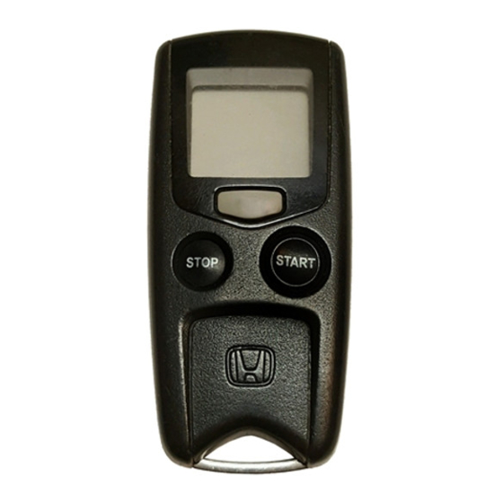
Transmitter
Control unit
Antenna
Key ring
Protective tape
Fuse label
Caution label
© 2010 American Honda Motor Co., Inc. – All Rights Reserved.
Accessory
REMOTE CONTROL ENGINE
STARTER
AII 44367 (1008)
Application
2011 CR-V
Accessory User's Information Manual
Quick Start Guide
Remote Control Engine Starter Attachment Kit
(With vehicle security)
P/N 08E92-SWA-100B
Engine starter harness
Control unit bracket
Template
Bracket
3
Relays
Publications No.
AII 44637
Issue Date
AUG 2010
1 of 28
08E92-SWA-1B00-91
Advertisement
Table of Contents

Related Manuals for Honda 08E91-E22-101B


Summary of Contents for Honda 08E91-E22-101B
- Page 1 (With vehicle security) P/N 08E92-SWA-100B Engine starter harness Antenna Control unit bracket Key ring Template Protective tape Fuse label Bracket Caution label Relays 1 of 28 © 2010 American Honda Motor Co., Inc. – All Rights Reserved. AII 44367 (1008) 08E92-SWA-1B00-91...
- Page 2 Self-tapping screws, 5 x 12 mm Remote Control Engine Starter Attachment Kit 26 Wire ties (Without vehicle security) P/N 08E92-SWA-100C Engine starter harness Wire ties with clip 2 of 28 AII 44367 (1008) © 2010 American Honda Motor Co., Inc. – All Rights Reserved.
- Page 3 HDS (Honda Diagnostic System) Fender cover Needle nose pliers Tape 6 mm Flange nut 10 mm Combination wrench Self-tapping screws, 5 x 12 mm Spacers 3 of 28 © 2010 American Honda Motor Co., Inc. – All Rights Reserved. AII 44367 (1008)
- Page 4 CONTROL UNIT (3A) Without vehicle security ENGINE ANTENNA STARTER FUSE HARNESS (40A, 40A) FUSE (3A) HOOD LOCK 921303AD HOOD SWITCH CONTROL UNIT HARNESS 4 of 28 AII 44367 (1008) © 2010 American Honda Motor Co., Inc. – All Rights Reserved.
- Page 5 Using a small flat-tip screwdriver, adjust the switches on the control unit as shown. 5 of 28 © 2010 American Honda Motor Co., Inc. – All Rights Reserved. AII 44367 (1008)
- Page 6 Make sure to tap perpendicular to the A-pillar trim. Push. RIGHT SUN VISOR HOLDER Turn. 2 SUN VISOR HOLDERS SHOP TOWEL FLAT-TIP 812414AB SCREWDRIVER 6 of 28 AII 44367 (1008) © 2010 American Honda Motor Co., Inc. – All Rights Reserved.
- Page 7 (one pin and one clip). 3 CLIPS KNOB Turn. LEFT FRONT SIDE STEP TRIM ’ DRIVER S UNDER 6303090B COVER CLIP 6303080B 7 of 28 © 2010 American Honda Motor Co., Inc. – All Rights Reserved. AII 44367 (1008)
- Page 8 COLUMN LOWER COVER 3 RETAINING TABS RETAINING TILT LEVER GUIDE FLAT-TIP SCREWDRIVER 7215010K 20. Remove the steering column upper cover (three retaining tabs). 8 of 28 AII 44367 (1008) © 2010 American Honda Motor Co., Inc. – All Rights Reserved.
- Page 9 EDGE OF BLACK CERAMIC PAINT Align these SCALE edges with the edges of the PLATE black ceramic paint. WINDSHIELD TAPE TEMPLATE 932001AD 972302AD 9 of 28 © 2010 American Honda Motor Co., Inc. – All Rights Reserved. AII 44367 (1008)
- Page 10 HEADLINER 60 mm (2.4 in.) Cut. 15 mm (0.6 in.) ANTENNA URETHANE CABLE TAPE Align. ANTENNA PLATE 932003AD ANTENNA 780101BK 10 of 28 AII 44367 (1008) © 2010 American Honda Motor Co., Inc. – All Rights Reserved.
- Page 11 36. Route the antenna cable down under the dashboard. Tuck the antenna cable between the left A-pillar and VEHICLE URETHANE PANEL TAPE the dashboard, then reinstall the weatherstrip. 932005AD 11 of 28 © 2010 American Honda Motor Co., Inc. – All Rights Reserved. AII 44367 (1008)
- Page 12 40. Plug the three relays into the relay block of the 44. Secure the vehicle 4-pin connector and 2-pin engine starter harness. connector to the vehicle harness using a wire tie. 12 of 28 AII 44367 (1008) © 2010 American Honda Motor Co., Inc. – All Rights Reserved.
- Page 13 ANTENNA CABLE 921602BD 48. Remove the vehicle ground bolt from the vehicle. Secure the engine starter harness ground terminal with the vehicle ground bolt. 13 of 28 © 2010 American Honda Motor Co., Inc. – All Rights Reserved. AII 44367 (1008)
- Page 14 921608BD 58. Secure the engine starter harness 23-pin connector (blue), and the engine starter harness to the vehicle harness with three wire ties. 14 of 28 AII 44367 (1008) © 2010 American Honda Motor Co., Inc. – All Rights Reserved.
- Page 15 ENGINE STARTER HARNESS 7-PIN CONNECTORS INSTRUMENT PANEL ENGINE STARTER HARNESS VEHICLE HARNESS 6 x 12 mm 6D01120Y 6 mm FLANGE WASHER BRACKET BOLT 921610BD 15 of 28 © 2010 American Honda Motor Co., Inc. – All Rights Reserved. AII 44367 (1008)
- Page 16 7-pin connector into the engine starter harness 7-pin connector. IGNITION ENGINE STARTER SWITCH HARNESS 7-PIN CONNECTOR VEHICLE 7-PIN (white) CONNECTOR WIPER (White) SWITCH 6D01160Y ENGINE STARTER HARNESS 7213020K 16 of 28 AII 44367 (1008) © 2010 American Honda Motor Co., Inc. – All Rights Reserved.
- Page 17 SHAFT WIRE TIE HARNESS 921703BD 921701BD 76. Secure the engine starter harness and antenna cable to the vehicle harness with one wire tie. 17 of 28 © 2010 American Honda Motor Co., Inc. – All Rights Reserved. AII 44367 (1008)
- Page 18 STEERING COLUMN LOWER COVER DRIVER’S UNDER 921705AD COVER 752201AK 82. Attach a urethane tape to the bracket on the steering column lower cover. 18 of 28 AII 44367 (1008) © 2010 American Honda Motor Co., Inc. – All Rights Reserved.
- Page 19 85. Remove two old spacers from the left fender arch. 86. Using isopropyl alcohol, thoroughly clean the area where the spacers will attach. Replace the two spacers with new ones. 19 of 28 © 2010 American Honda Motor Co., Inc. – All Rights Reserved. AII 44367 (1008)
- Page 20 HOOD HARNESS LOCK OPENER CABLE HOOD LOCK ENGINE COMPARTMENT 6311090Y 6831010Y 92. Attach the hood lock opener cable to the new hood lock. 20 of 28 AII 44367 (1008) © 2010 American Honda Motor Co., Inc. – All Rights Reserved.
- Page 21 2-pin connector into the interior compartment. FRONT HOOD LOCK 2-PIN HOOD CONNECTOR SWITCH HARNESS GROMMET VEHICLE PANEL 6311150Y INSIDE OUTSIDE VEHICLE Install the grommet. GROMMET 6311113Y (Discard.) 21 of 28 © 2010 American Honda Motor Co., Inc. – All Rights Reserved. AII 44367 (1008)
- Page 22 HOOD ADHESIVE BACKING CAUTION LABEL 6D2401AK 104. Attach the caution label to the hood. 22 of 28 AII 44367 (1008) © 2010 American Honda Motor Co., Inc. – All Rights Reserved.
- Page 23 Do not push the left A-pillar trim excessively. LEFT CLIP A-PILLAR VEHICLE PANEL CLIP AREA MARKED “SIDE CURTAIN AIRBAG” LEFT A-PILLAR TRIM 6519020Y 23 of 28 © 2010 American Honda Motor Co., Inc. – All Rights Reserved. AII 44367 (1008)
- Page 24 (indicating current setting) REAR RECIRCU- IGNITION DEFOGGER LATION switch switch switch 10 Seconds after turning the ignition switch to ON (II) 5419160K 5718220S 24 of 28 AII 44367 (1008) © 2010 American Honda Motor Co., Inc. – All Rights Reserved.
- Page 25 Input the VIN and other information, then click the check button. Select CHECK BUTTON “R/C ENG STARTER” 752504AS Input the VIN and CHECK BUTTON other information. 752502AS 25 of 28 © 2010 American Honda Motor Co., Inc. – All Rights Reserved. AII 44367 (1008)
- Page 26 The date of the HDS tester should also be the same. Input the PCM Code. Select CHECK BUTTON “REGISTER REMOTE CONTROL ENGINE STARTER UNIT.” 752506AS CHECK BUTTON 752509AS 26 of 28 AII 44367 (1008) © 2010 American Honda Motor Co., Inc. – All Rights Reserved.
- Page 27 Check that “Check that the engine can be started by the Transmitter” is shown. CHECK BUTTON 752511AS 13. Perform the function test on the next page, then remove the HDS. 27 of 28 © 2010 American Honda Motor Co., Inc. – All Rights Reserved. AII 44367 (1008)
- Page 28 Check the operation of the transmitter when the vehicle is 100 m to 150 m (325 to 490 ft.) away, and in direct sight. 28 of 28 AII 44367 (1008) © 2010 American Honda Motor Co., Inc. – All Rights Reserved.
Need help?
Do you have a question about the 08E91-E22-101B and is the answer not in the manual?
Questions and answers