Honda 08E91-E22-101A Installation Instructions Manual
Remote control engine starter
Hide thumbs
Also See for 08E91-E22-101A:
- Installation instructions manual (23 pages) ,
- Installation instructions manual (21 pages) ,
- Installation instructions manual (23 pages)
Advertisement
Quick Links
INSTALLATION
INSTRUCTIONS
PARTS LIST
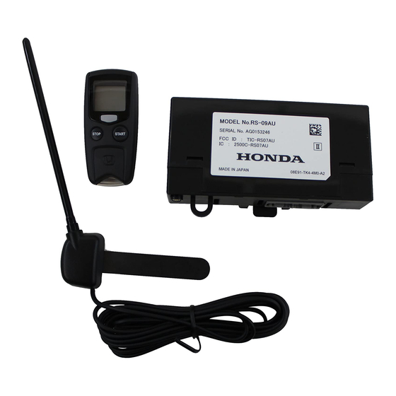
Remote Control Engine Starter Unit Kit
P/N 08E91-E22-101A
Transmitter
Control unit
Antenna
Key ring
Protective tape
Fuse label
Caution label
© 2013 American Honda Motor Co., Inc. – All Rights Reserved.
Accessory
REMOTE CONTROL ENGINE
STARTER
AII 13148-49239 (1302)
Application
2013 CR-V
(EXCEPT LX)
Accessory User's Information Manual
Quick Start Guide
Remote Control Engine Starter Attachment Kit
P/N 08E92-T0A-100A
Control unit bracket
Engine starter harness
3
Relays
8 mm Nut
20 Wire ties
Publications No.
AII 13148-49239
Issue Date
FEB 2013
1 of 27
08E92-T0A-1A00-90
Advertisement

Related Manuals for Honda 08E91-E22-101A


Summary of Contents for Honda 08E91-E22-101A
- Page 1 Control unit bracket Antenna Engine starter harness Key ring Relays Protective tape Fuse label 8 mm Nut 20 Wire ties Caution label 1 of 27 © 2013 American Honda Motor Co., Inc. – All Rights Reserved. AII 13148-49239 (1302) 08E92-T0A-1A00-90...
-
Page 2: Installation
Equipment Program. On the iN click on: Service > Service Bay > Tool and Equipment Program, the enter the number under search. Or call 888-424-6857. Trim Tool Set (T/N SOJATP2014) 2 of 27 AII 13148-49239 (1302) © 2013 American Honda Motor Co., Inc. – All Rights Reserved. - Page 3 SW:5 Trunk Main SW------------------------> OFF SUNGLASS HOLDER RIGHT SW:6 Reserve ---------------------------------> OFF Open. LENS 4 SCREWS 921301AD LEFT LENS 4 RETAINING TABS 4 RETAINING Q0N2012AG TABS 3 of 27 © 2013 American Honda Motor Co., Inc. – All Rights Reserved. AII 13148-49239 (1302)
- Page 4 A-PILLAR TRIM Remove. VEHICLE CLIP PANEL DRIVER’S A-PILLAR TRIM DRIVER’S A-PILLAR TRIM DRIVER’S DOOR OPENING Q0N2016AG SEAL Pull away. 2 CLIPS DRIVER’S A-PILLAR Q0N2014AG 4 of 27 AII 13148-49239 (1302) © 2013 American Honda Motor Co., Inc. – All Rights Reserved.
- Page 5 Remove the driver’s A-pillar trim. Install the new clip DRIVER’S AIR OUTLET (supplied) to the driver’s A-pillar trim. NEW CLIP DRIVER’S A-PILLAR TRIM (inside) RETAINING SELF-TAPPING SCREW CLIP Q0N2020BG Q0N2018AG 5 of 27 © 2013 American Honda Motor Co., Inc. – All Rights Reserved. AII 13148-49239 (1302)
- Page 6 DRIVER’S DASHBOARD LOWER COVER LOCK 8 CLIPS Q0N2022AG PLASTIC TRIM TOOL Q0N2024BG 19. Using a plastic trim tool, release the lock as shown. 6 of 27 AII 13148-49239 (1302) © 2013 American Honda Motor Co., Inc. – All Rights Reserved.
- Page 7 21. Secure the upper column cover to the meter panel with the tape. 2 RETAINING METER PANEL TABS TAPE LOWER COLUMN COVER SELF-TAPPING SCREW Q0N2028AG UPPER COLUMN COVER Q0N2026AG 7 of 27 © 2013 American Honda Motor Co., Inc. – All Rights Reserved. AII 13148-49239 (1302)
- Page 8 (two clips). DRIVER’S DOOR OPENING SEAL NEEDLE Pull away. NOSE PLIERS 2 CLIPS SCALE DRIVER’S KICK ANTENNA PLATE PANEL Q0N2030AG Q0N1708CG 8 of 27 AII 13148-49239 (1302) © 2013 American Honda Motor Co., Inc. – All Rights Reserved.
- Page 9 Press the antenna firmly for 30 seconds. 32. Remove the template. 9 of 27 © 2013 American Honda Motor Co., Inc. – All Rights Reserved. AII 13148-49239 (1302)
- Page 10 CABLE the antenna cable to the vehicle panel with two cut pieces of urethane tape. Be careful not to crease the headliner. Q0N1709BG 10 of 27 AII 13148-49239 (1302) © 2013 American Honda Motor Co., Inc. – All Rights Reserved.
- Page 11 VEHICLE TOP VIEW 28-PIN CONNECTOR Q0N1805BG 46. Plug the vehicle 28-pin connector into the engine starter harness 28-pin connector. Q0N1802BG ENGINE STARTER HARNESS 11 of 27 © 2013 American Honda Motor Co., Inc. – All Rights Reserved. AII 13148-49239 (1302)
- Page 12 NOTE: Check that the engine starter harness 5-pin connector is securely connected to the fuse box 5-pin connector. A loose connection can cause the engine to stall. 12 of 27 AII 13148-49239 (1302) © 2013 American Honda Motor Co., Inc. – All Rights Reserved.
- Page 13 52. Slide the other clip on the engine starter harness onto the vehicle connector. Note the direction and the orientation of the clip. ENGINE STARTER HARNESS Q0N1903BG VEHICLE FRONT CONNECTOR CLIP Q0N1902BG 13 of 27 © 2013 American Honda Motor Co., Inc. – All Rights Reserved. AII 13148-49239 (1302)
- Page 14 38-PIN CONNECTOR HARNESS SIDE VIEW 8-PIN VEHICLE 38-PIN CONNECTOR CONNECTOR QA21701AG 59. Remove the 8-pin connector from the vehicle 38-pin connector (two tabs). 14 of 27 AII 13148-49239 (1302) © 2013 American Honda Motor Co., Inc. – All Rights Reserved.
- Page 15 VEHICLE HARNESS ENGINE STARTER HARNESS ELECTRICAL Q0N1907AG TAPE 63. Reinstall the connector cover. 64. Plug the vehicle 38-pin connector into the fuse box. 15 of 27 © 2013 American Honda Motor Co., Inc. – All Rights Reserved. AII 13148-49239 (1302)
- Page 16 69. Secure the engine starter harness to the hole in the left knee bolster using the clip on the engine starter harness as shown. 16 of 27 AII 13148-49239 (1302) © 2013 American Honda Motor Co., Inc. – All Rights Reserved.
- Page 17 72. Align the white tape on the engine starter harness with the vehicle clip, and secure the engine starter harness to the vehicle harness with two wire ties as shown. 17 of 27 © 2013 American Honda Motor Co., Inc. – All Rights Reserved. AII 13148-49239 (1302)
- Page 18 10-pin connector. 78. Plug the remaining engine starter harness 10-pin connector into the wiper switch. 18 of 27 AII 13148-49239 (1302) © 2013 American Honda Motor Co., Inc. – All Rights Reserved.
- Page 19 12-PIN CONNECTOR QA20704BG 81. Plug the remaining engine starter harness 12-pin RIGHT connector into the combination light switch. CONNECTOR CORD (without undue strain) Q0N2010BG 19 of 27 © 2013 American Honda Motor Co., Inc. – All Rights Reserved. AII 13148-49239 (1302)
- Page 20 85. Loosely secure the antenna cable to the dashboard with one wire tie loosely installed in step 70. CONTROL UNIT ANTENNA CABLE ENGINE STARTER HARNESS 28-PIN Q0N2306AG CONNECTOR 20 of 27 AII 13148-49239 (1302) © 2013 American Honda Motor Co., Inc. – All Rights Reserved.
- Page 21 Reinstall the vehicle flange nut. Install the 8 mm nut (supplied) on top of HOLE the vehicle flange nut. ENGINE STARTER HARNESS CLIP Q0N2308BG 21 of 27 © 2013 American Honda Motor Co., Inc. – All Rights Reserved. AII 13148-49239 (1302)
- Page 22 85. ANTENNA CABLE Bundle up the excess. DASHBOARD WIRE TIE Q0N2311BG 22 of 27 AII 13148-49239 (1302) © 2013 American Honda Motor Co., Inc. – All Rights Reserved.
-
Page 23: Remote Engine Starter Registration
107. Proceed to the REMOTE ENGINE STARTER REGISTRATION (Page 23) and FUNCTION CHECK (Page 26). Input the VIN and other CHECK BUTTON required information. 752502AS 23 of 27 © 2013 American Honda Motor Co., Inc. – All Rights Reserved. AII 13148-49239 (1302) - Page 24 STARTER UNIT, then click the check button. Select CHECK BUTTON “R/C ENG STARTER.” Select CHECK BUTTON “REGISTER REMOTE 752504AS CONTROL ENGINE STARTER UNIT.” 752506AS 24 of 27 AII 13148-49239 (1302) © 2013 American Honda Motor Co., Inc. – All Rights Reserved.
- Page 25 Input the PCM Code. CHECK BUTTON 752511AS 13. Perform the function test on page 26, then CHECK BUTTON disconnect the HDS. 752509AS 25 of 27 © 2013 American Honda Motor Co., Inc. – All Rights Reserved. AII 13148-49239 (1302)
-
Page 26: Function Check
Check the operation of the transmitter when the vehicle is 100 m to 150 m (325 to 490 ft.) away and in direct sight. Insert the key in the ignition and start the engine, check the operation of the headlights and wipers. 26 of 27 AII 13148-49239 (1302) © 2013 American Honda Motor Co., Inc. – All Rights Reserved. - Page 27 Press and release the Stop button. 10. Perform the function check on both transmitters. NOTE: Only 2 remotes can be stored in the system’s memory. 27 of 27 © 2013 American Honda Motor Co., Inc. – All Rights Reserved. AII 13148-49239 (1302)
Need help?
Do you have a question about the 08E91-E22-101A and is the answer not in the manual?
Questions and answers