Table of Contents
Advertisement
Quick Links
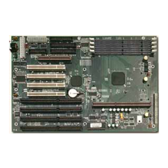
Tyan S1830
Tsunami AT
Motherboard User's Manual
Revision 1.20
Copyright © Tyan Computer Corporation, 1998. All rights reserved. No part of this
manual may be reproduced or translated without prior written consent from Tyan
Computer Corp.
All registered and unregistered trademarks and company names contained in this
manual are propery of their respective companies including, but not limited to the
following.
AMIBIOS is a trademark of American Megatrends Incorporated.
Windows is a trademark of Microsoft Corporation.
IBM, PC, AT, PS/2 are trademarks of IBM Corporation.
INTEL, Pentium II, Celeron are trademarks of Intel Corporation.
S1830S/SL Tsunami AT is a trademark of TYAN Computer Corporation.
Information contained in this publication has been carefully checked for accuracy and
reliability. In no event will Tyan Computer be held liable for any direct or indirect,
incidental or consequential damage, loss of use, loss of data, or other malady resulting
from errors or inaccuracies of information contained in this manual. The information
contained in this document is subject to change without notice.
PRINTED IN USA
Advertisement
Table of Contents

Related Manuals for TYAN S1830


Summary of Contents for TYAN S1830
- Page 1 Information contained in this publication has been carefully checked for accuracy and reliability. In no event will Tyan Computer be held liable for any direct or indirect, incidental or consequential damage, loss of use, loss of data, or other malady resulting from errors or inaccuracies of information contained in this manual.
-
Page 2: Table Of Contents
Table of Contents 1. Introduction....................4 Overview....................4 Icons....................5 Hardware Specifications/Features........... 5 Software Specifications..............7 Technical Support................8 Returning Merchandise for Service..........8 2. Board Installation..................10 Unpacking................... 10 Installation..................10 Setting Jumpers.................. 23 3. Onboard Resource Settings................ 24 Quick Reference for Jumpers............ - Page 3 Displayed Error Messages............... 64 Glossary....................66...
-
Page 4: Introduction
Introduction Introduction Overview The S1830S and S1830SL (S1830) Tsunami AT is a quality, high performance mainboard designed for Intel Pentium II and Celeron microprocessors. This mainboard utilizes the Intel 440BX AGPset and can support CPU speeds of 233MHz through 450MHz, and host bus speeds of 66MHz or 100MHz. The Tsunami AT also has 100MHz Front Side Bus support, which allows you to take full advantage of 100MHz SDRAM memory modules. -
Page 5: Icons
Remember to take a look at TYAN Computer’s web site located at http://www.tyan.com. There you can find information on all of TYAN’s products along with FAQs, distributors list, drivers, and BIOS setting explana- tions. Icons In order to help you navigate this manual and set up your system, we have added several icons to our format. - Page 6 •One 32-bit AGP slot •Four 32-bit PCI Bus Master slots •Four 16-bit ISA slots •One shared, eight usable Physical Dimensions •Baby AT design. •13 inches x 8.6 inches BIOS Information •AMI Plug and Play flash BIOS •Deep Green, Energy Star, Year 2000 http://www.tyan.com...
-
Page 7: Software Specifications
NT, OS/2, Novell Netware, Solaris, and SCO Unix. Information presented in this publication has been carefully checked for reliability. However, no responsibility is assumed for inaccuracies. The information contained in this document is subject to change without notice. S1830 Tsunami AT... -
Page 8: Technical Support
Return Merchandise Authorization (RMA) number. The RMA number should be prominently displayed on the outside of the shipping carton and the package should be mailed prepaid, or hand-carried to the manufacturer. TYAN will pay to have the board shipped back to you. http://www.tyan.com... - Page 9 This page has been intentionally left blank. S1830 Tsunami AT...
-
Page 10: Board Installation
You are now ready to install your mainboard. The mounting hole pattern of the S1830 matches the Baby AT system board specifications. Your chassis should be that of a standard AT mainboard form factor with AT or ATX power supply. - Page 11 Install the motherboard into your case. Follow the instructions provided by the case manufacturer for proper installa- tion guidelines. TYAN recommends that you use only one screw to hold down the motherboard. The rest of the mounting holes should be used for the plastic standoffs.
- Page 12 After connecting the power, make sure the connector is seated firmly into its socket so it will not become loose or fall off when the computer is jostled or moved. Note: Tyan recommends using an ATX power impor- tant! supply that conforms to industry standard revision 2.01.
- Page 13 In most cases, this is the proper way of connecting your IDE cable to the hard drive. Figure 5 (on the next page) shows the IDE cable properly connected to the motherboard. Figure 4 S1830 Tsunami AT...
- Page 14 Refer to Figure 6 for a detailed anatomy of the floppy cable. Remember, you can only have 2 floppy drives connected at any given time. important! http://www.tyan.com...
- Page 15 Light on the floppy is on constantly: a dead give-away that the cable is on backwards. Reverse the cable at the motherboard end or the floppy end and try again. Next are the Com and Printer ports. Figure 7 S1830 Tsunami AT...
- Page 16 On most TYAN cables, there should be a pin missing on the motherboard. This is normal since it lines up with a key pin on the I/O connectors.
- Page 17 Because of this, your memory may not work correctly in a TYAN board though it may work well in a competitor’s board. This is because many of our competitors do not adhere to the strict tolerances required for high performance.
- Page 18 Place the DIMMs in an anti-static bag as soon as you remove them to avoid static damage. Finally, install your CPU. Pentium II processors (233 through 400MHz) can be used on the Tsunami AT. Please refer to pages 27-29 for the correct CPU jumper settings for your board. http://www.tyan.com...
- Page 19 Installation of a Pentium II processor requires a CPU retention module, which is first secured onto the motherboard. To attach the retention module, place the motherboard on a flat surface. Locate the key pin on one end of the Pentium II slot on the board. Then carefully line S1830 Tsunami AT...
- Page 20 Locate the cooling fan connector (e.g. FAN1) on the motherboard. Plug the CPU’s cooling fan cable into the cooling fan connector on the board. There will be a plastic clip assembly similar to that of the ATX power connector that will http://www.tyan.com...
- Page 21 Notice that the bottom two pins are of different sizes. The size of the pins and the holes in the motherboard will determine the correct orientation. When the bracket is correctly installed, the four pins on top will be S1830 Tsunami AT...
- Page 22 Lock the heat sink mount to the board by inserting the two mounting locks (Figure 20) into the pins of the heat sink mounting bracket which are now below the mainboard. There will be a click when the locks are securely fastened. Figure 20 http://www.tyan.com...
-
Page 23: Setting Jumpers
The metal rod inside the plastic shell bridges the gap between the two pins, completing the circuit. See the drawings below for examples of “on” and “off” pins and jumpers. 3 (or more) pin jumpers 2 pin jumpers open S1830 Tsunami AT... -
Page 24: Onboard Resource Settings
The tables on the following pages will help you set the jumpers for CPU speed, InfraRed, and external connector pin assignments, among others. The miniature motherboard maps will help you locate the jumpers on your board. A full-page map of the motherboard can be found on the facing page. http://www.tyan.com... -
Page 25: Map Of Motherboard Jumpers
ONBOARD JP14 ATX power connector DIMM bank 4 DIMM bank 3 FAN1 COM1 COM2 DIMM bank 2 DIMM bank 1 AGP port PCI slot 1 PCI slot 2 PCI slot 3 CON2 CON3 PCI slot 4 ISA slot 1 CPU slot (Slot One type) ISA slot 2 ISA slot 3 AMIBIOS... - Page 26 Chapter 3 Onboard Resource Settings PS/2 Mouse Connector AT Keyboard port 4 PCI slots AGP port 4 ISA slots 4 DIMM slots One SEC slot (Slot One type) http://www.tyan.com...
-
Page 27: Cmos Reset
CPU and memory. You must have a 100MHz processor to run at a bus speed of 100MHz. Tyan does not recommend and is not respon- sible for functionality or damage to components caused by operating a CPU, memory or any bus at higher than rated speeds (overclocking). -
Page 28: Hardware Cmos & Password Reset
By following this procedure, you will erase your password and reset the CMOS to the BIOS defaults.InfraRed/Floppy Drive Settings J8 External Connector Settings a r f InfraRed/Floppy Drive Settings ) t l JP2 - JP4 CON3 Power Supply Type FAN1 JP13 FAN3 FAN2 JP15 http://www.tyan.com... -
Page 29: Soft Power Connector
Reset function, which is the same as power on/off. The system will do a cold start after the Reset button is pushed. The Reset switch is a 2-pin connector and should be installed on pins 22 and 23 of jumper block J8. S1830 Tsunami AT... -
Page 30: External Smi
Windows 98 or installing the 82371EB patch on the Tyan BX Driver Diskette or CD. The patch can also be downloaded from the Tyan web or ftp site at http://www.tyan.com/html/drivers.html or at ftp://download.intel.com/design/... - Page 31 66MHz or 100MHz SDRAM modules can be used, but you must use 100MHz SDRAMs if you wish to take advantage of the 100MHz Front Side Bus speed. The table on the next page shows some of the possible memory configura- tions. S1830 Tsunami AT...
-
Page 32: Cache Memory
L2 cache on the motherboard. The Pentium II processor has a phsyical L2 cache size of 512KB and a cacheable memory area of 512MB. Frequently Asked Questions Q: Why don’t I get a display after I put in my old DIMM module? http://www.tyan.com... - Page 33 A: Currently, only Windows 98 and Windows NT 5.0 will have built-in support for AGP. Some AGP cards require Windows 95 OSR2.1 or a special driver from Intel. Please check with your graphics vendor for more details. S1830 Tsunami AT...
-
Page 34: Bios Configuration
Chapter 4 BIOS Configuration BIOS Configuration The AMIBIOS Setup screen is shown below. http://www.tyan.com... -
Page 35: Standard Setup
Note that the graphics in the manual are simpler than those that appear on your screen. Standard Setup Select the AMIBIOS Setup options below by choosing Standard Setup from the AMIBIOS Setup main menu. The Standard Setup menu screen is shown below. S1830 Tsunami AT... - Page 36 . e t . s r v i r y T . . s r y l t v i r s ' e . s r t s i l v i r . s r http://www.tyan.com...
- Page 37 CPU as part of the data path. There are 5 modes, each with its own transmission speed. To use modes 3 and 4, you must be using an Enhanced IDE drive. S1830 Tsunami AT...
- Page 38 The plus and minus keys can be activated by clicking on them with your mouse, or by using the <+> and <-> keys on your keyboard. The clock runs on a 24-hour cycle (i.e. 1:00 PM is 13:00). http://www.tyan.com...
-
Page 39: Advanced Setup
Fail-Safe Defaults The Fail-Safe default settings consist of the safest set of parameters. Use them if the system is behaving erratically. They should always work but do not provide optimal system performance characteristics. S1830 Tsunami AT... -
Page 40: Quick Boot
. n i < > l t f i t i a v i r g i f v i r e t f o l l v i r . n i , t o < > l http://www.tyan.com... - Page 41 This option specifies the read-write access that is set when booting from a floppy drive. The settings are Read-Write or Read-Only. Hard Disk Access Control This option specifies the read-write access that is set when booting from a hard disk drive. The settings are Read-Write or Read-Only. S1830 Tsunami AT...
- Page 42 When set to Enabled, the contents of the F0000h system memory segment can be read from or written to cache memory. The contents of this memory segment are copied from the BIOS ROM to system RAM for faster execution. The http://www.tyan.com...
- Page 43 The ROM area not used by ISA adapter cards is allocated to PCI adapter cards. The settings are: i t t a s i r e t o i t t t i r . y r S1830 Tsunami AT...
-
Page 44: Chipset Setup
Disabled Disabled PIIX4 SERR# Disabled Disabled USB Passive Release Enabled Enabled PIIX4 Passive Release Enabled Enabled PIIX4 Delayed Transaction Disabled Disabled TypeF DMA Buffer Control1 Disabled Disabled TypeF DMA Buffer Control2 Disabled Disabled DMA-0 Type Normal ISA Normal ISA http://www.tyan.com... - Page 45 Handshaking is a form of encryption; see the Glossary for more information. The settings are Enabled or Disabled. USWC Write Post This option sets the status of USWC posted writes to I/O. USWC is a type of memory that is used by VGA devices. The settings are: S1830 Tsunami AT...
-
Page 46: Dram Integrity Mode
The settings are 15.6 us (microseconds), 31.2 us, 62.4 us, 124.8 us, or 249.6 us. Memory Hole This option specifies the location of an area of memory that cannot be addressed on the ISA bus. The settings are Disabled, 512KB-640KB, or 15MB- http://www.tyan.com... - Page 47 AGP Low-Priority Timer (Clks) This option sets the AGP low priority timer. The settings are in units of AGP Clocks. The settings are Disabled, 16, 32, 48, 64, 80, 96, 112, 128, 144, 176, 192, 208, 224 or 240. S1830 Tsunami AT...
- Page 48 This option must be Enabled to provide PCI 2.1 compliance. The settings are Enabled or Disabled. TypeF DMA Buffer Control 1 and 2 These options specify the DMA channel where TypeF buffer control is implemented. The settings are Disabled, Channel-0, Channel-1, Channel-2, Channel-3, Channel-5, Channel-6, or Channel-7. http://www.tyan.com...
-
Page 49: Power Management Setup
This option allows you to set the bus frequency for your CPU. The settings are Auto, 66.8, 68.5, 75, 83.3, 100, 103, and 112MHz. The Optimal and Fail-safe default settings are Auto. Tyan does not recommend, and is not responsible for damage or incompatibilities caused by setting a bus frequency higher than what is supported by your CPU. - Page 50 Video Power Down Mode This option specifies the power state that the video subsystem enters when AMIBIOS places it in a power saving state after the specified period of display inactivity has expired. The settings are Stand By, Suspend, or Disabled. http://www.tyan.com...
- Page 51 Mode power saving state. The settings are expressed as a percentage of the normal CPU clock speed. The settings are 0-12.5%, 12.5%-25%, 25%-37.5%, 37.5%-50%, 50%-62.5%, 62.5%-75%, or 75-87.5%. Display Activity When set to Monitor, this option enables event monitoring on the video S1830 Tsunami AT...
- Page 52 POST before it was last shut down (i.e. if you turn the system off before the POST, the registry will not be set, and the system will not be able to wake up using this function). The settings are Enabled or Disabled. http://www.tyan.com...
-
Page 53: Pnp/Pci Setup
Play (PnP) devices. The settings are No or Yes. PCI Latency Timer (PCI Clocks) This option specifies the latency timings (in PCI clocks) for PCI devices installed in the PCI expansion slots. The settings are 32, 64, 96, 128, 160, 192, 224, or 248. S1830 Tsunami AT... - Page 54 This option specifies the PCI interrupt used by the primary IDE channel on the offboard PCI IDE controller. The settings are Disabled, Hardwired, INTA, INTB, INTC, or INTD. Offboard PCI IDE Secondary IRQ This option specifies the PCI interrupt used by the secondary IDE channel on http://www.tyan.com...
- Page 55 Disabled. The settings are C0000, C4000, C8000, CC000, D0000, D4000, D8000, or DC000. PCI Device Search Order This option changes the BIOS scan order of the PCI slot - from first to last or from last to first. The settings are First-Last or Last-First. S1830 Tsunami AT...
-
Page 56: Peripheral Setup
This option specifies the base I/O port address of serial port 1. The settings are Auto, Disabled, 3F8h, 2F8h, 3E8h, or 2E8h. Onboard Serial Port2 This option specifies the base I/O port address of serial port 2. The settings are Auto, Disabled, 3F8h, 2F8h, 3E8h, or 2E8h. http://www.tyan.com... -
Page 57: Serial Port2 Mode
S1830 Tsunami AT... -
Page 58: Supervisor And User Security
Setup Program and the system; the User password, only to the system). Note that you must create a supervisor password before you create a user password. If you select the User Security option first, the following dialog box will appear: http://www.tyan.com... -
Page 59: Anti-Virus Security
Supervisor password uninstalls the User password as well. (If you forget your password, see page 28.) Anti-Virus Security If Enabled, the virus protection program helps you monitor your system for viruses. During and after the system boot up, any attempt to write to the boot S1830 Tsunami AT... -
Page 60: Detect Ide Utility
Note that you can change the PIO, Block, and LBA modes in this dialog box by selecting the shaded boxes around those values. See pages 40-42 for a description of the drive parameters and of PIO, Block, and LBA modes. Values may differ from illustration depending on the type of hard drive installed. http://www.tyan.com... -
Page 61: Language Utility
You will be prompted to press <F1> to run Setup. You may check your settings at this time, or simply save and exit the program. S1830 Tsunami AT... -
Page 62: System Resources
. r o s i g r e t e t i s i g e l i e l i — < > l < > t l < f i h > t < > . y r http://www.tyan.com... -
Page 63: Troubleshooting System Problems
BIOS ROM chip is bad. The system probably needs a new BIOS ROM chip. 11 times... reseat the cache memory on the motherboard. If it still beeps, replace the cache memory. 4, 5, 7, or 10 times... the motherboard must be replaced. S1830 Tsunami AT... -
Page 64: Displayed Error Messages
. y r e t t e t t . y r f i d r e f u l i o i t e z i f i d r e f i l i t . y t http://www.tyan.com... - Page 65 . t o : s i y t i y t i . y r : s i y t i y t i . s s y t i S1830 Tsunami AT...
- Page 66 BIOS (Basic Input/Output System) program resides in the ROM chip, and provides the basic instructions for controlling your computer’s hardware. Both the operating system and application software use BIOS routines to ensure compatibility. http://www.tyan.com...
- Page 67 (that is, the data is transmitted in serial form, one bit after another). Parallel ports transmit the bits of a byte on eight S1830 Tsunami AT...
- Page 68 BIOS, is a ROM chip which can, unlike normal ROM, be updated. This allows you to keep up with changes in the BIOS programs without having to buy a new chip. TYAN’s BIOS updates can be found at http://www.tyan.com/ html/drivers.html...
- Page 69 PCB (personal computer board) or motherboard. The standard form factors are the AT and ATX, although TYAN also makes some Baby-AT boards. Global timer is an onboard hardware timer, such as the Real Time Clock.
- Page 70 A pipeline can be likened to an assembly line, with a given part of the pipeline repeatedly executing a set part of an operation on a series of instructions. PM timers (Power Management timers) are software timers that count http://www.tyan.com...
- Page 71 SIMM modules. A pair of SIMM sockets form a SIMM bank, and act as a unit. If only one socket is filled, the bank will not operate. Sleep/Suspend mode , all devices except the CPU shut down. S1830 Tsunami AT...
- Page 72 Zero Insertion Force sockets make it possible to insert CPUs without damaging the sensitive pins. The CPU is lightly placed in an open ZIF socket, and the metal lever pulled down. This shifts the processor over and down, guiding it into place on the board. http://www.tyan.com...
- Page 73 CAUTION: LITHIUM BATTERIES included with this board. Danger of explosion if battery is incorrectly replaced. Replace only with the same or equivalent type recommended by manufacturer. Dispose of used batteries according to manufacturer instructions. Document # D1319-120 S1830 Tsunami AT...
Need help?
Do you have a question about the S1830 and is the answer not in the manual?
Questions and answers