Table of Contents
Advertisement
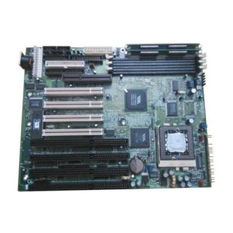
Tyan S1590
Trinity 100AT
Motherboard User's Manual
Revision 1.10
Copyright © Tyan Computer Corporation, 1998. All rights reserved. No part of this
manual may be reproduced or translated without prior written consent from Tyan
Computer Corp.
All registered and unregistered trademarks and company names contained in this
manual are propery of their respective companies including, but not limited to the
following.
AwardBIOS is a trademark of Award Software Inc.
Windows is a trademark of Microsoft Corporation.
IBM, PC, AT, PS/2 are trademarks of IBM Corporation.
INTEL, Pentium, Pentium MMX are trademarks of Intel Corporation.
S1590 Trinity 100AT is a trademark of TYAN Computer Corporation.
Information contained in this publication has been carefully checked for accuracy and
reliability. In no event will Tyan Computer be held liable for any direct or indirect,
incidental or consequential damage, loss of use, loss of data, or other malady resulting
from errors or inaccuracies of information contained in this manual. The information
contained in this document is subject to change without notice.
PRINTED IN USA
Advertisement
Table of Contents

Related Manuals for TYAN Trinity 100AT S1590


Summary of Contents for TYAN Trinity 100AT S1590
- Page 1 Information contained in this publication has been carefully checked for accuracy and reliability. In no event will Tyan Computer be held liable for any direct or indirect, incidental or consequential damage, loss of use, loss of data, or other malady resulting from errors or inaccuracies of information contained in this manual.
-
Page 3: Table Of Contents
Table of Contents 1. Introduction..................4 Overview..................4 Icons..................... 5 Hardware Specifications/Features..........5 Software Specifications.............. 7 Technical Support............... 7 Returning Merchandise for Service.......... 8 2. Board Installation................9 Unpacking..................9 Installation................... 9 Setting Jumpers................20 3. Onboard Resource Settings............22 Quick Reference for Jumpers............ -
Page 4: Introduction
Flexibility and expandability have been designed into the Trinity 100AT. With I/O and drive controller support built onboard, the one AGP slot, four PCI and four ISA slots (one shared, eight usable) are free for numerous add-on expan- sion cards. http://www.tyan.com... -
Page 5: Icons
Remember to take a look at TYAN Computer’s web site located at http://www.tyan.com. There you can find information on all of TYAN’s products along with FAQs, distributors list, drivers, and BIOS setting explana- tions. Icons In order to help you navigate this manual and set up your system, we have added several icons to our format. - Page 6 •Two PCI bus mastering EIDE channels. •Supports EIDE CD-ROMs. •PIO Mode 3+4 (up to 17MB/s DTR). •Bus mastering mode (up to 22MB/s DTR). •Support for two floppy drives (supports Mode 3 and up to 2.88MB). •Two serial ports (16550 UARTs). http://www.tyan.com...
-
Page 7: Software Specifications
Warranty •3 year manufacturer’s warranty. * For the latest CPU compatibility list see www.tyan.com ** Only 384MB SDRAM validated at time of print. For the latest list of approved memory see www.tyan.com Software Specifications •Operates with MS-DOS, Windows 3.x, Windows for WorkGroup 3.x, Windows 95, Windows 98,... -
Page 8: Returning Merchandise For Service
Return Merchandise Authorization (RMA) number. The RMA number should be prominently displayed on the outside of the shipping carton and the package should be mailed prepaid, or hand-carried to the manufacturer. TYAN will pay to have the board shipped back to you. http://www.tyan.com... -
Page 9: Board Installation
Board Installation Unpacking The mainboard package should contain the following: (1) S1590 mainboard (1) 40-pin IDE and 34-pin floppy cable pack (1) S1590 User’s Manual ( 1 ) Serial/parallel cable set ( 1 ) PS/2 mouse cable (1) Driver CD Installation You are now ready to install your mainboard. - Page 10 Install the motherboard into your case. Follow the instructions provided by the case manufacturer for proper installa- tion guidelines. TYAN recommends that you use only one screw to hold down the motherboard. The rest of the mounting holes should be used for the plastic standoffs.
- Page 11 Note: Tyan recommends using an ATX power supply that conforms to industry standard revision 2.01.
- Page 12 Hard drive lights are constantly on: bad IDE cable or defective drive or motherboard. Try another HDD. • Hard drives do not power up: check power cables and cabling. May also be a bad power supply or IDE drive. http://www.tyan.com...
- Page 13 Figure 4 Now that you have installed your IDE drives, your floppies are next. Pin 1 on the floppy cable is usually denoted by a red or colored stripe down one side of the cable (see Figure 6). Most of the current floppy drives on the market require that the colored stripe be positioned so that it is right next to the power connector.
- Page 14 IBM standard pinouts and will differ from most other manufacturers’. Other cables will not work on TYAN boards. The Printer and Com1 ports are on the same back plate. You want to make sure that you correctly align the connectors with the pins on the board beacuse they are easy to miss.
- Page 15 Com2 is supplied seperately on a second back plate (Figure 9). Remem- ber: Only TYAN cables will work on this motherboard. If you are using an existing case with old cables, your system will not function properly. Use only TYAN-approved connectors.
- Page 16 Because of this, your memory may not work correctly in a TYAN board though it may work well in a competitor’s board. http://www.tyan.com...
- Page 17 This is because many of our competitors do not adhere to the strict tolerances required for high performance. If you buy a TYAN board, you are getting the best system available. To make installation easy and trouble free, get high quality parts.
- Page 18 Pin 1 on the ZIF socket is denoted by an angled corner. Never force a CPU into a socket. Forcing a CPU to seat will bend the pins on the CPU and possibly damage the motherboard. Check with your http://www.tyan.com...
- Page 19 CPU. A squeaking noise is normal as the arm lowers. After the CPU is securely seated, install the appropriate cooling device (Figure 13). Tyan strongly recomends a heatsink/ fan combination on the Intel proces- sors. For Cyrix Processors, use the Figure 12...
-
Page 20: Setting Jumpers
The metal rod inside the plastic shell bridges the gap between the two pins, completing the circuit. See the drawings below for examples of “on” and “off” pins and jumpers. 3 (or more) pin jumpers 2 pin jumpers open http://www.tyan.com... - Page 21 This page intentionally left blank. S1590 Trinity 100AT...
-
Page 22: Onboard Resource Settings
The tables on the following pages will help you set the jumpers for CPU speed, InfraRed, and external connector pin assignments, among others. The miniature motherboard maps will help you locate the jumpers on your board. A full-page map of the motherboard can be found on the facing page. http://www.tyan.com... -
Page 23: Map Of Motherboard Jumpers
Map of Motherboard Jumpers Keybrd PS/2 Mouse Award BIOS header AT power connector 3 volt lithium VIA MVP3 battery chipset VIA MVP3 JPW1 chipset JVBAT1 JP11 (Fan) J4 (CPU Fan) JP10 The tiny number “1”s next to jumpers of 3 pins or more indicate the position of pin 1 for that jumper. - Page 24 Chapter 3 Onboard Resource Settings PS/2 mouse port 4 PCI slots 4 ISA slots header Keyboard Award BIOS port 3 DIMM slots ZIF Socket 7 temperature 1MB L2 2 SIMM slots sensor cache http://www.tyan.com...
- Page 25 CPU and memory. You must have a 100MHz processor AND PC/100 memory to run at a bus speed of 100MHz. Tyan does not recommend and is not responsible for functionality or damage to components caused by operating a CPU, memory or important! any bus at higher than rated speeds (overclocking).
-
Page 26: Power Supply Type
Chapter 3 Onboard Resource Settings SIMM Voltage Settings Memory Clock Speed J5 External Pin Assignments a r f Power Supply Type (Fan) JP1,2 (Fan) (CPU Fan) Other Pin Assignments & t i n http://www.tyan.com... -
Page 27: Hardware Cmos & Password Reset
Hardware CMOS & Pass- word Reset If you have been locked out of your system because you forgot your password or set the CMOS incorrectly, follow the instructions below. 1. Power off the system 2. Set jumper JVBAT1 to pins 2 and 3 3. -
Page 28: Cmos Rtc
768MB (Only 384MB validated at time of print. See www.tyan.com for the latest list of qualified memory) of SDRAM. The 168-pin DIMMs must be of the 3.3V, unbuffered variety. The position of the notch in the DRAM key position will tell you whether or not a DIMM is unbuffered (see the figure below). - Page 29 l a t • EDO, SDRAM, Parity, and ECC (using Parity memory) memory is supported. • SIMM modules must be installed in pairs, and both must be of the same size and type. • The mainbord supports 4MB, 8MB, 16MB, 32MB, and 64MB SIMMs. •...
-
Page 30: Cache Memory
Onboard Resource Settings DIMM modules. 256MB modules have not been validated at time of printing. See www.tyan.com for the latest list of qualified memory. • 66MHz or 100MHz SDRAM modules can be used, but you must use 100MHz SDRAMs if you wish to take advantage of the 100MHz Front Side Bus speed. - Page 31 This page intentionally left blank. S1590 Trinity 100AT...
-
Page 32: Bios Configuration
Setup. Starting Setup The EliteBIOS is immediately activated when you first turn on the computer. The BIOS reads system configuration information in CMOS RAM and begins http://www.tyan.com... -
Page 33: Setup Keys
the process of checking out the system and configuring it through the power- on self test (POST). When these preliminaries are finished, the BIOS seeks an operating system on one of the data storage devices (hard drive, floppy drive, etc.). The BIOS launches the operating system and hands control of system operations to it. - Page 34 Chipset screen without a good reason. The Chipset defaults have been carefully chosen by Award Software or your system manufacturer for the best performance and reliability. Even a seemingly small change to the Chipset setup may causing the system to become un- stable. http://www.tyan.com...
-
Page 35: Main Setup Menu
Setup Variations Not all systems have the same Setup. While the basic look and function of the Setup program remains the same for all systems, the appearance of your Setup screens may differ from the screens shown here. Each system design and chipset combination require custom configurations. - Page 36 BIOS defaults are factory settings for the most stable, minimal-performance system operations. Load Setup Defaults Setup defaults are factory settings for optimal-performance system operations. Save & Exit Setup Save settings in nonvolatile CMOS RAM and exit Setup. Exit Without Saving http://www.tyan.com...
-
Page 37: Standard Cmos Setup
Abandon all changes and exit Setup. Standard CMOS Setup In the Standard CMOS menu you can set the system clock and calendar, record disk drive parameters and the video subsystem type, and select the type of errors that stop the BIOS POST. ROM PCI/ISA BIOS (2A5LET59) STANDARD CMOS SETUP AWARD SOFTWARE, INC. - Page 38 LBA (Logical Block Addressing): During drive accesses, the IDE controller transforms the data address described by sector, head, and cylinder number into a physical block address, significantly improving data transfer rates. For drives with greater than 1024 cylinders. http://www.tyan.com...
- Page 39 Drive A, Drive B Select the correct specifications for the diskette drive(s) installed in the computer. e t t l l a v i r o l i y t i y t i v i r y t i v i r o l i y t i...
-
Page 40: Bios Features Setup
This screen contains industry-standard options additional to the core PC AT BIOS. This section describes all fields offered by Award Software in this screen. The example screen below may vary from the one in your Setup program. Your system board designer may omit or modify some fields. http://www.tyan.com... -
Page 41: Virus Warning
ROM PCI/ISA BIOS (2A5LET59) BIOS FEATURES SETUP AWARD SOFTWARE, INC. Virus Warning : Disabled Video BIOS Shadow : Enabled CPU Internal Cache : Enabled C8000-CBFFF Shadow : Disabled External Cache : Enabled CC000-CFFFF Shadow : Disabled Quick Power On Self Test : Disabled D0000-D3FFF Shadow : Disabled Boot Sequence... - Page 42 Gate A20 refers to the way the system addresses memory above 1 MB (extended memory). When set to Fast, the system chipset controls Gate A20. When set to Normal, a pin in the keyboard controller controls Gate A20. Setting Gate A20 to Fast improves system speed, particularly with OS/2 and Windows. http://www.tyan.com...
- Page 43 Memory Parity/ECC Check Select Enabled or Disabled. If Enabled, allows memory checking when the BIOS detects the presence of ECC or Parity DRAM. Typematic Rate Setting When Disabled, the following two items (Typematic Rate and Typematic Delay) are irrelevant. Keystrokes repeat at a rate determined by the keyboard controller in your system.
-
Page 44: Chipset Features Setup
Do not reset these values unless you understand the consequences of your changes. Note: This chapter describes all fields offered by Award Software in this screen. Your system board designer may omit or modify some fields. http://www.tyan.com... -
Page 45: Sdram Cycle Length
ROM PCI/ISA BIOS (2A5LET59) CHIPSET FEATURES SETUP AWARD SOFTWARE, INC. Bank 0/1 DRAM Timing : FP/EDO 70ns OnChip USB : Disabled Bank 2/3 DRAM Timing : FP/EDO 70ns USB Keyboard Support : Disabled Bank 4/5 DRAM Timing : SDRAM 10ns CPU Warning Temperature : Disabled SDRAM Cycle Length Current CPU Temperature : 61C/141F... - Page 46 Slow gives more stable performance. This field applies only when synchronous DRAM is installed in the system. OnChip USB The chipset contains an integrated USB controller. Select Enabled if you have USB peripherals. USB Keyboard Support Select Enabled if you have a USB keyboard. http://www.tyan.com...
-
Page 47: Power Management Setup
Power Management Setup Note: This chapter describes all fields offered by Award Software in this screen. Your system board designer may omit or modify some fields. ROM PCI/ISA BIOS (2A5LET59) POWER MANAGEMENT SETUP AWARD SOFTWARE, INC. ACPI Function : Enabled Primary INTR : ON Power Management... - Page 48 4 seconds, with only enough circuitry receiving power to detect wake-up event activity. ** PM Timers ** The following modes are Green PC power saving functions that are user- configurable only in User Defined Power Management mode. http://www.tyan.com...
- Page 49 HDD Power Down After the selected period of drive inactivity (1 to 15 minutes), the hard disk drive powers down while all other devices remain active. Doze Mode After the selected period of system inactivity (1 minute to 1 hour), the CPU clock runs at slower speed while all other devices still operate at full speed.
- Page 50 The following is a list of IRQs (Interrupt Request Lines) assigned to common system peripherals. IRQ3 (COM2) IRQ10 (Reserved) IRQ4 (COM1) IRQ11 (Reserved) IRQ5 (LPT2) IRQ12 (PS/2 Mouse) IRQ6 (Floppy Disk) IRQ13 (Coprocessor) IRQ7 (LPT1) IRQ14 (Hard Disk) IRQ8 (RTC Alarm) IRQ15 (Reserved) IRQ9 (IRQ2 Redir) http://www.tyan.com...
-
Page 51: Pnp/Pci Setup
PnP/PCI Configuration Note: This chapter describes all fields offered by Award Software in this screen. Your system board designer may omit or modify some fields. ROM PCI/ISA BIOS (2A5LET59) PNP/PCI CONFIGURATION AWARD SOFTWARE, INC. PNP OS Installed : No CPU to PCI Write Buffer : Enabled Resources Controlled By : Auto... - Page 52 When this field is Enabled, writes to the PCI bus are executed with zero wait states. PCI Delay Transaction The chipset has an embedded 32-bit posted write buffer to support delay transaction cycles. Select Enabled to support compliance with PCI specifica- tion version 2.1. http://www.tyan.com...
- Page 53 PCI Master Read Prefetch A prefetch occurs during a read operations process when the controller “peeks” at the next instruction and actually begins the next read instruction. When this field is Enabled, the PCI bus master device is allowed to prefetch the next read instruction and initiate the next read operation.
-
Page 54: Integrated Peripherals
UDMA (Ultra DMA) is a DMA data transfer protocol that utilizes ATA commands and the ATA bus to allow DMA commands to transfer data at a maximum burst rate of 33 MB/s. When you select Auto in the four IDE UDMA http://www.tyan.com... - Page 55 fields (for each of up to four IDE devices that the internal PCI IDE interface supports), the system automatically determines the optimal data transfer rate for each IDE device. Init Display First Select the type of display adapter used in your system. Onboard FDD Controller Select Enabled if your system has a floppy disk controller (FDC) installed on the system board and you wish to use it.
-
Page 56: Password Setting
You can upgrade the BIOS on your motherboard by using the Flash Memory Writer (FMW) utility. This utility can be downloaded from TYAN’s BBS and from the TYAN website. The system BIOS is stored on a flash EEPROM chip on the mainboard, which can be erased and reprogrammed by the FMW. The following three files make up the FMW: AWDFLASH.EXE... - Page 57 cannot upgrade an Award BIOS to an AMI BIOS or vice-versa. Note: You should always clear your CMOS after flashing a BIOS. This will clear out any stray settings from your old BIOS which may have been carried over from the flashing process. Most problems encountered after flashing a BIOS will be solved by this simple procedure (see Hardware CMOS &...
- Page 58 Warning: If you do not successfully install a complete BIOS file in the flash memory on the mainboard, your system may not be able to boot. If this happens, it will require service by your system vendor. Follow the instructions in this section precisely to avoid such an inconvenience. http://www.tyan.com...
- Page 59 This page intentionally left blank. S1590 Trinity 100AT...
-
Page 60: System Resources
BIOS code may have become corrupt. Contact your system dealer to replace the BIOS. CMOS battery failed CMOS battery is no longer functional. Contact your system dealer for a replacement battery. CMOS checksum error - Defaults loaded Checksum of CMOS is incorrect, so the system loads the default equipment http://www.tyan.com... - Page 61 configuration. A checksum error may indicate that CMOS has become corrupt. This error may have been caused by a weak battery. Check the battery and replace if necessary. CPU at nnnn Displays the running speed of the CPU. Display switch is set incorrectly. The display switch on the motherboard can be set to either monochrome or color.
- Page 62 See the Press TAB ... message above for a description of this feature. Secondary master hard disk fail POST detects an error in the primary slave IDE hard drive. Secondary slave hard disk fail POST detects an error in the secondary slave IDE hard drive. http://www.tyan.com...
-
Page 63: Glossary
Glossary ACPI (Advanced Configuration and Power Interface) is a power management specification that allows the operating system to control the amount of power distributed to the computer’s devices. Devices not in use can be turned off, reducing unnecessary power expenditure. (Accelerated Graphics Port) is a PCI-based interface which was de- signed specifically for demands of 3D graphics applications. - Page 64 (that is, the data is transmitted in serial http://www.tyan.com...
- Page 65 ROM chip which can, unlike normal ROM, be updated. This allows you to keep up with changes in the BIOS programs without having to buy a new chip. TYAN’s BIOS updates can be found at http://www.tyan.com/html/drivers.html ESCD (Extended System Configuration Data) is a format for storing informa- tion about Plug and Play devices in the system BIOS.
- Page 66 PCB (personal computer board) or motherboard. The standard form factors are the AT and ATX, although TYAN also makes some Baby-AT boards. Global timer is an onboard hardware timer, such as the Real Time Clock.
- Page 67 Latency is the amount of time that one part of a system spends waiting for another part to catch up. This is most common when the system sends data out to a peripheral device, and is waiting for the peripheral to send some data back (peripherals tend to be slower than onboard system components).
- Page 68 SIMM sockets are the physical slots into which you stick SIMM modules. A pair of SIMM sockets form a SIMM bank, and act as a unit. If only one socket is filled, the bank will not operate. Sleep/Suspend mode , all devices except the CPU shut down. http://www.tyan.com...
- Page 69 SRAM Static RAM, unlike DRAM, does not need to be refreshed in order to prevent data loss. Thus, it is faster, and more expensive. Standby mode , the video and fixed disk drive shut down; all other devices operate normally. UltraDMA/33 is a fast version of the old DMA channel.
- Page 70 Chapter 5 System Resources This page intentionally left blank. http://www.tyan.com...
- Page 71 Notice for the USA Compliance Information Statement (Declaration of Conformity Procedure) DoC FCC Part 15: This Device complies with Part 15 of the FCC Rules. Operation is subject to the following conditions: 1) this device may not cause harmful interference, and 2) this device must accept any interference received including interference that may cause undesired operation.
Need help?
Do you have a question about the Trinity 100AT S1590 and is the answer not in the manual?
Questions and answers