Table of Contents
Advertisement
Quick Links
Tyan S1846
Tsunami ATX
Motherboard User's Manual
Revision 1.60
Copyright © Tyan Computer Corporation, 1999. All rights reserved. No part of this
manual may be reproduced or translated without prior written consent from Tyan
Computer Corp.
All registered and unregistered trademarks and company names contained in this
manual are propery of their respective companies including, but not limited to the
following.
AMIBIOS is a trademark of American Megatrend Incorporated.
Windows is a trademark of Microsoft Corporation.
IBM, PC, AT, PS/2 are trademarks of IBM Corporation.
INTEL, Pentium II, Pentium III, Celeron are trademarks of Intel Corporation.
S1846 Tsunami and Tsunami-ATX are trademarks of TYAN Computer Corporation.
Information contained in this publication has been carefully checked for accuracy and
reliability. In no event will Tyan Computer be held liable for any direct or indirect,
incidental or consequential damage, loss of use, loss of data, or other malady resulting
from errors or inaccuracies of information contained in this manual. The information
contained in this document is subject to change without notice.
PRINTED IN USA.
Advertisement
Table of Contents

Subscribe to Our Youtube Channel
Related Manuals for TYAN Tsunami S1846S


Summary of Contents for TYAN Tsunami S1846S
- Page 1 Information contained in this publication has been carefully checked for accuracy and reliability. In no event will Tyan Computer be held liable for any direct or indirect, incidental or consequential damage, loss of use, loss of data, or other malady resulting from errors or inaccuracies of information contained in this manual.
-
Page 2: Table Of Contents
Table of Contents 1. Introduction....................4 Overview................... 4 Icons....................5 Hardware Specifications/Features..........5 Software Specifications..............7 Technical Support................7 Returning Merchandise for Service..........8 2. Board Installation..................10 Unpacking..................10 Precautions..................10 Installation Steps................11 What is a Jumper?................12 Map of Motherboard Jumpers............. - Page 3 POST Checkpoint Codes.............. 70 Displayed Error Messages............77 Appendix 1 - CPU Retention Module Options.......... 80 Appendix 2 - Glossary.................. 82...
-
Page 4: Introduction
I/O and drive controller support built onboard, the one AGP slot, five PCI and two ISA slots (one shared, seven usable) are free for numerous add-on expansion cards. Remember to take a look at TYAN Computer’s web site located at http://www.tyan.com. There you can find information on all of TYAN’s http://www.tyan.com... -
Page 5: Icons
products along with FAQs, distributors list, drivers, and BIOS setting explana- tions. Icons In order to help you navigate this manual and set up your system, we have added several icons to our format. This icon alerts you to particularly important details regarding the setup or maintenance of your system. - Page 6 •AMI Plug and Play flash BIOS •Deep Green, Energy Star, ACPI, Year 2000, and PC98 compliant •Soft power-down, multiple boot options •Win98/NT5 ready, DMI 2.0 compliant •PCI 2.1, APM 1.1 compliant Disk Drive & System I/O •Two PCI bus mastering EIDE http://www.tyan.com...
-
Page 7: Software Specifications
channels •Supports EIDE CD-ROMs •PIO Mode 3 & 4 (up to 17MB/sec DTR) •UltraDMA/33 bus mastering mode (up to 33MB/sec DTR) •Support for two floppy drives (up to 2.88MB) •Two serial ports (16550 UARTs) •One ECP/EPP parallel port •One IR (InfraRed) I/O interface port •Two USB rev 1.2 (universal serial bus) connectors •One PS/2 mouse connector... -
Page 8: Returning Merchandise For Service
Return Merchandise Authorization (RMA) number. The RMA number should be prominently displayed on the outside of the shipping carton and the package should be mailed prepaid, or hand-carried to the manufacturer. TYAN will pay to have the board shipped back to you. http://www.tyan.com... - Page 9 This page left blank intentionally. S1846 Tsunami ATX...
-
Page 10: Board Installation
Here are some precautions you should follow when installing your motherboard: (1) Ground yourself properly before removing your motherboard from the antistatic bag. Unplug the power from your computer and then touch any metal part on the computer case. (Or wear a grounded wrist strap.) important! http://www.tyan.com... -
Page 11: Installation Steps
(2) Hold the motherboard by its edges and do not touch the bottom of the board. (3) Avoid touching motherboard components, IC chips, connectors, and leads. (4) Avoid touching pins of memory modules and chips. (5) Place motherboard on a grounded antistatic surface or on the antistatic bag. -
Page 12: What Is A Jumper
The miniature motherboard maps will help you locate the jumpers on your board. A full-page map of the motherboard can be found on the next two pages. 3 (or more) pin jumpers 2 pin jumpers open Figure 2-1 Figure 2-2 http://www.tyan.com... -
Page 13: Map Of Motherboard Jumpers
Map of Motherboard Jumpers 3 volt National lithium FAN1 Mouse LM75 battery USB2 Intel 82443BX Ensoniq Audio PCI AGP port PCI slot 1 CON3 JP10 JP11 PCI slot 2 JP12 JP13 CON2 PCI slot 3 Intel 82371EB PCI slot 4 EXTSMI PCI slot 5 Flash BIOS... -
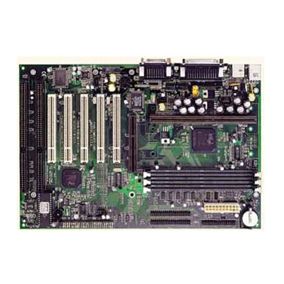
Page 14: Picture Of Motherboard Features
Chapter 2 Board Installation Picture of Motherboard Features Intel 443BX 3 DIMM slots Slot One Connector LM75 LM79 2 ISA slots http://www.tyan.com... -
Page 15: Setting Jumpers
There is no need to set the bus speed. The motherboard auto-detects the bus speed of the CPU. Presently all Celeron CPUs use a 66MHz bus speed. Tyan does not recommend operating CPUs, memory, or PCI Bus at higher than rated speed. Tyan takes no responsibility for any problems related to overclocking any bus or component on the system board. - Page 16 3. Wait for 2 seconds, then return jumper JP3 to pins 1 and 2. FAN1 4. Power on the system again. By following this procedure, you will erase your password and reset the CMOS to the BIOS defaults. FAN2 JP17 JP7, JP8 CON3 FAN3 http://www.tyan.com...
- Page 17 1-E. IR/Floppy Set to 2 FDD if you are using 2 floppy drives. ) t l 1-F. Onboard Sound Enable (S1846SLA only) 1-G. Chassis Intrusion Alarm Connector The J7 connector is an intrusion alarm, that can be connected to the system chassis.
-
Page 18: Mounting The Motherboard In The Chassis
Flash EEPROM The Tsunami ATX uses flash memory to store BIOS firmware. It can be easily updated if necessary using the flash utility (see page 67). Tyan does not recommend flashing the BIOS unnecessarily. Check the Tyan web site for the latest BIOS revision. -
Page 19: Installing Memory
Because of this, your memory may not work correctly in a TYAN board though it may work well in a competitor’s board. This is because many of our competitors do not adhere to the strict tolerances required for high performance. - Page 20 2 GB of SDRAM. The 168-pin DIMMs (Dual In-line Memory Modules) must be of the 3.3V, unbuffered variety. The position of the notch in the SDRAM key position will tell you whether or not a DIMM is http://www.tyan.com...
- Page 21 Figure 2-4 unbuffered (see the Figure 2-5 below). All installed memory will be automati- cally detected, so there is no need to set any jumpers. Unbuffered 168-pin DIMM Buffered Figure 2-5 Some details of memory installation: • At least one unbuffered DIMM must be installed for the system to POST. •...
- Page 22 DO NOT use registered and non-registered memory chips simultaneously! (Check with your memory dealer for more information). warning See www.tyan.com for latest memory compatibility information. Cache Memory Celeron processors have the L2 (Level 2) cache built into their architecture, so there is no need for an L2 cache on the motherboard.
-
Page 23: Installing The Cpu And Cooling Fan
Installing CPU Retention Modules Installation of a Pentium II processor requires a CPU retention module, which is first secured onto the motherboard. Tyan offers a variety of retention mechanisms for the different CPU types. See Appendix 1 for options. Installation of SECC2 CPUs (Figure 2-7) with the retention modules require a little more attention and care. - Page 24 Plug the CPU’s cooling fan cable into the cooling fan connector on the board. There will be a plastic clip assembly similar to that of the ATX power connector that will force you to connect the fan cable correctly (see Figure 2-11 on the following page). http://www.tyan.com...
- Page 25 Figure 2-11 Installing the CPU with Passive Cooling The installation of the CPU with passive cooling differs only slightly from that of the active. Your passive cooling package should contain one CPU retention module, one heat sink retention bracket with mounting locks, two mounting attachments, and one heat sink lock.Install the retention module as explained in the previous section.
- Page 26 CPU enclosure covers only the side faces of the SECC2 Pentium II card. Due to the physical differences in the SECC2 CPU, installing the retention modules requires a different technique than the ones previously discussed. http://www.tyan.com...
- Page 27 SEC Pentium II SECC-2 Pentium II Figure 2-15 On both sides of the SECC-2 CPU reside the lower tabs of the aluminum heat sink and the bottom corners of the plastic CPU enclosure (see Figure 2-16). These tabs and corners should fit into the retention braces. Warning: DO NOT first screw the retention braces onto the motherboard by warning themselves.
- Page 28 Warning - Because the braces are loosely held against the CPU, they can easily fall off. You must hold both braces against the CPU while lifting all three components above the motherboard. (See Figure 2-19 on the following page.) http://www.tyan.com...
- Page 29 Note: board pictured is used only to illustrate installation of CPU & retention mechanism, and may not be a Tiger 100. Figure 2-19 Be sure to line up the holes of the retention brace with the screws protruding from the motherboard. At the same time, make sure the CPU is lined up with the CPU slot.
-
Page 30: Connecting Ide And Floppy Drives
• Hard drive lights are constantly on: bad IDE cable or defective drives/motherboard. Try another HDD. • Hard drives do not power up: check power cables and cabling. May also be a bad power supply or IDE drive. http://www.tyan.com... - Page 31 Pin 1 Figure 2-22 Connecting Floppy Drives Pin 1 on the floppy cable is usually denoted by a red or colored stripe down one side of the cable (see Figure 2-23 below). Most of the current floppy drives on the market require that the colored stripe be positioned so that it is right next to the power connector.
-
Page 32: Connecting The Power Supply
Reverse the cable at the motherboard end and try again. 6. Connecting the Power Supply Tyan recommends using an ATX power supply that conforms to industry standard revision 2.01. The Tomahawk BX/A+ motherboard comes equipped with one onboard power connector. -
Page 33: Installing Add-On Cards
Figure 2-24 Figure 2-25 7. Installing Add-on Cards There are a few rules you need to follow when plugging in a card. In order to assure proper operation and a quick installation, adhere to these guidelines: • If you are going to install a PCI-Bus interface card on your system, be aware that any one of the two PCI slots can support a Master or Slave device. -
Page 34: Connecting Ps/2, Usb, Serial & Parallel Devices
Warning: When plugging in your keyboard and mouse, or when plugging anything into a serial or Com port, make sure that the power is off. Connecting these devices and ports while the power is on is called “hot plugging,” and may damage your system. Figure 2-26 http://www.tyan.com... -
Page 35: Frequently Asked Questions
Com and Printer ports, as well as the other ports, are labeled. The S1846SLA also has Audio connectors (game, line-in, mic, spkr). Note: Only TYAN cables will work on this motherboard. If you are using an existing case with old cables, your system will not function properly. -
Page 36: Bios Configuration
Primary IDE Slave Auto Secondary IDE Master Auto Secondary IDE Slave Auto Auto-Detect Hard Disks [ Enter ] Boot Sector Virus Protection Disabled Previous Item ¯ Next Item ® ¬ Select Menu ESC:Exit Enter:Select F5:Setup Defaults F6:Original Values F10:Save & Exit http://www.tyan.com... -
Page 37: Main Setup
You can select a Setup option by using the following keyboard keys: Function Moves from one box to the next Arrow keys Changes selections within a box Enter Opens highlighted selection The pages which follow contain explanations of the settings for the AMIBIOS Setup menus. - Page 38 CD-ROM: Use for ATAPI Maximum Capacity CD-ROM drives LBA Mode Double click [AUTO] to Block Mode set all HDD parameters Fast Programmed I/O Modes automatically 32 Bit Transfer Mode ON -¯ ESC:Back Enter:Select :Select Items F5:Setup Defaults F6:Original Values http://www.tyan.com...
- Page 39 IDE Device Configuration: To have the BIOS autodetect the IDE drive, select Auto. Otherwise, you may choose one of the 46 drive types offered, or enter the parameters yourself (see Entering Drive Parameters on page 40). Consult the table below to see how to configure various drive types yourself. l l a r u t o l l...
- Page 40 . ) r http://www.tyan.com...
- Page 41 Auto-Detect Hard Disks This option lets the system detect your hard disk(s) automatically for your convenience. Boot Sector Virus Protection The available settings for this option are ‘Enable’ and ‘Disable’. Default Settings Every option in AMIBIOS Setup contains two default values: a Fail-Safe default and the Optimal default value.
-
Page 42: Advanced Cmos Setup
3rd B oot Device AT AP I CDR OM AT AP I CDR OM T ry Other B oot Devices F loppy Acces s Control R ead-Write R ead-Write H ard Dis k Acces s Control R ead-Write R ead-Write http://www.tyan.com... - Page 43 Settings Chart (Continued) Setting Option Optimal Default Fail-Safe Default S .M.A.R .T . for H ard Dis ks Dis abled Dis abled B oot Up Num-Lock P S /2 Mous e S upport E nabled E nabled P rimary Dis play VGA/E GA VGA/E GA P as s word Check...
- Page 44 This option specifies the read-write access that is set when booting from a hard disk drive. The settings are Read-Write or Read-Only. S.M.A.R.T. for Hard Disks Set this option to Enabled to permit AMIBIOS to use the SMART (System http://www.tyan.com...
- Page 45 Management and Reporting Technologies) protocol for reporting server system information over a network. Enabling this feature allows you to back up your data when your hard disk is about to fail. The settings are Enabled or Disabled. Boot Up Num-Lock Set this option to Off to turn the Num Lock key off when the computer is booted so you can use the arrow keys on both the numeric keypad and the keyboard.
- Page 46 The ROM area not used by ISA adapter cards is allocated to PCI adapter cards. The settings are: i t t a s i r e t o i t t t i r . y r http://www.tyan.com...
-
Page 47: Chipset Setup
Chipset Setup Choose Chipset Setup on the AMIBIOS Setup main menu. All Chipset Setup options are then displayed. AMIBIOS Setup can be customized. AMIBIOS Setup can be customized via AMIBCP. See the AMIBIOS Utilities Guide for additional information. AMI BIOS EASY SETUP UTILITY Ver.1.16 (c)1998 American Megatrends, Inc. - Page 48 Normal IS A Normal IS A DMA-7 T ype Normal IS A Normal IS A * Setting option not selectable. USB Function Set this option to Enabled to enable USB (Universal Serial Bus) support. The settings are Enabled or Disabled. http://www.tyan.com...
- Page 49 USB KB/Mouse Legacy Support Set this option to Enabled to enable support for older keyboards and mouse devices if the USB Function option is set to Enabled. The settings are Enabled or Disabled. Port 64/60 Emulation Setting this option to Enabled allows a USB keyboard to act like a legacy keyboard.
- Page 50 DRAM system memory access cycle when SDRAM system memory is installed in this computer. The settings are Auto, 2 SCLKs, or 3 SCLKs. Power Down SDRAM If this option is set to Enabled, the SDRAM Power Down feature is enabled. The settings are Enabled or Disabled. http://www.tyan.com...
- Page 51 ACPI Control Register Set this option to Enabled to enable the ACPI (Advanced Configuration and Power Interface) control register. The settings are Enabled or Disabled. The Optimal and Fail-safe default settings are Enabled. Gated Clock Set this option to Enabled to enable the gated clock. The settings are Enabled or Disabled.
- Page 52 This option provides selective CPU Bus Frequency; however, it is strongly recommended that the default setting (Auto) be selected. Unpredictable situations may arise if the Intel default CPU bus speed is not used. The settings are Auto, 66.8MHz, 68.5MHz, 75MHz, 83.3MHz, 100MHz, 103MHz, or 112MHz. http://www.tyan.com...
-
Page 53: Power Management Setup
Power Management Setup The AMIBIOS Setup options described in this section are selected by choosing Power Management Setup from the AMIBIOS Setup main menu. AMI BIOS EASY SETUP UTILITY Ver.1.16 (c)1998 American Megatrends, Inc. All Rights Reserved Advanced Advanced CMOS Setup [ Enter ] Setup Help Advanced Chipset Setup [ Enter ] Power Management Setup [ Enter ]... - Page 54 . f f t t u r e t l l u Green PC Monitor Power State This option specifies the power state that the green PC-compliant video monitor enters when AMIBIOS places it in a power saving state after the http://www.tyan.com...
- Page 55 specified period of display inactivity has expired. The settings are Off, Stand By, or Suspend. Video Power Down Mode This option specifies the power state that the video subsystem enters when AMIBIOS places it in a power saving state after the specified period of display inactivity has expired.
- Page 56 If this option is Enabled, the CPU fan will turn off when the system is in Suspend mode. If Disabled, the CPU fan will remain on while the system is in Suspend mode. The settings are Enabled or Disabled. http://www.tyan.com...
-
Page 57: Plug And Play/Pci Setup
RTC Wake-up If Enabled, this option allows you to set an hour and minute for the system to wake up. The next two fields allow you to choose the wake up time. Note that the time fields will not be available if this option is set to Disabled. In order for this wake up function to work, the system must have been brought up at least past the POST before it was last shut down (i.e. - Page 58 P CI/P nP P CI/P nP IR Q1 4 P CI/P nP P CI/P nP IR Q1 5 P CI/P nP P CI/P nP R es erved Memory S ize Dis abled Dis abled * Setting option is not selectable http://www.tyan.com...
- Page 59 Plug and Play Aware O/S Set this option to Yes to inform AMIBIOS that the operating system can handle plug and Play (PnP) devices. The settings are No or Yes. PCI Latency Timer (PCI Clocks) This option specifies the latency timings (in PCI clocks) for PCI devices installed in the PCI expansion slots.
- Page 60 IRQ must be available for PCI and PnP devices. The settings are ISA/EISA or PCI/PnP. Reserved Memory Size This option specifies the size of the memory area reserved for legacy ISA adapter cards. The settings are Disabled, 16K, 32K, or 64K. http://www.tyan.com...
- Page 61 Reserved Memory Address This option specifies the beginning address (in hex) of the reserved memory area. The specified ROM memory area is reserved for use by legacy ISA adapter cards. This option does not appear if the Reserved Memory Size option is set to Disabled.
-
Page 62: Peripheral Setup
LM79 IN6 -6.20 -6.20 Onboard F DC Auto Auto Onboard S erial P ort 1 3F 8h 3F 8h Onboard S erial P ort 2 2F 8h 2F 8h S erial P ort 2 Mode Normal Normal *IR Duplex Mode http://www.tyan.com... - Page 63 Default Settings Chart (Continued) Setting Option Optimal Default Fail-Safe Default *IR R eceiver P in IR R X1 IR R X1 Onboard P arallel P ort P arallel P ort Mode Normal Normal *E P P Vers ion P arallel P ort IR Q *P arallel P ort DMA Channel Onboard IDE B oth...
- Page 64 This option specifies the Enhanced Parallel Port specification version number that is used in the system. This option only appears if the Parallel Port Mode option is set to EPP. The settings are 1.7 or 1.9. Version 1.9 is common on http://www.tyan.com...
- Page 65 newer devices; consult your device’s user information for the appropriate port type. There are no default settings. Parallel Port IRQ This option specifies the IRQ used by the parallel port, and only appears if OnBoard Parallel Port is set to 278 or 378. The settings are 5 or 7. Parallel Port DMA Channel This option is only available if the setting for the Parallel Port Mode option is set to ECP and the OnBoard Parallel Port option is set to 378, 278, or 3BC.
-
Page 66: Supervisor And User Security
When you select the Supervisor Security option, a dialog box will appear, allowing you to enter a password. You may either type the password in, or click on the onscreen buttons. Your password must be between one and six characters long. http://www.tyan.com... -
Page 67: Language Utility
Once you have entered your new password, you will be asked to confirm it. If the two passwords do not match, you will be prompted to enter a new pass- word, and then to confirm it. This will continue until you enter the same series of characters both times. -
Page 68: System Resources
If AMIBIOS POST can initialize the system video display, it displays the error message. Displayed error messages, in most cases, allow the system to continue to boot. Displayed error messages are described on pages 75-76. See the top of the next page for the beep code chart. http://www.tyan.com... -
Page 69: Troubleshooting System Problems
e r f u l i e r f c r i t i u . y t y t i y t i t s r . y r u l i u l i t s r i a f r u l t s r , y r... -
Page 70: Post Checkpoint Codes
. l u r a t n i t Uncompressed Initialization Codes The following routine checkpoint codes are listed in order of execution. These codes are uncompressed in F000h shadow RAM. The table begins on the next page. http://www.tyan.com... - Page 71 SYSTEM...
- Page 72 . t x i r e e i f t f o n i r t f o s i h t i s o i t . t x http://www.tyan.com...
- Page 73 . t e n i r . t x . t e e z i . t x . t x e t r . t e t s r e z i . t x e z i e t r n i r .
- Page 74 . t x i n I a i t z i l i t a e t f . e t . t x . t x http://www.tyan.com...
- Page 75 t f o . t x n i t c i t . t x c i t . t e t a t . t x . r e n i r i l b y t i . t x y t i i n i a i t...
- Page 76 I a i t z i l i t a . r e http://www.tyan.com...
-
Page 77: Displayed Error Messages
Displayed Error Messages If an error occurs after the system display has been initialized, the error message will be displayed as follows: ERROR Message Line 1 ERROR Message Line 2 Press <F1> to continue and the system will halt. The system will not halt if the Wait for <F1> If Any Error option in Advanced Setup is Disabled. - Page 78 . t o : s i y t i y t i . y r : s i y t i y t i . s s y t i http://www.tyan.com...
- Page 79 This page intentionally left blank. S1846 Tsunami ATX...
-
Page 80: Appendix 1 - Cpu Retention Module Options
Appendix 1 CPU Retention Module Options CPU Retention Module Options Tyan offers two different options for securing Intel’s Pentium II CPUs onto the motherboard. Each option provides retention for both older Pentium II’s as well as newer Pentium II’s (including Celeron). - Page 81 OPTION 2: One universal retention module is included in the motheboard package. This type of retention module adapts to both old and new Pentium II CPUs - see Figure 3. (Screws for the retention modules are provided) Figure 3 S1846 Tsunami ATX...
-
Page 82: Appendix 2 - Glossary
AT form factor. It improves on the AT design by rotating the board ninety degrees, so that the IDE connec- tors are closer to the drive bays, and the CPU is closer to the power supply http://www.tyan.com... - Page 83 and cooling fan. The keyboard, mouse, serial, USB, and parallel ports are built Bandwidth refers to carrying capacity. The greater the bandwidth, the more data the bus, phone line, or other electrical path, can carry. Greater bandwidth, then, also results in greater speed. (Bulletin Board System) is a computer system with a number of modems hooked up to it which acts as a center for users to post messages and access information.
- Page 84 Dynamic RAM is a widely available, very affordable form of RAM which has the unfortunate tendency to lose data if it is not recharged regu- larly (every few milliseconds). This refresh requirement makes DRAM three to ten times slower than non-recharged RAM such as SRAM. http://www.tyan.com...
- Page 85 ROM chip which can, unlike normal ROM, be updated. This allows you to keep up with changes in the BIOS programs without having to buy a new chip. TYAN’s BIOS updates can be found at http://www.tyan.com/html/drivers.html ESCD (Extended System Configuration Data) is a format for storing informa- tion about Plug and Play devices in the system BIOS.
- Page 86 (PCI Programmable Input/Output) modes are the data transfer modes used by IDE drives. These modes use the CPU for data transfer (DMA channels do not). PCI refers to the type of bus used by these modes to communicate with the CPU. http://www.tyan.com...
- Page 87 PCI-to-PCI bridge allows you to connect multiple PCI devices onto one PCI slot. Pipeline burst SRAM is a fast secondary cache. It is used as a secondary cache because SRAM is slower than SDRAM, but usually larger. Data is cached first to the faster primary cache, and then, when the primary cache is full, to the slower secondary cache.
- Page 88 Zero Insertion Force sockets make it possible to insert CPUs without damaging the sensitive pins. The CPU is lightly placed in an open ZIF socket, and the metal lever pulled down. This shifts the processor over and down, guiding it into place on the board. http://www.tyan.com...
- Page 89 Notice for the USA Compliance Information Statement (Declaration of Conformity Procedure) DoC FCC Part 15: This Device complies with Part 15 of the FCC Rules. Operation is subject to the following conditions: 1) this device may not cause harmful interference, and 2) this device must accept any interference received including interference that may cause undesired operation.
Need help?
Do you have a question about the Tsunami S1846S and is the answer not in the manual?
Questions and answers