Advertisement
Table of Contents
Advertisement
Table of Contents

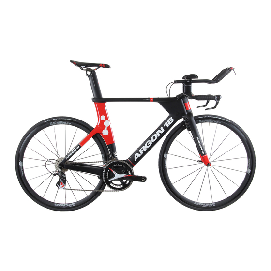
Summary of Contents for Argon 18 E-118
- Page 1 E-118 Assembly Guide...
-
Page 2: Table Of Contents
8 . Saddle adjustment . . . . . . . . . . . . . . . . . . . . . . . . . . . . . . . . . . . . . . . . . . . . . . . . . . . . . . . . . . . . . .16 For the warranty to be valid, the bicycle must be fully assembled by an authorized Argon 18 dealer. -
Page 3: Overview Of The Assembly
Overview of the assembly 1 . Fork installation 2 . Cable housing installation 3 . Handlebar installation 4 . Front brake installation IMPORTANT NOTICE: DON’T INSTALL THE BB BEFORE THE CABLE HOUS- ING INSTALLATION) 5 . Rear brake installation 6 . Handlebar assembly 7 . -
Page 4: Fork Installation
1. Fork installation 1 . Screw the compressor inside the stem until it disappears completely 2 . Install the bearings inside the frame by using grease GREASE GREASE... - Page 5 1. Fork installation 1 . Install the fork on the frame 2 . Place the dust cover on the upper bearing 3 . Screw the compressor with a 6mm hex key to adjust the pressure on the bearings 4 . While maintaining the compressor with the hex key, apply some Loctite®...
-
Page 6: Cable Housing Installation
2. Cable housing installation 1 . Install the rear derailleur cable housing starting at the drive side’s drop-out 2 . Install the front derailleur cable housing starting under the bottom bracket shell 3 . Install the front brake cable housing starting at the center of the handlebar 4 . -
Page 7: Handlebar Installation
Install the handlebar as shown in the diagram above, make sure to The AHB-7500 handlebar is designed grease the screws and to apply specifically for the E-118. Do not use some carbon fiber assembly gel any other type of handlebar as safety or in the clamping area . performance cannot be guaranteed with... -
Page 8: Front Brake Installation
4. Front brake installation 1 . Install the brake as shown in the diagram - Install the spring in the middle hole of the fork insert - It is important not to mix the springs of the front and rear brakes the short end of the spring should be positioned in - Respect the color code: the spring... -
Page 9: Rear Brake Installation
5. Rear brake installation 1 . Remove the brake arm stopper GREASE 2 . Install the brake as shown in the diagram - Install the spring in the middle hole of the fork insert 3 . Install the brake arm stopper and adjust the set screw on the brake arm to avoid any... - Page 10 5. Rear brake installation 1 . Finalize the installation of the brake by placing the cover of the bottom bracket as shown in diagram...
- Page 11 6. Handlebar assembly GREASE 1 . Install the extension connectors as shown in the diagram - Ensure that the lower bracket positioned correctly (see diagrams below) FIG 1 - Make sure you use the correct bolt length for the required number of spacers FIG 1 Correct installation of the...
-
Page 12: Handlebar Assembly
6. Handlebar assembly (configuration for the inversed handlebar: + 5cm) GREASE 1 . Follow the directions of the regular configuration GREASE... - Page 13 6. Handlebar assembly CARBON FIBER ASSEMBLY GEL GREASE GREASE 1 . Cut the extension bars the desired lengths and apply some carbon fiber assembly gel in the clamping area 2 . Insert the extension bars into the connectors and insert the shim under the extension bars . Make sure the shims are centered on the set screw FIG 2...
- Page 14 6. Handlebar assembly 1 . Install the adhesive velcro on the carbon armrests 2 . Screw the armrests to the connectors according to the desired position . Reverse the left and the right armrest to obtain a more forward or backward setup .
-
Page 15: Seatpost Installation
7. Seatpost installation CARBON FIBER ASSEMBLY GEL 1. Peel off the plastic of the double- sided tape located at the back of the seat clamp thread 2 . Place the seat clamp thread inside the frame 3 . Insert the seatpost on which some carbon fiber assembly gel has been applied 4 . -
Page 16: Saddle Adjustment
8. Saddle adjustment 1 . Install the saddle on the rocker and lightly tighten the rail clamp using a ball end hex key 2 . Tighten the upper screw of the rocker clamp by keeping a space of 2 to 3 mm between the aluminum and carbon parts 2-3 mm gap 3 . - Page 17 11i Set screw E-118 Handle Bar 11j Flat Washer 5b E-118 J bar 12 TKB-78* front brake Quantity E-118 extension bar 25mm rise including the following parts 5d E-118 extension holders 1 left + 1 right E-118 armrest 12a Brake arms...


Need help?
Do you have a question about the E-118 and is the answer not in the manual?
Questions and answers