Table of Contents
Advertisement
Quick Links
OPERATOR'S MANUAL
HIGH POWER BIPOLAR POWER SUPPLY
KEPCO INC.
An ISO 9001 Company.
IMPORTANT NOTES:
1)
This manual is valid for the following Firmware Versions:
FIRMWARE VERSION
4.12 and higher
2)
A Change Page may be included at the end of the manual. All applicable changes and
revision number changes are documented with reference to the equipment serial num-
bers. Before using this Instruction Manual, check your equipment firmware version num-
ber to identify your model. If in doubt, contact your nearest Kepco Representative, or the
Kepco Documentation Office in New York, (718) 461-7000, requesting the correct revision
for your particular model and firmware version number.
3)
The contents of this manual are protected by copyright. Reproduction of any part can be
made only with the specific written permission of Kepco, Inc.
Data subject to change without notice.
©2015, KEPCO, INC
P/N 243-1027-r18g
KEPCO, INC. 131-38 SANFORD AVENUE FLUSHING, NY. 11355 U.S.A. TEL (718) 461-7000 FAX (718) 767-1102
BOP-MG 1KW
MODEL
BOP-MG 1KW
POWER SUPPLY
ORDER NO.
email: hq@kepcopower.com World Wide Web: http://www.kepcopower.com
NOTE.
KEPCO
THE POWER SUPPLIER™
®
Advertisement
Chapters
Table of Contents

Subscribe to Our Youtube Channel
Related Manuals for KEPCO BOP-MG 1KW


Summary of Contents for KEPCO BOP-MG 1KW
-
Page 1: Power Supply
Data subject to change without notice. KEPCO ® ©2015, KEPCO, INC P/N 243-1027-r18g THE POWER SUPPLIER™ KEPCO, INC. 131-38 SANFORD AVENUE FLUSHING, NY. 11355 U.S.A. TEL (718) 461-7000 FAX (718) 767-1102 email: hq@kepcopower.com World Wide Web: http://www.kepcopower.com... -
Page 3: Declaration Of Conformity
Standard to which Conformity is declared: EN61010-1:1993 (Safety requirements for electrical equipment for measurement, control and laboratory use) Manufacturer's Name and Address: KEPCO INC. 131-38 SANFORD AVENUE FLUSHING, N.Y. 11355 USA Importer's Name and Address: Type of Equipment: Component Power Supply Model No.:... - Page 4 There are no user or operator serviceable parts within the product enclosure. Refer all servicing to qualified and trained Kepco service technicians. 228-1529 COND/CONFORM 111315...
-
Page 5: Safety Instructions
SAFETY INSTRUCTIONS 1. Installation, Operation and Service Precautions This product is designed for use in accordance with EN 61010-1 and UL 3101 for Installation Category 2, Pollution Degree 2. Hazardous voltages are present within this product during normal operation. The prod- uct should never be operated with the cover removed unless equivalent protection of the operator from accidental contact with hazardous internal voltages is provided: There are no operator serviceable parts or adjustments within the product enclosure. -
Page 6: Safety Messages
Service must be referred to authorized personnel. Using the power supply in a manner not specified by Kepco. Inc. may impair the protection provided by the power supply. Observe all safety precautions noted throughout this manual. The following table lists symbols used on the power supply or in this manual where applicable. - Page 7 LIST OF WARNINGS AND CAUTIONS PAGE WARNING/CAUTION WARNING: 3-20 For inductive loads, and especially superconducting magnet type loads, the inherent offset of the BOP in the OFF state may generate significant current in the circuit. A properly rated switch in parallel with a resistor must be connected between the power supply and the load.
- Page 8 LIST OF WARNINGS AND CAUTIONS PAGE WARNING/CAUTION CAUTION: it is recommended that source power of external equipment connected to the Analog Port be applied through an isolating transformer To avoid ground loops or possible damage to the BOP due to incorrect equipment a-c wiring (e.g., defeating of ground connection).
-
Page 9: Warnings And Cautions
LIST OF WARNINGS AND CAUTIONS PAGE WARNING/CAUTION 3-19 CAUTION: When working with active loads, always adjust the BOP protection limits to be above the maximum values of voltage or current expected from the load. For example, when the BOP is operating in voltage mode sinking energy from a constant current type load, set the current protection limits of the BOP above the maximum current expected from the load. -
Page 11: Table Of Contents
TABLE OF CONTENTS SECTION PAGE SECTION 1 - INTRODUCTION Scope of Manual ............................. 1-1 General Description..........................1-1 Specifications ............................1-1 Local Control ............................1-12 Remote Control ............................1-12 Features ..............................1-15 1.6.1 Digital Calibration..........................1-15 1.6.2 voltage/current Protection........................1-15 1.6.3 Waveforms............................ - Page 12 TABLE OF CONTENTS SECTION PAGE SECTION 3 - OPERATION General ..............................3-1 Power Supply Basics ..........................3-1 3.2.1 Keypad Description........................... 3-1 3.2.2 LCD and Power-up Screen Description .................... 3-3 3.2.3 Turning the Power Supply On......................3-5 3.2.4 How to Access the menus ........................ 3-6 3.2.4.1 How to Modify a Parameter......................
- Page 13 TABLE OF CONTENTS SECTION PAGE 3.4.1 Remote Output off ..........................3-38 3.4.1.1 Remote Shutdown ........................3-38 3.4.1.2 Remote Standby .......................... 3-39 3.4.2 Voltage/Current Mode Control ......................3-40 3.4.3 Controlling the Output Using the BOP as a Power Amplifier ............. 3-40 3.4.3.1 Fixed Gain using External Reference Control................
- Page 14 TABLE OF CONTENTS SECTION PAGE 3.6.3.11 CALibrate Subsystem ......................... 3-60 3.6.3.12 System Subsystem ........................3-60 3.6.3.12.1 Forgotten Passwords ......................3-60 3.6.4 Program Message Structure ......................3-61 3.6.4.1 Keyword ............................3-62 3.6.4.2 Keyword Separator ........................3-62 3.6.4.3 Query Indicator..........................3-62 3.6.4.4 Data.............................
- Page 15 TABLE OF CONTENTS SECTION PAGE CAL Commands and Queries ........................ B-2 iate ediate INIT [:IMM ] Command ......................B-3 iate inuous INIT :CONT Command ......................B-4 iate inuous INIT :CONT Query......................... B-4 MEAS [:SCAL ]:CURR [:DC]? Query..................B-4 MEAS [:SCAL ]:MODE[:DC] Command ..................
- Page 16 TABLE OF CONTENTS SECTION PAGE B.62 [SOUR :]LIST:DWEL :POIN ? Query....................B-17 B.63 [SOUR :]LIST:QUER Command......................B-17 B.64 [SOUR :]LIST:QUER ? Query ......................B-17 B.65 [SOUR :]LIST:REP Command ....................... B-18 olution B.66 [SOUR :]LIST:RES ? Query...................... B-18 B.67 [SOUR :]LIST:SAMP :CURR Command..................
- Page 17 TABLE OF CONTENTS SECTION PAGE tionable B.120 STAT :QUES :ENAB Command..................B-31 us:questionable B.121 STAT :ENAB ? Query ....................B-32 B.122 SYST :BEEP Command........................B-33 unication B.123 SYST :COMM :GPIB:ADDR Command ................ B-33 unication B.124 SYST :COMM :GPIB:ADDR ? Query................B-33 unication B.125 SYST...
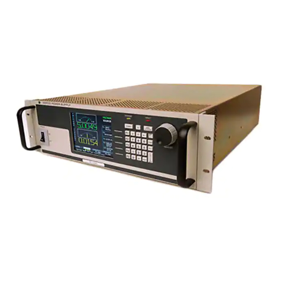
- Page 18 LIST OF FIGURES FIGURE TITLE PAGE High Power BOP Series Power Supply......................x 1000W BOP Power Supply, Outline Drawing..................... 1-13 BOP Output Characteristics ........................1-19 BOP Series Rear Panel..........................2-1 Earth Ground Connection Recommendations.................... 2-10 Load Connections, Local Sensing......................2-13 Load Connections, Remote Sensing......................
- Page 19 LIST OF TABLES TABLE TITLE PAGE BOP 1000 Watt Model Parameters ......................1-1 BOP General Specifications ........................1-2 Equipment Supplied ............................1-16 Accessories ..............................1-17 Safety Symbols ............................1-18 Rear Panel Connector Functions ........................2-2 IEEE 1118 Connector Input/Output Pin Assignments .................2-2 Trigger Port Pin Assignments ........................2-3 External Protection Connector Input/Output Pin Assignments ..............2-3 RS232C PORT Input/Output Pin Assignments ...................2-4 Parallel/Serial Control Out Port Pin Assignments ..................2-4...
- Page 20 FIGURE 1-1. HIGH POWER BOP SERIES POWER SUPPLY BOP-1K 111315...
-
Page 21: Scope Of Manual
This manual contains instructions for the installation, operation and servicing of the BOP series of 1000 Watt rack-mounted, 4-quadrant bipolar, programmable, voltage and current stabilized d- c power supplies manufactured by Kepco, Inc., Flushing, New York, U.S.A. NOTE:This manual does not apply to units with Firmware Rev less than 2.0. -
Page 22: Bop General Specifications
TABLE 1-2. BOP GENERAL SPECIFICATIONS SPECIFICATION RATING/DESCRIPTION CONDITION INPUT CHARACTERISTICS a-c voltage nominal 200/220/230/240Va-c No setting required. Single phase or between (200-240 Va-c) 2 phases of a 3-phase system within 200- 240Va-c. range 176 - 264 Va-c Continuous; Input voltage outside range causes protection fault. - Page 23 TABLE 1-2. BOP GENERAL SPECIFICATIONS (Continued) SPECIFICATION RATING/DESCRIPTION CONDITION OUTPUT CHARACTERISTICS (Continued) Digital Programming Voltage 14 bits / 0.03% 3% accuracy for Ext Ref Level (see PAR. resolution / accuracy 3.4.3.2). Unit gain adjustable between 0 and Current 14 bits / 0.1% (voltage) or I O (current).
- Page 24 TABLE 1-2. BOP GENERAL SPECIFICATIONS (Continued) SPECIFICATION RATING/DESCRIPTION CONDITION OUTPUT CHARACTERISTICS (Continued) Master/slave Maximum of identical 3 units, Series operation up to 300V max. Parallel operation Master/slave Maximum of 5 identical units 2 series x 2 parallel Master/slave for both series and parallel Series-parallel Operation 3 series x 2 parallel branches of identical units...
- Page 25 TABLE 1-2. BOP GENERAL SPECIFICATIONS (Continued) SPECIFICATION RATING/DESCRIPTION CONDITION PROGRAMMING/DISPLAY CHARACTERISTICS (Continued) External Protection Port External Shutdown Isolated input for shutdown of the Pulse width: 100 S min. (see Table 2-4) BOP (latched status) Action delay: 100 S max Restore operation by cycling input power or pressing RESET key.
- Page 26 TABLE 1-2. BOP GENERAL SPECIFICATIONS (Continued) SPECIFICATION RATING/DESCRIPTION CONDITION FUNCTION GENERATOR CHARACTERISTICS (See PAR. 3.3.9) Maximum number of waveforms Local: 16 Local: Saved for power-up Remote: 1 Remote: Lost when the unit is turned off, must be saved on the host computer) Maximum number of segments or basic wave- Local: 10 Or maximum number of points (whichever...
- Page 27 TABLE 1-2. BOP GENERAL SPECIFICATIONS (Continued) SPECIFICATION RATING/DESCRIPTION CONDITION FUNCTION GENERATOR CHARACTERISTICS (Continued) Basic waveform parameters Sine: Frequency (Hz), Amplitude (Vp-p or Ap-p), Offset (Vd-c or Ad-c), Start Phase (°), Stop Phase (°). Triangular: Frequency (Hz), Amplitude (Vp-p or Ap-p), Offset (Vd-c or Ad-c), Start Phase (°), Stop Phase (°).
- Page 28 TABLE 1-2. BOP GENERAL SPECIFICATIONS (Continued) SPECIFICATION RATING/DESCRIPTION CONDITION FUNCTION GENERATOR CHARACTERISTICS (Continued) Frequency: Not applicable to Level Range (Hz) 0.001 to 443 Sine, Triangle 0.02 to 532 ±Ramp 0.02 to 1000 Square Programming Resolution (Hz) 0.001 Sine, Triangle 0.01 Ramp, Square Accuracy 1.5% of Frequency...
- Page 29 TABLE 1-2. BOP GENERAL SPECIFICATIONS (Continued) SPECIFICATION RATING/DESCRIPTION CONDITION FUNCTION GENERATOR CHARACTERISTICS (Continued) Amplitude Accuracy Main Channel Voltage 0.03% E O and Offset Current 0.1% I O Protection Limit. Current 0.5% I O Channel. Voltage 0.3% E O Distortion (THD-F, Total Harmonic Distortion 5% max.
- Page 30 Types Factory defaults: Main: DEFAULT, Password Main, Admin1, Admin2 Admin1: none assigned, Admin2: KEPCO Protection Choices Unprotected, Main, Admin1, Admin2 Password menu always protected by Admin2 Items Protected Interface, max/min , Load type, Test, Multiple unit configurations are protected by Calibration, Power-up, Keypad @ Admin2 password.
- Page 31 TABLE 1-2. BOP GENERAL SPECIFICATIONS (Continued) SPECIFICATION RATING/DESCRIPTION CONDITION GENERAL (ENVIRONMENTAL) CHARACTERISTICS Temperature operating 0 to +50 deg C Full rated load storage -20 to +85 deg C Cooling Two internal fans exhaust to the rear Humidity 0 to 95% RH non-condensing Shock 20g.
-
Page 32: Local Control
LOCAL CONTROL Either the front panel keypad or the adjust control can set and adjust output voltage and current under local control. The display provides a digital display of output voltage and current as well as a pictorial display of real-time analog voltage and current meters. The keypad includes five function keys which provide access to the menu-driven functions of the unit. -
Page 33: W Bop Power Supply, Outline Drawing
18.805 [477.63] 18.018 [457.64] 17.675 [448.93] 16.835 [427.60] OBROUND 0.25x0.453 (4 LOC.) 18.235 [463.16] 18.985 [482.21] FIGURE 1-2. 1000W BOP POWER SUPPLY, OUTLINE DRAWING (SHEET 1 OF 2) 1-13 BOP HIPWR 111315... -
Page 34: Rear View
REAR VIEW REMOVE FEET FOR RACK MOUNTING. 22.000 [558.79] SLIDES TRAVEL DISTANCE: 23.000 [584.2] SEE NOTE 6. FIGURE 1-2. BOP POWER SUPPLY, OUTLINE DRAWING (SHEET 2 OF 2) 1-14 BOP HIPWR 111315... -
Page 35: Features
FEATURES 1.6.1 DIGITAL CALIBRATION The BOP Power Supply contains no internal adjustments. Calibration is done entirely via the keypad (or remotely via the GPIB or RS 232 interface) using digital entries and a calibrated DVM, a precision d-c reference voltage source and precision shunt resistor. Calibration instruc- tions appear on the front panel after a password is entered;... -
Page 36: External Reference (Analog Control)
ITEM FUNCTION PART NUMBER Source Power Entry mating connector Mates with source power entry connector 142-0381 (Kepco) (IEC 320) PAR/SER CONTROL - IN Mates with PAR/SER CONTROL - IN port to allow 142-0488 (Kepco) mating connector access to pins required for calibration... -
Page 37: Accessories
Accessories for the BOP Power Supply are listed in Table 1-4. TABLE 1-4. ACCESSORIES ITEM FUNCTION PART NUMBER Mating Connector, Trigger Mates with Trigger port. 142-0527 (Kepco) SP2501 (CUI Stack) IEEE 1118 (BITBUS) Allows connection to IEEE 1118 (BITBUS) port. 142-0485 (Kepco) Mating connector KMDLA-5P (Kycon Inc.) IEEE 488 Cable, (1 meter long) Connects BOP power supply to GPIB bus. -
Page 38: Safety
Service must be referred to authorized personnel. Using the power supply in a manner not specified by Kepco. Inc. may impair the protection provided by the power supply. Observe all safety precautions noted throughout this manual (see listing on page E, preceding the Table of Contents). -
Page 39: Bop Output Characteristics
FIGURE 1-3. BOP OUTPUT CHARACTERISTICS 1-19/(1-20 Blank) BOP HIPWR 111315... -
Page 41: Section 2 - Installation
SECTION 2 - INSTALLATION UNPACKING AND INSPECTION This instrument has been thoroughly inspected and tested prior to packing and is ready for operation. After careful unpacking, inspect for shipping damage before attempting to operate. Perform the preliminary operational check as outlined in PAR. 2.3. If any indication of damage is found, file an immediate claim with the responsible transport service. -
Page 42: Rear Panel Connector Functions
TABLE 2-1. REAR PANEL CONNECTOR FUNCTIONS NUMBER CONNECTOR/TERMINAL FUNCTION (FIGURE 2-1) (REFERENCE DESIGNATOR) IEEE 1118 (BITBUS) PORT Used for multiple identical BOP master/slave parallel, and series and series-parallel (connector A1J4) configurations (refer to PAR. 2.8, see Table 2-2). TRIGGER May be used to initiate BOP output. (See Table 2-3.) (connector A1J3) IEEE 488 (GPIB) PORT Used for Remote control of the BOP via the IEEE 488 (GPIB) interface (See Table 2-... -
Page 43: Trigger Port Pin Assignments
TABLE 2-3. TRIGGER PORT PIN ASSIGNMENTS CONNECTOR SIGNAL NAME FUNCTION LOGIC GND Return for TRIGGER and SHUTDOWN signals. SHUTDOWN Operation of pin 2 is controlled by OUTP:CONT command (PAR. B.15): STANDBY, HIGH, LOW, DISABLED. OUTPUT ON-OFF Factory default is STANDBY upon power-up: Logic 0 ((0 volts ... -
Page 44: Rs232C Port Input/Output Pin Assignments
TABLE 2-5. RS232C PORT INPUT/OUTPUT PIN ASSIGNMENTS CONNECTOR SIGNAL NAME FUNCTION Request To Send (protocol not used) Receive Data RS 232 Transmit Data PORT LOGIC GND Logic Ground A1J5 LOGIC GND Logic Ground Clear To Send (protocol not used) TABLE 2-6. PARALLEL/SERIAL CONTROL OUT PORT PIN ASSIGNMENTS CONNECTOR SIGNAL NAME FUNCTION... -
Page 45: Parallel/Serial Protect In Port Pin Assignments
TABLE 2-8. PARALLEL/SERIAL PROTECT IN PORT PIN ASSIGNMENTS CONNECTOR SIGNAL NAME FUNCTION SD_A Anode of LED optocoupler which is part of protection circuit for parallel or series combination. Cathode of LED is connected to PARALLEL/ SERIAL PROTECT OUT PORT (A2A5J2) pin 1 (see Table 2-9). When activated, the optocoupler shuts down the unit. -
Page 46: Preliminary Operational Check
TABLE 2-10. ANALOG I/O PORT INPUT/OUTPUT PIN ASSIGNMENTS CONNECTOR SIGNAL NAME FUNCTION CAUTION: it is recommended that source power of external equipment connected to the Analog Port be applied through an isolating transformer To avoid ground loops or possible damage to the BOP due to incorrect equipment a-c wiring (e.g., defeating of ground connection). -
Page 47: Ieee 488 Port Input/Output Pin Assignments
2. With no load connected, set POWER switch to the ON position. Each time the unit is turned on an internal self-test is performed. The alphanumeric display (LCD) shows the processor firmware revision history and lists various tests performed during the internal self-test. As each test is completed, PASS or FAIL is displayed. -
Page 48: Installation
The user must provide aproperly sized and rated mains lead (line cord) and service with a current rating compatible with the anticipated input current. Line cords available as accessories are listed in Table 1-4. Kepco recommends #12 AWG (2,0 mm diameter) for input line cord. -
Page 49: Earth-Ground Configuration
It is hoped that the preceding paragraphs will be of some assistance in most cases. For help in special applications or difficult problems, consult directly with Kepco's Application Engineering Department. 2.5.3.1... -
Page 50: Earth Ground Connection Recommendations
ANALOG I/O PORT BOP 1KW PROGRAMMING DEVICE LOAD SGND ANALOG I/O PORT BOP 1KW PROGRAMMING DEVICE LOAD CORRECT! SGND ANALOG I/O PORT BOP 1KW PROGRAMMING DEVICE LOAD SGND ANALOG I/O PORT BOP 1KW With two earth-ground points as PROGRAMMING DEVICE shown, a ground loop allows return current to flow through the internal LOAD... -
Page 51: Grounding Network Configuration
2.5.3.2 GROUNDING NETWORK CONFIGURATION When the output is floating there is a tendency for large changes in output voltage to affect the digital programming section, possibly resulting in an erroneous output. Decoupling capacitors from each of the two output terminals to the chassis via a terminal block link form a grounding network. -
Page 52: Load Connection Using Local Sensing
NOTE REGARDLESS OF OUTPUT CONFIGURATION, EITHER LOCAL OR REMOTE OUT- PUT SENSE LINES MUST BE CONNECTED FOR OPERATION. 1. OBSERVE POLARITIES: The OUT S sensing wire must be connected to the OUT- PUT load wire, and the COM S sensing wire must be connected to the COMMON load wire. -
Page 53: Setup For Local Operation
2.7.2 SETUP FOR LOCAL OPERATION With all power off, connect the load to the BOP using either local or remote sensing (refer to PAR. 2.5). If units are to be connected in series or parallel, refer to PAR. 2.8.) Then refer to PAR. 3.2 for power supply basics and local operation. -
Page 54: Setup For Remote Operation Via Gpib
N / C FIGURE 2-4. LOAD CONNECTIONS, REMOTE SENSING 2.7.3 SETUP FOR REMOTE OPERATION VIA GPIB With all power off, connect the load to the BOP using either local or remote sensing. If units are to be connected in series or parallel, refer to PAR. 2.8. Connect the GPIB connector to the GPIB port (see Figure 2-1 and Table 2-1). -
Page 55: Multiple Unit Configurations
NOTE: Multiple unit configurations require that all individual units be properly calibrated. (Units shipped from Kepco have been factory-calibrated.) If not, refer to Section 4 to calibrate the individual units prior to connecting them in parallel or series. Using calibrated units ensures that the multiple unit configuration is calibrated;... -
Page 56: Parallel Configuration, Local Sensing, Typical
FIGURE 2-5. PARALLEL CONFIGURATION, LOCAL SENSING, TYPICAL 2-16 BOP HIPWR 111315... -
Page 57: Parallel Configuration, Remote Sensing, Typical
FIGURE 2-6. PARALLEL CONFIGURATION, REMOTE SENSING, TYPICAL 2-17 BOP HIPWR 111315... -
Page 58: Series Configuration, Local Sensing, Typical
N / C N / C N / C FIGURE 2-7. SERIES CONFIGURATION, LOCAL SENSING, TYPICAL 2-18 BOP HIPWR 111315... -
Page 59: Series Configuration, Remote Sensing, Typical
N / C N / C N / C FIGURE 2-8. SERIES CONFIGURATION, REMOTE SENSING, TYPICAL 2-19 BOP HIPWR 111315... -
Page 60: Multiple Unit Protection
2.8.2 MULTIPLE UNIT PROTECTION For multiple unit configurations it is necessary to configure the protection so that a fault will shut down all the interconnected power supplies. Figure 2-9 is a simplified diagram showing typical interconnections for master/slave configurations. 2.8.3 MULTIPLE UNIT SOURCE POWER When multiple units are connected in series or parallel, the individual power supplies of the sys- tem may be connected to different phases of a 3-phase a-c power source. -
Page 61: Configuring Parallel, Series, 2 X 2 Or 3 X 2 Combinations
2.8.4 CONFIGURING PARALLEL, SERIES, 2 X 2 OR 3 X 2 COMBINATIONS 1. To configure a unit to be designated as a slave proceed as follows: a. Turn on power only to the unit to be designated as a slave. b. -
Page 62: Powering Up Series/Parallel Combinations
CAUTION: The units are now configured as slave(s) to be controlled only by the master. Do not use the slave keypad, RS 232 port or GPIB port to try to control the slave(s). 2. Repeat step 1 as necessary to configure all slaves, but at step d highlight applicable SLAVE # as appropriate. - Page 63 “No Answer” means the slave is not responding to requests from the master. Possible causes are a) slave not powered up, b) bitbus cable not installed correctly or c) slave number incorrect. “Mode Error” can be caused a) if the slave does not match voltage (for parallel) or current (for series) of the master or b) the slave is not configured to series or parallel to match the configura- tion expected by the master.
-
Page 64: Master Power Up Screen
VOLTAGE VOLTAGE CURRENT SOURCE CPROTECT FIGURE 2-10. MASTER POWER UP SCREEN TABLE 2-13. SLAVE STATUS MESSAGE DEFINITIONS Slave Status Message Displayed on Master Power Up Screen MEANING (see Figure 2-10) Ready Unit is ready for operation. If unit’s FAULT indicator is off, hardware error has NOT been detected, STANDBY output is ready to be turned on No Answer... -
Page 65: Operating Instructions For Multiple Unit Combinations
VOLTAGE SOURCE FIGURE 2-11. POWER ON DEFAULT SCREEN FOR MASTER UNIT VOLTAGE SOURCE 0.0000 FIGURE 2-12. POWER ON DEFAULT SCREEN FOR SLAVE UNIT 2.8.6 OPERATING INSTRUCTIONS FOR MULTIPLE UNIT COMBINATIONS 1. Apply power to the multiple units. If the master is in STANDBY, depress STANDBY key on the master to apply power to the output terminals. -
Page 66: Restoring A Unit To Standalone Operation
• When the master is turned on, the unit initially displays the Serial number as well as the Firmware Revision levels and power up test results for the Display, Interface and Analog processors, then displays the Master Power Up screen (Figure 2-10). •... -
Page 67: X 2 (3 Series X 2 Parallel) Configuration, Local Sensing, Typical
N / C N / C N / C N / C N / C N / C FIGURE 2-13. 3 X 2 (3 SERIES X 2 PARALLEL) CONFIGURATION, LOCAL SENSING, TYPICAL 2-27/(2-28 Blank) BOP HIPWR 111315... -
Page 69: Section 3 - Operation
BOP (see PAR. 3.6, Appendix A and Appendix B) or 2) CIIL commands (for compatibility with older Kepco products). Operation in remote mode can be simplified by the use of the VISA driver (see PAR. 3.5.5). -
Page 70: Front Panel Keypad
TABLE 3-1. FRONT PANEL CONTROLS AND INDICATORS NUMBER CONTROL/INDICATOR FUNCTION (FIGURE 3-1) POWER ON/OFF Applies source power to unit circuit breaker A7CB1 Displays output voltage and current as well as information in response to Alphanumeric/graphic Display keypad and ADJUST control entries. Displays function of soft function (LCD) keys F1 through F5, and displays information as required to perform all local functions. -
Page 71: Lcd And Power-Up Screen Description
TABLE 3-2. SPECIAL KEY FUNCTIONS FUNCTION The STANDBY key toggles the unit between output on (enabled, STANDBY indicator off) and output off (disabled, STANDBY indicator on). When on, the output goes to the programmed settings. Behavior of the STANDBY unit in Standby (Output off) is determined by the options chosen for Load Type (see PAR. 3.3.6). The default Load Type is ACTIVE, i.e., in STANDBY the unit is set to voltage mode, voltage is set to zero, cur- rent protection is set to the nominal, and voltage limit is set to maximum. -
Page 72: Power-Up Screen Showing Graphic Meters
VOLTAGE 0000 FIGURE 3-3. POWER-UP SCREEN SHOWING GRAPHIC METERS VOLTAGE 0000 FIGURE 3-4. POWER-UP SCREEN SHOWING TIME LINE GRAPH When in Voltage mode, the power supply will (within the configured and rated limits) provide the programmed output voltage. Current is determined by the load, and cannot exceed the Current Protect limits. -
Page 73: Turning The Power Supply On
When in Sink mode, the power supply is operating as an electronic load, absorbing and recu- perating the energy of an active load. Recuperated energy is passed back into the a-c source power line. Mode displayed at the upper right is VOLTAGE SINK when the unit is in voltage mode and an external constant current is injected into the BOP. -
Page 74: How To Access The Menus
If the display is not viewable, press twice. The display will cycle through the range of con- trast settings. Press again to lock in the preferred contrast. To select between the meter (Figure 3-3) and time line (Figure 3-4) displays refer to PAR. 3.2.5.4. -
Page 75: How To Modify A Parameter
• • Analog Remote Settings (Table 3-15): Reference input (internal/external/external reference level), protec- tion limit (internal/external/lesser limit), external mode (enable/disable) • - General Setup (Figure 3-6) • • Interface Settings (Table 3-16): Data format (SCPI/CIIL), GPIB address (default = 6), *RST sets Output (on/off), Device clear (SCPI/MATE), Serial Baud (Off/9600/19200), Xon/Xoff (enable/disable), prompt (enable/disable) •... -
Page 76: How To Access A Password Protected Menu
To change any password you must enter the Admin 2 password to access the Password Menu. The unit is shipped with the Admin 2 password set to “KEPCO,” the Main Unit password set to ”DEFAULT,” and the Admin 1 password is not assigned. To change the password or to protect one of the protected menus, proceed as follows: 1. -
Page 77: Operator Convenience Functions (Display Menu)
1. Enter the first character of the password using the keypad or ADJUST control (see PAR. 3.2.4.1 for entry of alphanumeric characters). (To change the password, refer to PAR. 3.2.4.2.) 2. Press to move to the next character and repeat step 1 for the next character of the pass- word. -
Page 78: Displaying Programmed Settings In Remote Mode
To change the background, press from the power-up screen, Highlight Background, press , highlight Black or White, then to save. Press exit and save for power-up or apply the changes (without saving for power-up) and exit. TABLE 3-3. DISPLAY (OPERATOR CONVENIENCE) MENU FUNCTIONS CHOICES SETTING FUNCTION... -
Page 79: Enabling/Disabling Audible Beeps
3.2.5.3 ENABLING/DISABLING AUDIBLE BEEPS From the power-up screen (Figure 3-3), press , then refer to Table 3-3 and modify the setting using the techniques described in PAR. 3.2.4). Even though audible beeps are set to off, the beeps will still sound upon power-up or detection of a power supply fault. 3.2.5.4 DISPLAYING METERS OR GRAPH (TIME LINE) The top screen can be configured to either display graphical analog meters (Figure 3-3) show-... -
Page 80: Local Password Protection At Power-Up
3.3.1.2 LOCAL PASSWORD PROTECTION AT POWER-UP It is possible to require a password before the front panel controls can function when the unit is powered up. From the power-up screen, press , highlight password, then . Enter Admin 2 password (see PAR. 3.2.4.3) and press to verify. -
Page 81: Voltage And Current Parameter Definitions
Use the ADJUST control to increase or decrease the main channel setting (e.g., volt- age when the unit is in voltage mode). Start with the most significant digit of the desired value, then use to highlight the next digit. For fine adjustment press the ADJUST control in while rotating the knob to modify the least significant digit. -
Page 82: Selecting Bipolar/Independent Protection Limits
TABLE 3-4. VOLTAGE AND CURRENT PARAMETER DEFINITIONS (CONTINUED) To modify refer to PAR. Term Definition Local Remote Minimum (box) Current mode only. Minimum (positive) setting for +Voltage Protect and +Voltage Protect Min maximum (maximum negative) setting for –Voltage Protect. Values of ±Volt- –Voltage Protect Max age Protect between +Voltage Protect Min and –Voltage Protect Max (near zero) are not allowed. -
Page 83: General Setup Menu
VOLTAGE CURRENT VOLTAGE 0.0000 0.0000 SOURCE FIGURE 3-6. GENERAL SETUP MENU VOLTAGE CURRENT VOLTAGE 0.0000 0.0000 SOURCE FIGURE 3-7. MAX/MIN SETTINGS MENU Selection of Bipolar does not immediately change the protect limit values; it changes how the protect settings are displayed and set from the power-up screen. So if maximum/minimum pro- tection limits were set to different values, (e.g, for BOP 36-28MG, current mode, no load, +V Protect Max = 25V and –V Protect Min = 7V) when BIPOLAR is selected, the previous protec- tion values (+25, –7) will remain in place until a new value is entered in the Voltage Protection... -
Page 84: Understanding Voltage And Current Protect Limits
3.3.3.2 UNDERSTANDING VOLTAGE AND CURRENT PROTECT LIMITS These values are the references for the complementary channels: voltage in current mode and current in voltage mode. The range for these values is between a minimum (box) value (see Fig- ure 1-3) and 1% above the rated nominal value (see PAR. 3.3.4.2). If the unit is in voltage mode, it will enter current protect mode when the load demands more current and energy than permit- ted by the ±current protect settings. -
Page 85: Changing Maximum Accepted Voltage Or Current (Main Channel Software Limits)
TABLE 3-5. MAX/MIN SETTINGS MENU CHOICES SETTING FUNCTION (BOLD = Factory Default) Protect Entry BIPOLAR BIPOLAR - Causes a single protection limit value (one for voltage, one for cur- INDEPENDENT rent) to apply to both ± limits. Only one value is displayed and edited from the front panel. -
Page 86: Changing Maximum/Minimum Protection Software-Controlled Limits
capable of delivering ±28A in current mode can be configured to allow current to be adjusted from –0.5A to +10A by setting –Current Min to –0.5 and +Voltage Max to +10. Adjustment range is between 0 and E for voltage and 0 and I for current. -
Page 87: External Limits
CAUTION: When working with active loads, always adjust the BOP protection limits to be above the maximum values of voltage or current expected from the load. For example, when the BOP is operating in voltage mode sinking energy from a constant current type load, set the current protection limits of the BOP above the maximum current expected from the load. -
Page 88: Power Supply Behavior When Output Is Set To Off
TABLE 3-6. POWER SUPPLY BEHAVIOR WHEN OUTPUT IS SET TO OFF LOAD TYPE If unit was in Voltage Mode when output OFF If unit was in Current Mode when output OFF SETTING command issued. command issued. • Unit remains in voltage mode. •... -
Page 89: Battery Charging/Discharging Using The Bop
WARNING Accessing the BOP after the output is disabled in BATTERY mode is hazardous because (1) high current arcing is possible and (2) either the external battery voltage, or the voltage (±Voltage Protection max) on the BOP output terminals may be dangerous. Therefore, for battery and constant-voltage-type active electronic loads it is recommended that two properly rated external switches be installed for safety: one in series with the battery, and one across the BOP output. -
Page 90: 3.3.6.1.2 Battery Operations Using Current Mode
The BOP output voltage is set to the desired battery voltage and current limit is set to the required charging current value. The BOP will go into current limit, charging the battery with a constant current. As the battery's voltage nears the BOP voltage setpoint, the BOP will switch to voltage mode when the battery voltage reaches the “capture”... -
Page 91: Changing The Default Power Up Settings
If current mode is needed, Kepco can modify the unit to establish the voltage limit feedback loop to use the Sense terminals, rather than the Monitor terminals. The modified unit behaves similar to that described for voltage mode except that voltage accuracy is 12-bit/ 0.3%, versus 14-bit/ 0.1% for voltage mode. -
Page 92: Storing/Recalling Power Supply Output Settings
These settings can be directly applied to a load upon power-up. Many other configurable set- tings can be saved for power up using the key after modifying the setting TABLE 3-7. EXAMPLES SHOWING HOW POWER-UP SETTINGS FUNCTION Power-up condition (output ON) Main Protection Mode... -
Page 93: Save/Recall Menu
If the reference type is ExtRefLvl (instead of Internal or External), the uppercase V or A is replaced by lowercase v or a. The protection setting is listed under the Prot heading. TABLE 3-8. SAVE/RECALL MENU CHOICES PARAMETER FUNCTION (BOLD = Factory Default) NOTE: DEFAULT values for empty cells are the settings of the unit at the time the save/recall menu is entered. -
Page 94: Viewing Saved Settings
channel is current, the protection settings are determined by pin 6 (negative voltage protection) and pin 14 (positive voltage protection). 3.3.8.2 VIEWING SAVED SETTINGS 1. Pressing from the power-up screen displays the Saved Setups screen (Figure 3-8) con- sisting of a list of locations 1 through 20 arranged in two columns of 10 rows. Use keys to display additional columns. -
Page 95: Copying Previously Saved Settings To A New Location
5. Continue to modify parameters as described in step 4 above. When all parameters have been modified, press to save for power-up. Press to exit without storing the changes. NOTE: If the message CHANGES NOT ALLOWED is displayed, the memory location has been remotely locked (see PAR. -
Page 96: Understanding How Waveforms Are Generated
Each waveform has an identifying name, the operating mode (voltage or current), positive and negative protection values, and the count (the number of times the complete waveform is to be repeated). Setting the count to zero allows the waveform to repeat continuously. A waveform is comprised of at least one, or as many as 10 segments. -
Page 97: Sine, Triangle And Ramp Waveform Frequency Vs. Points
either reducing the number of segments, or increasing the frequency of the existing segments until the point total is acceptable. TABLE 3-9. SINE, TRIANGLE AND RAMP WAVEFORM FREQUENCY VS. POINTS Frequency Frequency (See Notes 1, 2, and 3) (See Notes 1, 2, and 3) Total Points Total Points From... -
Page 98: Waveform Specifications
3.3.9.4 WAVEFORM SPECIFICATIONS Refer to Table 1-2 for specifications applicable to waveforms created either locally, using the BOP front panel (Local) or remotely from a host computer, using LIST commands (Remote). Dif- ferences between local and remote operation are highlighted. 3.3.9.5 VIEWING STORED WAVEFORMS After observing the precautions of PAR. -
Page 99: Modifying Previously Stored Waveforms
programmed waveform. The BOP will complete the waveform cycle and leave the output at the last point of the waveform. This is chosen using the display menu see Table 3-3. To change the Waveform Stop setting, press from the power-up screen (Figure 3-3), High- light Waveform Stop, press , highlight Standby, Last Level or Current Lvl, then to save. -
Page 100: Waveform Segment Details Menu
2. Assign a name to the waveform: highlight Name, press to modify, change the name using the keys or ADJUST or the multiple presses of the numeric keys (see PAR. 3.2.4.1 for details). Press to save or to abort.the change and exit. TABLE 3-11. -
Page 101: Using Segments To Build A Waveform
3. Refer to Table 3-12 and enter the desired settings for Mode, Positive and Negative Protec- tion and Count. These settings apply to all waveform segments. (Note that the setting for mode cannot be changed once it has been saved; to change the mode, create a new wave- form.) For each parameter listed in Table 3-12 use or ADJUST to highlight the parameter, then press... -
Page 102: Sample Waveform
FIGURE 3-11. SAMPLE WAVEFORM 2. The initial waveform settings are displayed (see Table 3-11 and Table 3-12 for parameter details. Use to modify the initial settings for the waveform. For each parameter, use to save the setting. Name CAP CHARG Mode VOLTAGE Protection... -
Page 103: Copying A Waveform
Period (Sec) 0.001 Offset When all settings are complete, press to save for power-up. This step creates a 1.5V level of 1ms prior to the 0V level. This segment is automatically set to Initial since the previ- ous segment is set to Initial. The first two segments form a positive 2ms, pulse, delayed 1ms from the start of execution. -
Page 104: Reset
3.3.10 RESET CAUTION: Pressing RESET will cause voltage transients to appear at the output which may damage a connected load. Switch is recessed to prevent inadvertent activation. Pressing RESET causes the power supply to execute a complete power on sequence to reset the power supply to the power up settings (see PAR. -
Page 105: Error Message Explanations
TABLE 3-14. ERROR MESSAGE EXPLANATIONS ERROR MESSAGE EXPLANATION General Multiple Decimal places not supported Decimal key was pressed while to the right of the existing decimal point. Exceeding Maximum Allowed Value To check maximums, go to power-up screen, press , highlight Max/Min Settings, press Sign does not affect Protection Limits Protection Limit field is positive or negative, numerical value does not need sign Entry incomplete, Depress ENTER... -
Page 106: Analog Remote Mode Programming
TABLE 3-14. ERROR MESSAGE EXPLANATIONS (CONTINUED) ERROR MESSAGE EXPLANATION Entry not Empty, Use F1 to change. pressed while a previously saved waveform was highlighted. Use to modify or highlight Empty and press for a new waveform. Under Minimum allowed value Frequency or period was too small. -
Page 107: Remote Standby
FIGURE 3-13. REMOTE SHUTDOWN USING INTERNAL POWER, STANDALONE UNITS FIGURE 3-14. REMOTE SHUTDOWN USING INTERNAL POWER, MULTIPLE UNITS, 3.4.1.2 REMOTE STANDBY A standalone unit or a multiple unit configuration (parallel, series or series-parallel) can be set to STANDBY status by applying a remote signal to the TRIGGER PORT as shown in Figure 3-15. For multiple unit configurations this signal must be applied to the master. -
Page 108: Voltage/Current Mode Control
3.4.2 VOLTAGE/CURRENT MODE CONTROL The mode of operation, voltage or current, can be programmed externally by applying a signal at pin 2, referenced to pin 9, of the Analog I/O port. Applying a TTL logic 1 (or open circuit) pro- grams the unit to voltage mode. -
Page 109: Variable Gain Using External Reference Level
1. From the power-up screen, press , highlight Reference Input and press . Highlight External and press to save. Then press to apply the changes (without saving for power-up) and exit. NOTE: This setting can be saved for power-up only by using the pass- word-protected Power-up Settings menu (see {PAR. -
Page 110: External Protection Limits
2. To return to digital or local control, from the power-up screen, press , then highlight Ref- erence Input and press . Highlight Internal and press to save. Then press apply the changes (without saving for power-up) and exit. NOTE: Each time the Reference Input setting is changed, the unit generates an internal *RST reset command (see PAR. -
Page 111: Using Both Local/Digital And External Protection Limits
• –V_LIM_EXT (pin 6) - This +1V to +10V analog signal sets the negative voltage protect limit from 10% of the nominal value to –full scale voltage. +10V corresponds to rated minimum (maximum negative) voltage (e.g., for BOP 36-28MG, +10V sets negative volt- age limit to –36V). -
Page 112: Operating Features Available Only By Remote Commands
3.5.2.1 PROGRAMMING VOLTAGE/CURRENT LIMIT AND CURRENT/VOLTAGE LIMIT Kepco's auto-crossover digital supplies can operate in either voltage mode with current limit, or current mode with voltage limit. The operating mode is determined by the voltage and current commands received, as well as the load. Each time voltage and current commands are received, the unit must evaluate the commands and the load conditions to determine the neces- sary operating mode. -
Page 113: Making Sure The Previous Command Is Complete
3.5.2.2 MAKING SURE THE PREVIOUS COMMAND IS COMPLETE Some SCPI commands require a flash memory update and can take an indeterminate amount of time to complete. These commands are: • *SAV (**) • MEM:PACK (**) • MEM:UPD • CAL:COPY • CAL:SAVE •... -
Page 114: Remote Mode Setup
The BOP can be substituted for a standard BOP that is currently being used with one of Kepco’s BIT cards, however there are differences in operation (see PAR. 3.5.3.4 and 3.5.3.5. -
Page 115: Gpib Port Setup
SCPI (Standard Commands for Programmable Instruments) - see PAR. Data Format CIIL 3.6. and Appendix B. CIIL - Provides compatibility with early Kepco power supplies and con- trollers. GPIB Address 0 - 30 (06) Assigns address used by external GPIB controller to communicate with BOP. -
Page 116: 3.5.3.1.2 Configure Device Clear (Dcl) Control
3.5.3.1.2 CONFIGURE DEVICE CLEAR (DCL) CONTROL The device clear (DCL) and selected device clear can be set to operate in two modes. In the MATE mode, when the device clear is received, the output of the power supply is set to zero volts. -
Page 117: Establish Communication Language
Enable - Enables Serial Prompt (see PAR. 3.5.6.2.3 for a description of prompt mode). Disable - Disables Prompt. If both Serial XON/XOFF and Prompt functions are disabled, Echo mode is the default (see PAR. 3.5.6.2.2 for a description of Xon/Xoff mode). Enab+echo - Enables Serial Prompt (see PAR. -
Page 118: 3.5.3.5.3 Trigger Operation Differences In Bit 4886
3.5.3.5.3 TRIGGER OPERATION DIFFERENCES IN BIT 4886 The BOP/BIT 4886 only supports *TRG while the BOP 1KW supports TRIGGER:SOURCE EXTERNAL, BUS and IMMEDIATE. The command TRIG:SOUR BUS must be sent before using trigger in the BOP 1KW. 3.5.4 IEEE 488 (GPIB) BUS PROTOCOL Table 3-17 defines the interface capabilities of the BOP 1KW power supply (Talker/Listener) rel- ative to the IEEE 488 (GPIB) bus (reference document ANSI/IEEE Std 488: IEEE Standard Digital Interface for Programmable Instrumentation) communicating with a Host Computer—Controller... -
Page 119: Bop Visa Instrument Driver
Status Byte Sent 3.5.5 BOP VISA INSTRUMENT DRIVER The VISA instrument driver for the BOP power supply, available for download at www.kepco- power.com/drivers.htm, simplifies programming with a VISA compatible GPIB controller. Included are: • source code (C) for all VISA functions (kp_bophi.c) •... -
Page 120: Rs232-C Operation
3.5.6 RS232-C OPERATION The BOP may be operated via an RS232-C terminal, or from a PC using a terminal emulation program. The default settings are as follows: • Baud rate: • Parity: None • Data Bits • Stop Bits • Prompt DISABLE •... - Page 121 FIGURE 3-17. RS 232 IMPLEMENTATION Only seven control characters (characters between 00 and 1F ) are acknowledged by the power supply: • Carriage Return (CR, 0D • Line Feed (LF, 0A • Back Space (BS, 08 • Escape (ESC, 01B •...
-
Page 122: 3.5.6.2.1 Xon Xoff Method
All non-control characters are sent via the serial port of the command originator. The control character BS is echoed as BS Space BS. Only the first control character is returned in response to either a CR LF or LF CR character sequence (see Figure 3-17). 3.5.6.2.1 XON XOFF METHOD The XON XOFF method allows the BOP to control when the command originator is allowed to send data. -
Page 123: Scpi Programming
If each of the above steps is completed successfully, the problem lies in the computer hard- ware and/or software. Refer to the Product Support area of the Kepco website for additional information regarding RS 232 communications problems: www.kepcopower.com/support. -
Page 124: Common Commands/Queries
3.6.2 COMMON COMMANDS/QUERIES Common commands and queries are defined by the IEEE 488.2 standard to perform overall power supply functions (such as identification, status, or synchronization) unrelated to specific power supply operation (such as setting voltage/current). Common commands and queries are preceded by an asterisk (*) and are defined and explained in Appendix A (see Table 4-4). -
Page 125: Tree Diagram Of Scpi Commands Used With Bop Power Supply
ROOT : (colon) SYSTem subsystem ABORt subsystem STATus subsystem SYSTem ABORt STATus :BEEP :OPERation :COMM INITiate subsystem :CONDition? :GPIB:ADDR val :ENABle val INITiate :GPIB:ADDR? :ENABle? [:IMMediate] :SER [:EVENt]? :CONTinuous bool :BAUD :PRESet :CONTinuous? :BAUD? :QUEStionable :ECHO :CONDition? CALibrate subsystem :ECHO? :ENABle val CALibrate... - Page 126 ROOT : (colon) [SOURce:] subsystem LIST subsystem [SOURce:] [SOURce:] LIST CURRent VOLTage :CLEar [:LEVel] [:LEVel] :COUNt val [:IMMediate] [:IMMediate] :COUNt? [:AMPLitude] val [:AMPLitude] val :COUNt:SKIP int [:AMPLitude]? MIN, MAX [:AMPLitude]? MIN, MAX :COUNt:SKIP? :TRIGgered :TRIGgered :CURRent val,val [:AMPLitude] val [:AMPLitude] val APPLy type,val1,val2,val3 [:AMPLitude]? [:AMPLitude]?
-
Page 127: Measure Subsystem
3.6.3.5 MEASURE SUBSYSTEM This query subsystem returns the voltage and current measured at the power supply's output terminals. 3.6.3.6 OUTPUT SUBSYSTEM This subsystem controls the power supply's voltage and current outputs 3.6.3.7 MEMORY SUBSYSTEM This subsystem controls the Flash Memory used by the BOP microprocessors and is used for storing setup parameters and for storing a list for later recall and execution The unit’s configuration, voltage and current, saved setups (*SAV and *RCL command) and Cal- ibration values are stored in Flash Memory. -
Page 128: Source:]Voltage And [Source:]Current Subsystems
If the password is lost, it is possible to enable the password interface by sending SYST:PASS:CEN POWERSUPPLIER Once enabled, the passwords can be set to the default values SYST:SEC:OVERRIDE This restores the passwords to the following: Main: DEFAULT Admin2: KEPCO Admin1: (none assigned) 3-60 BOP HIPWR 111315... -
Page 129: Program Message Structure
3.6.4 PROGRAM MESSAGE STRUCTURE SCPI program messages (commands from controller to power supply) consist of one or more message units ending in a message terminator. The message terminator is not part of the syntax; it is defined by the way your programming language indicates the end of a line (“newline” charac- ter). -
Page 130: Keyword
3.6.4.1 KEYWORD Keywords are instructions recognized by a decoder within the BOP, referred to as a “parser.” Each keyword describes a command function; all keywords used by the BOP are listed in Figure 3-18. Each keyword has a long form and a short form. For the long form the word is spelled out com- pletely (e.g. -
Page 131: Data Separator
• new line (<NL>), ASCII 10 (decimal) or 0A (hex) NOTE: Kepco power supplies require a message terminator at the end of each program mes- sage. The examples shown in this manual assume a message terminator will be added at the end of each message. Where a message terminator is shown it is represented as <NL>... -
Page 132: Program Message Syntax Summary
Each time the parser encounters a keyword separator, the parser moves to the next indented level of the tree diagram. As an example, the STATus branch is a root level branch that has three sub-branches: OPERation, PRESet, and QUEStionable. The following illustrates how SCPI code is interpreted by the parser: STAT:PRES<NL>... -
Page 133: Status Reporting
3.6.7 STATUS REPORTING The status reporting of the BOP power supply follows the SCPI and IEEE 488.2 requirements. The serial poll response of the BOP power supply provides summary bits of the status and error reporting system. The simplest status report is the command valid reporting and data availabil- ity, This successful decoding of a command string generates no error and is indicated by the bit 3 of the serial poll response being a zero. - Page 134 • 12 - List Complete — 1 indicates the programmed list has been completed. Not readable in OPERation Status Condition register. • 13 - Not Used — always zero. • 14 - List Running — 1 indicates the programmed list is in progress. •...
-
Page 135: Questionable Status Register
3.6.7.3 QUESTIONABLE STATUS REGISTER The QUEStionable condition register (see Figure 3-20) contains status bits representing data/signals which give an indication of the quality of various aspects of the signal. A bit set in the QUEStionable condition register indicates that the data currently being acquired or generated is of questionable quality due to some condition affecting the parameter associ- ated with that bit. -
Page 136: Typical Example Of Bop Power Supply Program Using Scpi Commands
/**************************************************************************/ /* Sample Program For KEPCO power supply, using National Instruments */ /* GPIB interface card and IBM PC or compatible computer /**************************************************************************/ #include <stdio.h> #include "decl.h" char rd_str[80]; // Input buffer char dat_str[80]; // Output buffer int bd,adr; main() { adr = ibfind("DEV6");... -
Page 137: Section 4 - Calibration
SECTION 4 - CALIBRATION GENERAL This section contains the calibration instructions for the Power Supply. It is recommended that the user be familiar with Local Mode operation (PAR.3.2) before calibrating the unit. A full calibration consist of a voltage calibration and a current calibration. Both voltage and cur- rent calibrations consist of zero, max and min, and protection limit calibration. -
Page 138: Test Equipment Requirements
(together) TEST EQUIPMENT REQUIREMENTS Table 4-2 lists sense resistors recommended for measuring current and includes Kepco and Manufacturer’s part numbers. The value of the sense resistor chosen should be known with 0.001% accuracy. If other than a recommended sense resistor is to be used, it must be rated for at least 100W power dissipation (actual power dissipation will be approximately 10W). -
Page 139: Suggested Sense Resistors
NOTE: Selected sense resistor must be mounted on a heatsink with a minimum surface area of 36 square inches to maintain ther- mal stability during calibration; forced cooling is recommended. Kepco Heatsink P/N 136-0451 will provide adequate cool- ing for the sense resistor. -
Page 140: Calibration Using Remote Scpi Commands Via Gpib Or Rs 232 Interface
TABLE 4-4. CURRENT CALIBRATION MEASUREMENTS AND TOLERANCES SENSE ±FULL SCALE ±FULL SCALE RESISTOR CURRENT CURRENT CPR LIMIT MODEL VALUE ZERO (SEE NOTE (TOLERANCE) MAX. MIN. TOLERANCE MAX. MIN. TOLERANCE AND TABLE 4-2) BOP 6-125MG 0.001 Ohm 0.125V –0.125V ±0.013mV 0.125V –0.125V ±0.063mV (±0.0013mV) -
Page 141: Calibration Procedure Using Scpi Commands
b. MAX and MIN Calibrations. The primary means of adjustment is the CAL:DATA <VALUE> command to either increase (CAL:DATA 1) or decrease (CAL:DATA -1) the output value. Adjustment can be done in larger increments by increasing the numeric value, e.g., CAL:DATA +10 or CAL:DATA -10. - Page 142 2. Set the BOP to zero volts output by sending CAL:VOLT ZERO. Connect a Digital Voltmeter (DVM) to the BOP OUT S and COM S terminals to measure the output voltage. Send CAL:DATA commands as needed (see PAR. 4.3a) to adjust the BOP output until the DVM reads as close to zero as possible within tolerance specified in Table 4-3 for VOLTAGE ZERO.
- Page 143 BOP current outputs, as well as the formula for calculating expected measured values and tolerances for any sense resistor other than those recom- mended. Table 4-2 lists Kepco and Manufacturer part numbers for those sense resistors rec- ommended.
-
Page 144: Calibration Setup For Current Mode
CAUTION WIRES BETWEEN BOP OUTPUT AND SENSE RESISTOR MUST BE RATED TO CARRY THE RATED OUTPUT CURRENT OF THE POWER SUPPLY. AWG#6 IS RECOMMENDED. FIGURE 4-2. CALIBRATION SETUP FOR CURRENT MODE WARNING The sense resistor will be dissipating full rated current of the BOP. If it is hot to the touch, the sense resistor value, power rating and/or cooling are incorrect;... - Page 145 output until the DVM reads as close as possible above the nominal full scale value within tol- erance specified in Table 4-4 for +FULL SCALE CPR LIMIT. 24.Send CAL:CPR MIN to adjust the minimum (maximum negative) current protection limit of the power supply.
-
Page 146: Calibration Using Front Panel Keypad In Local Mode
NOTE: Accuracy of the 10V d-c reference must be ±0.1mV in order for the calibrated unit to meet published specifications. 32.Connect a +10V ±0.1mV d-c reference to pin 3 (S_IN_PARALLEL) referenced to pin 1 (SGND) of the PAR/SER CONTROL IN connector (A2A5J3). Set the BOP to maximum posi- tive output current by sending CAL:PAR MAX. -
Page 147: Main Calibration Screen
VOLTAGE*Ref Only* CURRENT VOLTAGE 0.0000 0.0000 SOURCE CALIBRATION MODE DATE FIELD FIGURE 4-3. MAIN CALIBRATION SCREEN 3. Press either to initiate Voltage or Current calibration, respectively. To calibrate multiple units refer to the Instruction Manual Included with the associated parallel or series connection cable kit. -
Page 148: Calibration Procedure Using Local Mode
5. Selecting one of the above options begins calibrating the output. The screen describes the function of the active keys: • - or clockwise rotation of the ADJUST control adjust the output by approximately 10 increments in the positive direction. •... - Page 149 as close as possible above the nominal full scale value within the limits specified in Table 4-3 for +FULL SCALE VPR LIMIT. Press once. 6. Press - NEGATIVE to adjust the maximum negative protection limit of the power supply. Adjust as needed until the reading is as close as possible above the nominal full scale value within the limits specified in Table 4-3 for –FULL SCALE VPR LIMIT.
- Page 150 P terminal). Table 4-4 provides recommended sense resistor values for various BOP current outputs, as well as the formula for calculating expected measured values and tolerances for any sense resistor other than those recommended. Table 4-2 lists Kepco and Manufacturer part numbers for those sense resistors recommended.
-
Page 151: Calibration Storage
(A2A5J6), Press - GAIN, - POSITIVE. Measure the current by reading the voltage across the sense resistor. Adjust as needed until the DVM reads as close to zero as possible within the limits specified in Table 4-4 for CURRENT ZERO. Press twice. -
Page 152: Calibration Storage
(!@#$%^&*) and be at least 6 characters long and not longer than 20 characters in length. All alpha data must be upper case and no control nor space characters are allowed. The Master calibration should never be overwritten. Factory, Master, and First are set to the same values when the BOP is calibrated at the factory. -
Page 153: Appendix A - Scpi Common Command/Query Definitions
APPENDIX A - SCPI COMMON COMMAND/QUERY DEFINITIONS INTRODUCTION This appendix defines the SCPI common commands and queries used with the BOP power supply. Common commands and queries are preceded by an asterisk (*) and are defined and explained in paragraphs A.2 through A.18, arranged in alphabetical order. Table A-1 provides a quick reference of all SCPI common commands and queries used in the Interface Card. -
Page 154: Ese? - Standard Event Status Enable Query
The character string contains the following fields separated by commas: <MFR>,<MODEL VOLT- CURR CALDATE>,<SER_NO.>,<FIRMWARE REV> where <MFR> (manufacturer) = Kepco, <MODEL VOLT-CURR CALDATE> has three subfields: MODEL = BOP1KW, VOLT-CURR = rated voltage and current, and CALDATE = factory calibration date formatted as MM/DD/YYYY (month/day/ year). -
Page 155: Opc? - Operation Complete Query
Returns 33 (bit 5 set), indicating Command Error has occurred since the last time the register was read. Bit 1 indicates operation complete (OPC). *IDN? Power supply returns: KEPCO,BOP1KW 36-28 09/30/2001,123456,4.01 *OPC Allows status bit 0 to be set when pending operations complete. -
Page 156: Opt? - Options Query
*OPT? *OPT? — OPTIONS QUERY Syntax: *OPT? Returns string determined by power supply model. Description: Causes the power supply to return an ASCII string which defines the functionality of the power supply. The functionality is defined as follows: STRING DATA MEANING CCAL Support for limit calibrations is present. -
Page 157: A.12 *Sav - Save Command
*SAV A.12 *SAV — SAVE COMMAND Syntax: *SAV <integer> (1 to 99) Description: Saves the present state of output voltage and output current to the specified memory location. This command stores the present state of the power supply to one of 99 memory locations in Flash Memory (see PAR. -
Page 158: A.16 *Trg - Trigger Command
*TRG A.16 *TRG — TRIGGER COMMAND Syntax: *TRG Description: Triggers the power supply to be commanded to preprogrammed values of output current and voltage. When the trigger is armed, *TRG generates a trigger signal if TRIG:SOUR is set to BUS and the WTG bit in Status Operational Condition register (bit 5, Table B-3) is asserted. -
Page 159: Appendix B - Scpi Command/Query Definitions
APPENDIX B - SCPI COMMAND/QUERY DEFINITIONS INTRODUCTION This appendix defines the SCPI subsystem commands and queries used with the BOP power sup- ply. Subsystem commands are defined in PAR. B.3 through B.149, arranged in groups as they appear in the tree diagram, Figure 3-18. Table B-1 provides a quick reference of all SCPI subsys- tem commands and queries used in the BOP. -
Page 160: Numerical Values
To use these commands, refer to Kepco’s website (www.kepcopower.com/drivers) and download the LabWindows/ CVI Version 5 driver for BOP or refer to PAR. 4.3. This file provides remote calibration capability and... -
Page 161: B-1 Programming The Output
CAL:CEXT command CAL:STAT command and query CAL:CGA command CAL:VEXT command CAL:CLIM command CAL:VGA command CAL:CPR command CAL:VLIM command CAL:CURR[:DATA] command CAL:VOLT[:DATA] command CAL:DATA value command CAL:VPR command CAL:DPOT command CAL:ZERO command CAL:SAVE command INIT[:IMM] INITiate[:IMMediate] COMMAND Syntax: Short Form: INIT:[IMM] Long Form: INITiate[:IMMediate] Description: Enables a single trigger. -
Page 162: Ent [:Dc]? Query
INIT:CONT INITiate:CONTinuous COMMAND Syntax: Short Form: INIT:CONT {ON | OFF} or {1 | 0} (1 = on, 0 = off) Long Form: INITiate:CONTinuous {ON | OFF} or {1 | 0} (1 = on, 0 = off) Description: INIT:CONT ON enables continuous triggers.; INIT:CONT OFF disables continuous triggers. If INIT:CONT is OFF, then INIT[:IMM] arms the trigger system for a single trigger. -
Page 163: Using List Commands To Measure Sample At End Of Pulse
MEM:UPD B.12 MEMory:UPDate COMMAND Syntax: Short Form: MEM:UPD {INT | LIM | SER | CONT | OUTP} Long Form: MEMory:UPDate {INTerface | SERial | LIMits | CONTrast | OUTPut} Description: Saves selected variables. MEM:UPD INT saves GPIB address, Language (SCPI or CIIL) and all SYST:SET (PAR. -
Page 164: Using List Commands To Measure Sample At Start Of Pulse
NOTES: 1. The power supply is assumed to be operating in constant voltage mode. 2. This example creates a 3 Ampere, 100mS current pulse and performs a current measurement dur- ing the first five mS of the pulse. LIST:CLE Clear list. LIST:SET:SAMPLE .0003125 Establishes the sample timing. -
Page 165: Ut :Cont Rol Command
OUTP? B.14 OUTPut[:STATe] QUERY Syntax: Short Form: OUTP[:STAT]? Long Form: OUTPut[:STATe]? Return Value: <int_value> (0 or 1) Description: Indicates whether power supply output is enabled or disabled. Returns 0 if output disabled, returns 1 if output enabled. Related Commands: OUTP. OUTP:CONT B.15 OUTPut:CONTrol COMMAND Syntax:... -
Page 166: Query
CURR? B.20 [SOURce:]CURRent[:LEVel][:IMMediate][:AMPlitude] QUERY Syntax: Short Form: [SOUR:]CURR[:LEV][:IMM][:AMP]? MIN, MAX Long Form: [SOURce:]CURRent[:LEVel][:IMMediate][:AMPlitude]? MIN, MAX Return Value:<exp_value> = digits with decimal point and Exponent, e.g., 2.71E1 for 27.1 Description: Returns either the programmed value, maximum value, or minimum value of current. The CURR? query returns the programmed value of current. -
Page 167: B-4 Setting Limits
NOTES: 1. This example assumes a BOP 36-28MG power supply is operating in constant current (CC) mode. 2 Examples below are intended only to illustrate command functions. Refer to PAR. 3.5.2 for pro- gramming techniques to optimize performance. CURR:LIM? Returns 28,28 (positive and negative defaults for max current in current mode). -
Page 168: Ce :]Curr Ent :Mode? Query
CURR:MODE B.27 [SOURce:]CURRent:MODE COMMAND Syntax: Short Form: [SOUR:]CURR:MODE (FIX | LIST | TRAN <nn> | EXT | GAIN | PROT) Long Form: [SOURce:]CURRent:MODE (FIXed | LIST | TRANsient <nn> | EXTernal | GAIN | PROTect) nn = <value> = time in Seconds for transient (from 0.0005 to 2.0) Description: Allows the user to execute or stop a list, to execute a transient or to use an external reference in voltage or current mode of operation. -
Page 169: El ]:Prot Ect :Mode Command
CURR:PROT:MODE B.31 [SOURce:]CURRent[:LEVel]:PROTect:MODE COMMAND Syntax: Short Form: [SOUR:]CURR[:LEV]:PROT:MODE (EXT | FIX | LESS |) Long Form: [SOURce:]CURRent[:LEVel]:PROTect:MODE (EXTernal | FIXed | LESSer |) Description: Determines how current protection limits are controlled in voltage or current mode of operation.. FIXED - Allows the limits to be controlled by digital signals from either the keypad (if the unit is in local mode) or SCPI command (if the unit is in remote mode). -
Page 170: El ]:Prot Ect :Lim It [:Both]? Query
B.38 [SOURce:]CURRent[:LEVel]:PROTect:LIMit[:BOTH]? QUERY CURR:PROT:LIM:[:BOTH]? Syntax: Short Form: [SOUR:]CURR[:LEV]:PROT:LIM[:BOTH]? Long Form: [SOURce:]CURRent[:LEVel]:PROTect:LIMit[:BOTH]? Returns <exp_value>,<exp_value> Description: Identifies the maximum value possible for protection limits for current (positive, negative); maximum is 1% greater than rated output current. B.39 [SOURce:]CURRent[:LEVel]:PROTect:LIMit:NEGative COMMAND CURR:PROT:LIM:NEG Syntax: Short Form: [SOUR:]CURR[:LEV]:PROT:LIM:NEG <exp_value> Long Form: [SOURce:]CURRent[:LEVel]:PROTect:LIMit:NEGative <exp_value>... -
Page 171: Ce :]Func Tion :Mode? Query
CURR:TRIG? B.44 [SOURce:]CURRent[:LEVel]:TRIGgered[:AMPlitude]? QUERY Syntax: Short Form: [SOUR:]CURR[:LEV]:TRIG[:AMP]? Long Form: [SOURce:]CURRent[:LEVel]:TRIGgered[:AMPlitude]? Return Value: <exp_value> = digits with decimal point and Exponent, e.g., 2.71E1 for 27.1 Description: Returns the current value established by CURR:TRIG command. FUNC:MODE B.45 [SOURce:]FUNCtion:MODE COMMAND Syntax: Short Form: FUNC:MODE {VOLT | CURR | EXT} Long Form: [SOURce:]FUNCtion:MODE {VOLT | CURR | EXTernal} Description: Establishes the operating mode of the power supply. -
Page 172: B-5 Using List Commands And Queries
NOTES: Examples below are intended only to illustrate command functions. Refer to PAR. 3.5.2 for pro- gramming techniques to optimize performance. LIST:CLEAR Initializes the list process. LIST:RES? Returns 0.000093,0.034000,nnnn (where nnnn = total number of points available). LIST:VOLT:POINTS? Returns 0. LIST:VOLT:POINTS? MAX Returns 5900. - Page 173 .VOLT:MODE LIST Executes the list. For 240 mS the BOP outputs a staircase triangle wave from -20V to +20V and back down to -20V. This staircase will have a uni- form spacing between voltage changes of 10 mS and will repeat 100 times. VOLT? Returns +20 (the last step in the list set the unit to +20V.
-
Page 174: B-2 List Data Table
LIST:CURR B.54 [SOURce:]LIST:CURRent COMMAND Syntax: Short Form: LIST:CURR <exp_value>, <exp_value>, . . . (to max of 5900 data points for global dwell time) Long Form: LIST:CURRent <exp_value>, <exp_value>, . . . (to max of 5900 data points for global dwell time) <exp_value>... -
Page 175: Appl Y :Swe Ep ? Query
LIST:CURR:APPL:SWE? B.58 [SOURce:]LIST:CURRent:APPLy:SWEep? QUERY Syntax: Short Form: LIST:CURR:APPL:SWE? Long Form: LIST:CURRent:APPLy:SWEep? Return Value: <value1>, <value2>(0.01 to 360) Description: Returns start <value1> and stop <value2> angle in degrees for either triangle and sine wave- forms. LIST:CURR:POIN? B.59 [SOURce:]LIST:CURRent:POINts? QUERY Syntax: Short Form: LIST:CURR:POIN? Long Form: LIST:CURRent:POINts? Return Value: <n>... - Page 176 LIST:REP B.65 [SOURce:]LIST:REPeat COMMAND Syntax: Short Form: LIST:REP <int_value1>,<int_value2>,<array> Long Form: LIST:REPeat <int_value1>,<int_value2>,<array> where <int_value1> is start point to be copied <int_value2> is end point to be copied <array> is a series of comma separated values representing the new programmed current (Amps) for current list, or programmed voltage (Volts) for voltage list. Description: Copies points from existing list using the same dwell times, but different output settings.
-
Page 177: Multiple External Devices Using A Single External Pulse
NOTES: 1. The power supply is assumed to be operating in constant voltage mode. 2. The WAIT commands provide a method to synchronize multiple instruments to a common control pulse. This example assumes BOP and a number of switching DVMs are connected to a Unit Under Test (UUT). -
Page 178: Using List:wait Commands To Allow An External Device Time To Function While Imposing A Maximum Wait Time
NOTES: 1. The power supply is assumed to be operating in constant voltage mode. 2. This example assumes a BOP and a DVM is connected to a Unit Under Test (UUT). The DVM is connected to EXT_E/ EXT_C (pins 5/6 of the BOP External Protection port). When the BOP out- puts a low EXT_E/ EXT_C, The DVM takes a series of measurements and places its wait line low. -
Page 179: Volt Age Command
LIST:SAMP:VOLT B.68 [SOURce:]LIST:SAMPle:VOLTage COMMAND Syntax: Short Form: LIST:SAMP:VOLT average,value Long Form: LIST:SAMPle:VOLTage average,value where: average = number of measurements = integer: 2,4,8,16,32,64,128 or 256 value = programmed current (Amps) for current list, or programmed voltage (Volts) for voltage list. Description: Samples output voltage. <Value> is either programmed current in Amperes, or programmed voltage in Volts. -
Page 180: Ce :]List:set:wait? Query
LIST:SET:TRIG? B.73 [SOURce:]LIST:SET:TRIGger? QUERY Syntax: Short Form: LIST:SET:TRIG? Long Form: LIST:SET:TRIGger? Returns <value> = trigger pulse-width between 0.00025 and 0.034 Second Description: Returns trigger pulse-width. If trigger pulse duration has not been set, error 100- “command error” results LIST:SET:WAIT B.74 [SOURce:]LIST:SET:WAIT COMMAND Syntax: Short Form: LIST:SET:WAIT value Long Form: LIST:SET:WAIT value... -
Page 181: Command
LIST:VOLT? B.78 [SOURce:]LIST:VOLTage? QUERY Syntax: Short Form: LIST:VOLT? Long Form: LIST:VOLTage? Return Value: <value1>, <value2>, . . . to <value16> Description: Identifies the parameters (main channel) entered for the list. Starting at location established by LIST:QUERy, returns comma-separated list of up to 16 values indicating the main channel parameters entered. -
Page 182: Ce :]List:wait:ledge Command
LIST:WAIT:HIGH B.83 [SOURce:]LIST:WAIT:HIGH COMMAND Syntax: Short Form: LIST:WAIT:HIGH value Long Form: LIST:WAIT:HIGH value where: <value> = programmed current (Amps) for current list, or programmed voltage (Volts) for voltage list. Description: Waits for the trigger input to go high before advancing to next step. When the command is exe- cuted the output is immediately set to the <value>. -
Page 183: Multiple External Devices Using The Low-Going Leading Edge Of An External Pulse
NOTES: 1. The power supply is assumed to be operating in constant voltage mode. 2. The WAIT commands provide a method to synchronize multiple instruments to a common con- trol pulse. This example assumes BOP and a number of switching DVMs are connected to a Unit Under Test (UUT). -
Page 184: Command
VOLT:LIM[:BOTH] B.89 [SOURce:]VOLTage[:LEVel]:LIMit[:BOTH] COMMAND Syntax: Short Form: [SOUR:]VOLT[:LEV]:LIM[:BOTH] <value> Long Form: [SOURce:]VOLTage[:LEVel]:LIMit[:BOTH] <value> where <value> is between zero and rated (nominal) output voltage Description: Establishes the software limit <value> for output voltage, i.e., sets the maximum value of positive or negative output voltage that the unit will be allowed to produce. -
Page 185: Ce :]Volt Age :Mode? Query
VOLT:MODE B.95 [SOURce:]VOLTage:MODE COMMAND Syntax: Short Form: [SOUR:]VOLT:MODE (FIX | LIST | TRAN <nn> | EXT | GAIN | PROT | HALT) Long Form: [SOURce:]VOLTage:MODE (FIXed | LIST | TRANsient <nn> | EXTernal | GAIN | PROTect | HALT) nn = <value> = time in Seconds for transient (from 0.0005 to 2) Description: Allows the user to execute or stop a list, to execute a transient, or to use an external reference in voltage or current mode of operation. -
Page 186: Using Prot:lim:pos And Prot:lim:pos Commands To Set Asymmetrical Limits
NOTE: The power supply is assumed to be operating in constant voltage mode. VOLT:PROTECT:LIMIT:POS 5 Sets positive voltage protection limit to +5V. VOLT:PROTECT:LIMIT:NEG 15 Sets negative voltage protection limit to -15V. VOLT:PROTECT 10 Attempts to set voltage protection levels to ±10V. No error generated. VOLT:PROT:POS? Returns 5 (positive voltage protection set to +5V since 5 is less than VOLT:PROT:NEG? -
Page 187: Itive ? Query
VOLT:PROT:POS? B.104 [SOURce:]VOLTage[:LEVel]:PROTect:POSitive? QUERY Syntax: Short Form: [SOUR:]VOLT[:LEV]:PROT:POS? Long Form: [SOURce:]VOLTage[:LEVel]:PROTect:POSitive? Returns: <exp_value> Description: Identifies the positive protection limit for voltage. B.105 [SOURce:]VOLTage[:LEVel]:PROTect:LIMit:BOTH COMMAND VOLT:PROT:LIM[:BOTH] Syntax: Short Form: [SOUR:]VOLT[:LEV]:PROT:LIMit[:BOTH] <value> Long Form: [SOURce:]VOLTage[:LEVel]:PROTect:LIM[:BOTH <value> where <value> is between minimum (box) value (Figure 1-3) and 1% above rated (nominal) output voltage. -
Page 188: It :Pos Itive ? Query
B.110 [SOURce:]VOLTage[:LEVel]:PROTect:LIMit:POSitive? QUERY VOLT:PROT:LIM:POS? Syntax: Short Form: [SOUR:]VOLT[:LEV]:PROT:LIM:POS? Long Form: [SOURce:]VOLTage[:LEVel]:PROTect:LIMit:POSitive? Returns: <exp_value> Description:Identifies the maximum value possible for the positive protection limit for voltage. VOLT:TRIG B.111 [SOURce:]VOLTage[:LEVel]:TRIGgered[:AMPlitude] COMMAND Syntax: Short Form: [SOUR:]VOLT[:LEV]:TRIG[:AMP] <exp_value> Long Form: [SOURce:]VOLTage[:LEVel]:TRIGgered[:AMPlitude] <exp_value> <exp_value> = digits with decimal point and Exponent, e.g., 2.71E1 for 27.1 Description: Programs voltage value to be transferred to output by *TRG command. -
Page 189: B-4 Questionable Event Register, Questionable Condition Register And Questionable Condition Enable Register Bits
STAT:OPER? B.116 STATus:OPERation[:EVENt] QUERY Syntax: Short Form: STAT:OPER[:EVEN]? Long Form: STATus:OPERation[:EVENt]? Return Value: <int_value> Description: Indicates changes in conditions monitored by Operational Event Register (see Table B-3). Returns the value of the Operation Event register. The Operation Event register is a read-only register which holds (latches) all events that occur. -
Page 190: Using Status Commands And Queries
NOTES: 1. The power supply is assumed to be operating in constant voltage (CV) mode. 2 Examples below are intended only to illustrate command functions. Refer to PAR. 3.5.2 for programming techniques to optimize performance. OUTP:ON Sets output on. STAT:PRES Operation Condition and Questionable Condition registers are reset. -
Page 191: B.122 Syst Em :Beep Command
SYST:BEEP B.122 SYSTem:BEEP COMMAND Syntax: Short Form: SYST:BEEP Long Form: SYSTem:BEEP Description:Causes the unit to emit a brief audible tone SYST:COMM:GPIB:ADDR B.123 COMMAND SYSTem:COMMunication:GPIB:ADDRess Syntax: Short Form: SYST:COMM:GPIB:ADDR<INT VAL> 0 to 30 Long Form: SYSTem:COMMunication:GPIB:ADDRess<INT VAL> 0 to 30 Description:Sets selected power supply GPIB address. -
Page 192: B.130 System:communication:serial:pace? Query
SYST:COMM:SER:PACE? B.130 SYSTem:COMMunication:SERial:PACE? QUERY Syntax: Short Form: SYST:COMM:SER:PACE? Long Form: SYSTem:COMMunication:SERial:PACE? Return Value: {01 | 00} Description: Returns 01 when data flow control via the serial interface is enabled (XON) or 00 when disabled (NONE) (see PAR. 3.5.6.2.1). SYST:COMM:SER:PROM B.131SYSTem:COMMunication:SERiaL:PROMpt COMMAND Syntax: Short Form: SYST:COMM:SER:PROM {ON | OFF} or {0 | 1}... -
Page 193: Cen Able Command
Description: Identifies whether unit it in remote mode (1) or local mode (0) during serial (RS 232) communi- cation. See PAR. 3.5.6.3 and Figure B-11. *IDN? Unit responds with KEPCO,BOP 50-20,E1234,1.66 (typical). OUTP? Unit responds with 0 indicating output is off SYST:REM? Unit responds with 0 indicating unit is in local mode. -
Page 194: Using System Commands And Queries
SYST:SET B.145 SYSTem:SET COMMAND Syntax: Short Form: SYSTem:SET {CM0 | CM1 | DCL0 | DCL1 | LF0 | LF1 | RO0 | RO1} Long Form: SYSTem:SET {CM0 | CM1 | DCL0 | DCL1 | LF0 | LF1 | RO0 | RO1} Description: Establishes Device Clear, Line Feed, OUTP command and Reset functions. -
Page 195: B-5 Error Messages
BOP power supply or an auxiliary power supply, such as 2yy02,”CROWBAR ACTIVE” 2yy03,”DEVICE TURNED OFF” Kepco’s MST, MAT, MBT or low power (under 1KW) BOP, 2yy04,\”CURRENT FAULT” connected to the BITBUS. The last two digits of the error 2yy05,”POWER LOSS”... -
Page 196: Bop-1K
TABLE B-5. ERROR MESSAGES (CONTINUED) ESR ERROR BIT SET ERROR MESSAGE EXPLANATION (SEE PAR. A.5) -243, “Current comparison error” Execution error bit 4 Issued during Current Calibration (Current (max, min or Zero, Current external limit, slave input) indicating the mea- surements are incorrect. - Page 197 . Repeat for all parameters, then to exit or to save for power-up (see PAR. 3.3.7). KEPCO, INC. 131-38 SANFORD AVENUE FLUSHING, NY. 11355 U.S.A. TEL (718) 461-7000 FAX (718) 767-1102 http://www.kepcopower.com email: hq@kepcopower.com ©2005, KEPCO, INC...
- Page 198 +Voltage Max, -Voltage Min, +Current Max or -Current Min as desired, , press CLEAR to set to zero, then to exit or to save for power-up (see PAR. 3.3.4). Can I further customize the configuration? Yes, contact Kepco for further information.
Need help?
Do you have a question about the BOP-MG 1KW and is the answer not in the manual?
Questions and answers