Advertisement
Quick Links
OPERATOR'S MANUAL
HIGH POWER BIPOLAR POWER SUPPLY
KEPCO INC.
An ISO 9001 Company.
IMPORTANT NOTES:
1)
This manual is valid for the following Firmware Versions:
FIRMWARE VERSION
7.0 and higher
2)
A Change Page may be included at the end of the manual. All applicable changes and
revision number changes are documented with reference to the equipment serial num-
bers. Before using this Instruction Manual, check your equipment firmware version num-
ber to identify your model. If in doubt, contact your nearest Kepco Representative, or the
Kepco Documentation Office in New York, (718) 461-7000, requesting the correct revision
for your particular model and firmware version number.
3)
The contents of this manual are protected by copyright. Reproduction of any part can be
made only with the specific written permission of Kepco, Inc.
Data subject to change without notice.
©2021, KEPCO, INC
P/N 243-1422
KEPCO, INC. 131-38 SANFORD AVENUE FLUSHING, NY. 11355 U.S.A. TEL (718) 461-7000 FAX (718) 767-1102
BOP-1KW
(MEL, MGL)
MODEL
BOP-1KW (MEL, MGL)
POWER SUPPLY
ORDER NO.
email: hq@kepcopower.com World Wide Web: www.kepcopower.com
NOTE.
KEPCO
THE POWER SUPPLIER™
®
Advertisement

Related Manuals for KEPCO BOP 10-100MEL


Summary of Contents for KEPCO BOP 10-100MEL
- Page 1 Data subject to change without notice. KEPCO ® ©2021, KEPCO, INC P/N 243-1422 THE POWER SUPPLIER™ KEPCO, INC. 131-38 SANFORD AVENUE FLUSHING, NY. 11355 U.S.A. TEL (718) 461-7000 FAX (718) 767-1102 email: hq@kepcopower.com World Wide Web: www.kepcopower.com...
- Page 3 There are no user or operator serviceable parts within the product enclosure. Refer all servicing to qualified and trained Kepco service technicians. 228-1529 COND/CONFORM 042722...
- Page 4 SAFETY INSTRUCTIONS 1. Installation, Operation and Service Precautions This product is designed for use in accordance with EN 61010-1 and UL 3101 for Installation Category 2, Pollution Degree 2. Hazardous voltages are present within this product during normal operation. The prod- uct should never be operated with the cover removed unless equivalent protection of the operator from accidental contact with hazardous internal voltages is provided: There are no operator serviceable parts or adjustments within the product enclosure.
- Page 5 Service must be referred to authorized personnel. Using the power supply in a manner not specified by Kepco. Inc. may impair the protection provided by the power supply. Observe all safety precautions noted throughout this manual. The following table lists symbols used on the power supply or in this manual where applicable.
- Page 6 LIST OF WARNINGS AND CAUTIONS PAGE WARNING/CAUTION 2-15 WARNING: This feature requires disassembly and modification of the unit and imple- mentation is permitted only by authorized service personnel. 3-23 WARNING: For inductive loads, and especially superconducting magnet type loads, the inherent offset of the BOP in the OFF state may generate significant current in the circuit.
- Page 7 “#n” appended to the end, where n = slave number + 4. So for example an *IDN? query to slave 1 will have #5 appended to the end of the response: KEPCO,BOP 20-50 AUG 10 2016,A123456,6.43#5 BOP 1KW OPR 4/27/22...
- Page 8 LIST OF WARNINGS AND CAUTIONS PAGE WARNING/CAUTION CAUTION: Pressing RESET will cause voltage transients to appear at the output which may damage a connected load. CAUTION: DO NOT repeatedly toggle the circuit breaker/switch as this may damage the unit. 3-15 CAUTION: When the ADJUST control is rotated, the active parameter is immediately effective if the output is enabled (on = STANDBY indicator not lit).
- Page 9 2.7.5 Setup for Remote Operation via RS 232C..................2-16 2.7.6 Setup for Remote Operation via LAN (MEL Models Only) ..............2-17 2.7.6.1 Finding Kepco Power Supplies on the LAN................. 2-17 2.7.6.2 Bonjour-enabled Discovery......................2-17 2.7.6.3 LXI Discovery..........................2-18 2.7.6.4 Launch Web Interface........................
- Page 10 TABLE OF CONTENTS SECTION PAGE 2.8.5 Powering up Series/Parallel Combinations..................2-29 2.8.6 Operating Instructions for Multiple Unit Combinations..............2-33 2.8.7 Restoring a Unit to Standalone Operation ..................2-33 2.8.8 Changing Multiple Unit configurations ....................2-33 SECTION 3 - OPERATION General ..............................3-1 Power Supply Basics ..........................
- Page 11 TABLE OF CONTENTS SECTION PAGE 3.3.10.10 Copying a Waveform ........................3-43 3.3.11 Reset ..............................3-43 3.3.12 Operator Testing..........................3-44 3.3.13 Error Message Explanations......................3-45 Analog Remote Mode Programming ....................... 3-46 3.4.1 Suppressing Noise at the Output....................... 3-46 3.4.2 Remote Output off ..........................3-46 3.4.2.1 Remote Shutdown ........................
- Page 12 TABLE OF CONTENTS SECTION PAGE 3.5.6.4 Isolating RS 232 Communication Problems................3-69 3.5.7 LAN Operation (MEL Models Only) ....................3-69 3.5.7.1 LAN Factory Defaults ........................3-69 3.5.7.2 Remote Programming Using the Web Interface ................. 3-70 3.5.7.3 Troubleshooting LAN Communication Problems................ 3-70 3.5.7.4 Launch Web Interface .........................
- Page 13 TABLE OF CONTENTS SECTION PAGE APPENDIX A - SCPI COMMON COMMAND/QUERY DEFINITIONS *CLS — Clear Status Command ......................A-1 *ESE — Standard Event Status Enable Command ................A-1 *ESE? — Standard Event Status Enable Query ..................A-2 *ESR? — Event Status Register Query ....................A-2 *IDN? —...
- Page 14 TABLE OF CONTENTS SECTION PAGE B.35 [SOURce:]CURRent:MODE Command....................B-12 B.36 [SOURce:]CURRent:MODe? Query ....................... B-13 B.37 [SOURce:]CURRent[:LEVel]:PROTect[:BOTH] Command ..............B-13 B.38 [SOURce:]CURRent[:LEVel]:PROTect[:BOTH] Query ................B-14 B.39 [SOURce:]CURRent[:LEVel]:PROTect:MODE Command ..............B-14 B.40 [SOURce:]CURRent[:LEVel]:PROTect:MODE? Query ................B-14 B.41 [SOURce:]CURRent[:LEVel]:PROTect:NeGative Command ..............B-14 B.42 [SOURce:]CURRent[:LEVel]:PROTect:NeGative? Query ..............
- Page 15 TABLE OF CONTENTS SECTION PAGE B.92 [SOURce:]LIST:SET:WAIT? QUERY ..................... B-28 B.93 [SOURce:]LIST:TRIGger Command ...................... B-28 B.94 [SOURce:]LIST VOLTage Command ..................... B-28 B.95 [SOURce:]LIST VOLTage? Query......................B-28 B.96 [SOURce:]LIST VOLTage:APPLy Command ..................B-29 B.97 [SOURce:]LIST VOLTage:APPLy:SWEep Command................B-31 B.98 [SOURce:]LIST VOLTage:APPLy:SWEep? Query................. B-31 B.99 [SOURce:]LIST VOLTage:POINts? Query .....................
- Page 16 TABLE OF CONTENTS SECTION PAGE B.149 SYSTem:COMMunication:LAN:MASK? Query..................B-41 B.150 SYSTem:COMMunication:LAN:LRST Command................... B-41 B.151 SYSTem:COMMunication:SERial:BAUD Command ................B-41 B.152 SYSTem:COMMunication:SERial:BAUD? Query................... B-42 B.153 SYSTem:COMMunication:SERial:ECHO Command................B-42 B.154 SYSTem:COMMunication:SERial:ECHO? Query .................. B-42 B.155 SYSTem:COMMunication:SERial:PACE Command ................B-42 B.156 SYSTem:COMMunication:SERial:PACE? Query ................... B-42 B.157 SYSTem:COMMunication:SERial:PROMpt CommanD................
- Page 17 Web Interface Home Page (Unit Description) ..................... 2-19 2-11 Web Interface Configure LAN Page......................2-20 2-12 Parallel Configuration, Local Sensing, Typical (Three In Parallel for BOP 10-100MEL/MGL Only) ... 2-23 2-13 Parallel Configuration, Remote Sensing, Typical (Three In Parallel for BOP 10-100MEL/MGL Only) ..2-24 2-14 Series Configuration, Local Sensing, Typical .....................
- Page 18 LIST OF FIGURES FIGURE TITLE PAGE Programming the Output ..........................B-4 Using MEMory LOCation Commands and Queries..................B-8 Using List Commands to measure sample at End of Pulse ............... B-9 Using List Commands to measure sample at Start of Pulse ..............B-10 Setting Limits..............................
- Page 19 LIST OF TABLES TABLE TITLE PAGE BOP-MEL/MGL 1000 Watt Model Parameters ...................1-2 BOP General Specifications ........................1-3 Equipment Supplied ............................1-19 Accessories ..............................1-20 Safety Symbols ............................1-21 Rear Panel Connector Functions ........................2-2 Calibration Adjustments ..........................2-3 IEEE 1118 Connector Input/Output Pin Assignments .................2-3 Trigger Port Pin Assignments ........................2-4 External Protection Connector Input/Output Pin Assignments ..............2-5 RS232C PORT Input/Output Pin Assignments ...................2-5 Parallel/Serial Control Out Port Pin Assignments ..................2-5...
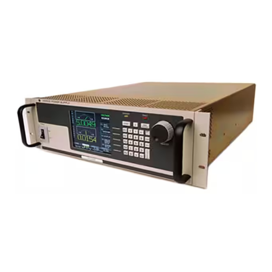
- Page 20 FIGURE 1-1. HIGH POWER BOP SERIES POWER SUPPLY BOP-1K 042722...
- Page 21 MEL and BOP 1KW-MGL series of 1000 Watt rack-mounted, 4-quadrant bipolar, programma- ble, voltage and current stabilized d-c power supplies manufactured by Kepco, Inc., Flushing, New York, U.S.A. This manual applies to both MGL models with a GPIB digital interface and MEL models with a LAN digital interface.
- Page 22 Closed Loop Gain Model Voltage Current O Max O Max Channel Channel 1000 WATT MODELS BOP 10-100MEL or MGL ±10V d-c ±100A d-c 10.0 BOP 20-50MEL or MGL ±20V d-c ±50A d-c BOP 36-28MEL or MGL ±36V d-c ±28A d-c BOP 50-20MEL or MGL ±50V d-c...
- Page 23 Input Installation Category II for TN or TT power systems Overvoltage Category II Output Installation Category II maximum 300V (500V for BOP 10-100MEL/ MGL) isolation voltage between each output Overvoltage Category II terminal and chassis ground. Pollution degree OUTPUT CHARACTERISTICS...
- Page 24 TABLE 1-2. BOP GENERAL SPECIFICATIONS (Continued) SPECIFICATION RATING/DESCRIPTION CONDITION OUTPUT CHARACTERISTICS (Continued) Analog Programming Voltage 0.01% of rating • Voltage and Current limit in Voltage Mode accuracy and Current and Voltage Limit in Current Current Limit 0.1% of rating Mode. Current 0.1% of rating •...
- Page 25 Series operation Master/slave Maximum of 2 identical units. Maximum of 2 identical units (6)(7) Parallel operation Master/slave (maximum of 3 for BOP 10-100MEL/MGL) Power-up Timing Series or parallel 15 sec. max. Time required for system to be able to systems respond to analog or digital control.
- Page 26 TABLE 1-2. BOP GENERAL SPECIFICATIONS (Continued) SPECIFICATION RATING/DESCRIPTION CONDITION PROGRAMMING CHARACTERISTICS Small signal voltage channel 1 KHz minimum Into nominal resistive load, 10% of rating Bandwidth for main current channel 800 Hz minimum channel (analog or Into short circuit, 10% of rating digital) ...
- Page 27 TABLE 1-2. BOP GENERAL SPECIFICATIONS (Continued) SPECIFICATION RATING/DESCRIPTION CONDITION PROGRAMMING CHARACTERISTICS (Continued) Trigger Port (See Table 2-4) Remote ON-OFF Operation of pin 2 is controlled by OUTP:CONT command (see Par. B.23). (pin 2): Settings are STANDBY, HIGH, LOW, OFF. Either OFF or STANDBY is required if using OUTP ON and OUTP OFF commands to control the output.
- Page 28 TABLE 1-2. BOP GENERAL SPECIFICATIONS (Continued) SPECIFICATION RATING/DESCRIPTION CONDITION FUNCTION GENERATOR CHARACTERISTICS (See PAR. 3.3.10) Digital control remote IEEE 488-2 (GPIB) or RS 232 SCPI (MGL models) remote LAN and RS 232 SCPI (MEL models) remote RS 485 (BITBUS) IEEE 1118, used for series and parallel config- urations local Panel mounted keypad...
- Page 29 TABLE 1-2. BOP GENERAL SPECIFICATIONS (Continued) SPECIFICATION RATING/DESCRIPTION CONDITION FUNCTION GENERATOR CHARACTERISTICS (Continued) Waveform Parameters Type: Voltage or Current • Type of waveform, voltage or current, can be selected only for a new waveform and Positive Protection Limit: consequently applies to all waveform seg- (Vd-c or Ad-c) ments.
- Page 30 TABLE 1-2. BOP GENERAL SPECIFICATIONS (Continued) SPECIFICATION RATING/DESCRIPTION CONDITION FUNCTION GENERATOR CHARACTERISTICS (Continued) LIST command characteristics for “string” type Maximum number of points Note: Dwell time list must match (balance) the waveform (Remote only) amplitude list. • For single (global) dwell time: 5900 (high resolution) •...
- Page 31 TABLE 1-2. BOP GENERAL SPECIFICATIONS (Continued) SPECIFICATION RATING/DESCRIPTION CONDITION FUNCTION GENERATOR CHARACTERISTICS (Continued) Waveform graphics displayed on LCD for both Local: The LCD represents the programming waveform graph of the main channel, Local and Remote operation voltage for voltage mode or current for current mode. •...
- Page 32 TABLE 1-2. BOP GENERAL SPECIFICATIONS (Continued) SPECIFICATION RATING/DESCRIPTION CONDITION FUNCTION GENERATOR CHARACTERISTICS (Continued) Amplitude Accuracy Main Channel Voltage 0.03% E O and Offset Current 0.1% I O Protection Limit. Current 0.5% I O Channel. Voltage 0.3% E O Distortion (THD-F, Total Harmonic Distortion 5% max.
- Page 33 Types Factory defaults: Main: DEFAULT, Password Main, Admin1, Admin2 Admin1: 0, Admin2: KEPCO Protection Choices Unprotected, Main, Admin1, Admin2 Password menu always protected by Admin2 Items Protected Interface, max/min , Load type, Test, Multiple unit configurations are protected by Calibration, Power-up, Keypad @ Admin2 password.
- Page 34 TABLE 1-2. BOP GENERAL SPECIFICATIONS (Continued) SPECIFICATION RATING/DESCRIPTION CONDITION GENERAL (ENVIRONMENTAL) CHARACTERISTICS Temperature operating 0 to +50 deg C Full rated load storage -20 to +85 deg C Cooling Two internal fans intake from the front, exhaust to the rear Humidity 0 to 95% RH non-condensing...
- Page 35 LOCAL CONTROL Either the front panel keypad or the adjust control can set and adjust output voltage and current under local control. The display provides a digital display of output voltage and current as well as a pictorial display of real-time analog voltage and current meters. The keypad includes five function keys which provide access to the menu-driven functions of the unit.
- Page 36 18.805 [477.63] 18.018 [457.64] 17.675 [448.93] 16.835 [427.60] OBROUND 0.25x0.453 (4 LOC.) 18.235 [463.16] 18.985 [482.21] FIGURE 1-2. 1000W BOP POWER SUPPLY, OUTLINE DRAWING (SHEET 1 OF 2) 1-16 BOP HIPWR 042722...
- Page 37 REAR VIEW REMOVE FEET FOR RACK MOUNTING. 22.000 [558.79] SLIDES TRAVEL DISTANCE: 23.000 [584.2] SEE NOTE 6. FIGURE 1-2. BOP POWER SUPPLY, OUTLINE DRAWING (SHEET 2 OF 2) 1-17 BOP HIPWR 042722...
- Page 38 FEATURES 1.6.1 DIGITAL CALIBRATION The BOP Power Supply contains no internal adjustments. Calibration is done entirely via the keypad or remotely via the GPIB (for MGL models), LAN (for MEL models) or RS 232 interface using digital entries and a calibrated DVM, a precision d-c reference voltage source and preci- sion shunt resistor.
- Page 39 TABLE 1-3. EQUIPMENT SUPPLIED ITEM FUNCTION PART NUMBER Source Power Entry mating connector Mates with source power entry connector 142-0381 (Kepco) (IEC 320 C19) PAR/SER CONTROL - IN Mates with PAR/SER CONTROL - IN port to allow 142-0488 (Kepco) mating connector...
- Page 40 BOP 10- KIT 219-0446 (3 in parallel for lel (increase output current) 100MEL/MGL models in parallel to produce a virtual BOP 10- BOP 10-100MEL/MGL only)) 200MEL/MGL. Interconnection Kit for multiple Cables required to connect multiple BOP models in series for...
- Page 41 Service must be referred to authorized personnel. Using the power supply in a manner not specified by Kepco. Inc. may impair the protection provided by the power supply. Observe all safety precautions noted throughout this manual (see listing on page D, preceding the Table of Contents).
- Page 42 NOTE 3. The concept of “box value” is illustrated above. It is an area around the origin, where the limits of the unit (voltage or current) cannot be programmed. This minimum (box) value for the positive limits or maxi- mum (box) value for the negative limits, is a model dependent constant of approximately 0.2% of the nominal values for voltage and current.
- Page 43 SECTION 2 - INSTALLATION UNPACKING AND INSPECTION This instrument has been thoroughly inspected and tested prior to packing and is ready for operation. After careful unpacking, inspect for shipping damage before attempting to operate. Perform the preliminary operational check as outlined in PAR. 2.3. If any indication of damage is found, file an immediate claim with the responsible transport service.
- Page 44 TABLE 2-1. REAR PANEL CONNECTOR FUNCTIONS NUMBER CONNECTOR/TERMINAL FUNCTION (FIGURE 2-1) (REFERENCE DESIGNATOR) IEEE 1118 (BITBUS) PORT Used for multiple identical BOP master/slave parallel, and series and series-parallel (connector A1J4) configurations (refer to PAR. 2.7.6.2, see Table 2-3). TRIGGER May be used to initiate BOP output. (See Table 2-4.) (connector A1J3) IEEE 488 (GPIB) PORT Installed on MGL models only.
- Page 45 VOLTAGE MONITOR FULL SCALE ADJ (A2A5R89) VOLTAGE MONITOR ZERO ADJ A2A5R85 CALIBRATION ADJUSTMENTS FIGURE 2-2. BOP1KW-MEL/MGL TOP COVER ACCESSIBLE COMPONENTS TABLE 2-2. CALIBRATION ADJUSTMENTS REFERENCE DESIGNATOR FUNCTION (FIGURE 2-2) A2A5R85 Voltage Monitor Zero Adjust (see PAR. 4.3.1, step 3) A2A5R89 Voltage Monitor Full Scale Adjust (see PAR.
- Page 46 TABLE 2-4. TRIGGER PORT PIN ASSIGNMENTS CONNECTOR SIGNAL NAME FUNCTION LOGIC GND Return for TRIGGER and OUTPUT ON-OFF signals. OUTPUT ON-OFF Operation of pin 2 is controlled from either the front panel (PAR. 3.3.6: LowPulse, HighIsOn, LowIsOn, HighIsOff, LowIsOff, OFF) or by OUTP:CONT command (PAR. B.23: LPLS, HON, LON, LOFF, HOFF, OFF).
- Page 47 TABLE 2-5. EXTERNAL PROTECTION CONNECTOR INPUT/OUTPUT PIN ASSIGNMENTS CONNECTOR SIGNAL NAME FUNCTION Cathode of LED optocoupler (through a 510 ohm resistor) which is used for external isolated shutdown. Anode of LED is connected to (A2A5J7) pin 2. A positive voltage (3.5 to 15V) at pin 2 (referenced to pin 1) shuts down the unit functionality.
- Page 48 TABLE 2-8. PARALLEL/SERIAL CONTROL IN PORT PIN ASSIGNMENTS CONNECTOR SIGNAL NAME FUNCTION SGND Local signal ground No connection S_IN_PARALLEL Input for programming output current of a parallel-connected slave. Pro- vided by master unit. Level: –10V to +10V controls the current between –I Onom to +I Onom . No connection PARALLEL/SERIAL No connection...
- Page 49 TABLE 2-11. ANALOG I/O PORT INPUT/OUTPUT PIN ASSIGNMENTS CONNECTOR SIGNAL NAME FUNCTION CAUTION: it is recommended that source power of external equipment connected to the Analog Port be applied through an isolating transformer To avoid ground loops or possible damage to the BOP due to incorrect equipment a-c wiring (e.g., defeating of ground connection).
- Page 50 TABLE 2-12. IEEE 488 PORT INPUT/OUTPUT PIN ASSIGNMENTS CONNECTOR SIGNAL NAME FUNCTION I/O Line I/O Line I/O Line I/O Line End or Identify Data Valid NRFD Not Ready for Data NDAC Not Data Accepted Interface Clear Service Request Attention IEEE 488 SHIELD Shield PORT...
- Page 51 4. Use the keypad to enter the rated maximum voltage of the power supply (e.g., enter 36 for a model BOP 36-28MEL/MGL) and press ENTER. If STANDBY indicator is lit, press STANDBY key. 5. Verify DVM voltage reading agrees with programmed voltage within 0.03% of rated maxi- mum voltage and agrees with displayed voltage on LCD within 0.05% of rated maximum voltage.
- Page 52 The user must provide a properly sized and rated mains lead (line cord) and service with a current rating compatible with the anticipated input current. Line cords available as accessories are listed in Table 1-4. Kepco recommends #12 AWG (2,0 mm diameter) for input line cord.
- Page 53 2.5.3.1 EARTH-GROUND CONFIGURATION When connecting a programming device to the BOP it is critical that only a single earth-ground point is connected. Figure 2-3 shows proper earth-ground connections for typical configurations, as well as an illustration of the consequences of multiple earth ground points. IF THE FOLLOW- ING CAUTION IS NOT OBSERVED, ANY DAMAGE TO THE UNIT IS THE USER’S RESPON- SIBILITY AND IS NOT COVERED UNDER THE WARRANTY.
- Page 54 ANALOG I/O PORT BOP 1KW PROGRAMMING DEVICE LOAD SGND ANALOG I/O PORT BOP 1KW PROGRAMMING DEVICE LOAD CORRECT! SGND ANALOG I/O PORT BOP 1KW PROGRAMMING DEVICE LOAD SGND ANALOG I/O PORT BOP 1KW With two earth-ground points as PROGRAMMING DEVICE shown, a ground loop allows return current to flow through the internal LOAD...
- Page 55 2.5.5 LOAD CONNECTION - GENERAL Load connections require wires that are properly rated for the nominal output current of the unit. Load connections to the BOP power supply are achieved via the OUTPUT and COMMON bus bar-type terminals located on the rear panel. A barrier strip is provided at the rear panel for con- nection of the sense wires to the load (for remote sensing or multiple unit applications).
- Page 56 SETTING UP THE UNIT The following paragraphs describe the connections and initial BOP setup needed to operate in the desired mode. 2.7.1 CONSIDER THE LOAD TYPE The BOP can be configured to respond differently to the Output OFF command, depending on whether the load is defined as Active, Resistive or Battery.
- Page 57 N / C FIGURE 2-5. LOAD CONNECTIONS, REMOTE SENSING 2.7.3 SETUP FOR FAIL SAFE/INTERLOCK PROTECTION WARNING: This feature requires disassembly and modification of the unit and implementation is permitted only by authorized service personnel. To enable the Fail Safe/Interlock Protection feature, refer to the Service Manual for component locations and remove the cover of the unit.
- Page 58 FIGURE 2-6. FAIL SAFE FEATURE, SIMPLIFIED SCHEMATIC DIAGRAM 2.7.4 SETUP FOR REMOTE OPERATION VIA GPIB (MGL MODELS ONLY) With all power off, connect the load to the BOP using either local or remote sensing. If units are to be connected in series or parallel, refer to PAR. 2.7.6.2. Connect the GPIB connector to the GPIB port (see Figure 2-1 and Table 2-1).
- Page 59 The PSfind utility can be downloaded from the Kepco web site at www.kepcopower.com/drivers/drivers-dl3.htm#bop1k This utility finds all operational Kepco power supplies connected to the LAN and then shows the MAC and IP addresses of the models found. To run the utility from your PC download the psfind.zip file to your computer. Extract psfind.exe from the zip file to a location of your choice, then double-click psfind.exe to run the application.
- Page 60 FIGURE 2-8. DISCOVERY USING SAFARI BROWSER WITH BONJOUR INSTALLED 2.7.6.3 LXI DISCOVERY Figure 2-9 shows a Kepco BOP 10-100MEL power supply found on the LAN using the LXI Dis- covery Tool. FIGURE 2-9. TYPICAL SCREEN USING LXI DISCOVERY TOOL 2-18...
- Page 61 Although most current browsers will work, Kepco recommends the following as fully supported: Safari, IE 8.0 and higher and Firefox 1.0 and higher. Popup blocking must be disabled and Javascript must be enabled for proper operation.
- Page 62 2.7.6.5 LAN CONFIGURATION USING WEB INTERFACE From the Web Interface Home Page (Figure 2-10) click on CONFIGURE LAN at the left to view the LAN Configuration page (Figure 2-11). The parameters that can be configured from this page are Host Name (DHCP), Description, IP Address, Subnet Mask address, Default Gateway Address, and DNS Server Address.
- Page 63 N = number of units in parallel. Similarly, up to two identical units can be connected tion) in series to increase the voltage (except up to three BOP 10-100MEL/MGL units may be con- nected in series): E where N...
- Page 64 2.8.1 MULTIPLE UNIT CONNECTIONS Before connecting the units in parallel or in series, configure each for master or slave (see PAR. 2.8.4), and save for power up. Then turn off the units and proceed with the parallel or series con- nection.
- Page 65 FIGURE 2-12. PARALLEL CONFIGURATION, LOCAL SENSING, TYPICAL (THREE IN PARALLEL FOR BOP 10-100MEL/MGL ONLY) 2-23 BOP HIPWR 042722...
- Page 66 FIGURE 2-13. PARALLEL CONFIGURATION, REMOTE SENSING, TYPICAL (THREE IN PARALLEL FOR BOP 10-100MEL/MGL ONLY) 2-24 BOP HIPWR 042722...
- Page 67 N / C N / C FIGURE 2-14. SERIES CONFIGURATION, LOCAL SENSING, TYPICAL 2-25 BOP HIPWR 042722...
- Page 68 N / C N / C FIGURE 2-15. SERIES CONFIGURATION, REMOTE SENSING, TYPICAL 2-26 BOP HIPWR 042722...
- Page 69 2.8.2 MULTIPLE UNIT PROTECTION For multiple unit configurations it is necessary to configure the protection so that a fault will shut down all the interconnected power supplies. Figure 2-16 is a simplified diagram showing typical interconnections for master/slave configurations. 2.8.3 MULTIPLE UNIT SOURCE POWER When multiple units are connected in series or parallel, the individual power supplies of the sys- tem may be connected to different phases of a 3-phase a-c power source.
- Page 70 2.8.4 CONFIGURING PARALLEL OR SERIES COMBINATIONS NOTE: Successfully configuring the unit from Standalone to Parallel or Series will reset all NVRAM variables to factory defaults and delete all saved setups and saved wave- forms. 1. To configure a unit to be designated as a slave proceed as follows: a.
- Page 71 = slave number + 4. So for example an *IDN? query to slave 1 will have #5 appended to the end of the response: KEPCO,BOP 20-50 AUG 10 2016,A123456,6.43#5 2. Repeat step 1 as necessary to configure all slaves, but at step d highlight applicable SLAVE # as appropriate.
- Page 72 stage will advance to the identification stage when slave status is no longer “No Answer” and is either “Faulted”, 'Mode Error” or “Unit Error, and the protection line is valid. If the protection stage fails (indicated by an external fault indication), possible causes are a) an external device (if used) connected to the protection circuits to initiate master shutdown, or b) improperly installed protection cables.
- Page 73 If all the slaves are recognized as ready, after no longer than 15 seconds maximum the master LCD reverts to the Power On Default screen (see Figure 2-18). The slaves display the Slave Power On Default screen (see Figure 2-19), except the unit will be in Current Mode for parallel configurations and Voltage mode for series configurations and the message will indicate the unit is operating as a slave.
- Page 74 example, for a parallel combination the values for +Current Max, –Current Min and ±Cur- rent Protect Max/Min now reflect the total current of the parallel combination. Voltage val- ues and limits reflect a series combination. NOTE: If desired, these limits may be lowered as described for a standalone unit (see PAR.
- Page 75 2.8.6 OPERATING INSTRUCTIONS FOR MULTIPLE UNIT COMBINATIONS 1. Apply power to the multiple units. If the master is in STANDBY, depress STANDBY key on the master to apply power to the output terminals. (To power down the combination, first press STANDBY key on the master to disable the output, then turn off the slaves, followed by the master.
- Page 77 SCPI commands which afford full functionality of the BOP (see PAR. 3.6, Appendix A and Appendix B) or 2) CIIL commands (for compatibility with older Kepco products). MGL model operation in remote mode can be simplified by the use of the VISA driver (see PAR.
- Page 78 FIGURE 3-1. BOP SERIES FRONT PANEL TABLE 3-1. FRONT PANEL CONTROLS AND INDICATORS NUMBER CONTROL/INDICATOR FUNCTION (FIGURE 3-1) POWER ON/OFF Applies source power to unit circuit breaker A7CB1 Displays output voltage and current as well as information in response to Alphanumeric/graphic Display ( keypad and ADJUST control entries.
- Page 79 3.2.1 KEYPAD DESCRIPTION (SEE FIGURE 3-2) The front panel keypad is comprised of 27 keys, eleven for 10 digits (0 - 9) plus decimal point, five dedicated to software functions ( ) indicated by the display, four direction keys ) that work with the display to select a parameter/field and highlight a numerical digit, and seven dedicated function keys (STANDBY, MODE, RESET, CLEAR, +/–, ENTER and HELP) that are defined in Table 3-2.
- Page 80 3.2.2 LCD AND POWER-UP SCREEN DESCRIPTION The LCD display is a 320 x 240 pixel color window that displays various menus depending on the state of the power supply and operator input. Upon turning the unit on, the start-up screen (Figure 3-3) is displayed briefly, showing the firm- ware versions of the BOP processors and the results of the start-up self test.
- Page 81 ANALOG VOLTMETER OPERATING VOLTAGE INFO SOURCE DIGITAL VOLTMETER 0.0000 ANALOG AMMETER SOFTWARE FUNCTION DIGITAL AMMETER KEYS 0.0402 HIGHLIGHT TO CHANGE LOCAL/REMOTE STATUS VOLTAGE 0000 ACTIVE SETTINGS LAN OK MESSAGES NOTE: WHEN SET TO BIPOLAR, ONLY ONE PROTECTION FIELD IS DISPLAYED. WHEN SET TO INDEPENDENT, TWO PROTECTION FIELDS ARE DISPLAYED AS SHOWN HERE.
- Page 82 When in Current mode, the power supply will (within the configured and rated limits) provide the programmed output current. Mode displayed at the upper right is CURRENT. Voltage is deter- mined by the load, and cannot exceed the Voltage Protect limits. Either SOURCE or SINK is displayed below the mode of operation.
- Page 83 When the power supply is turned on, it performs a brief self-test that includes testing the three processors (analog, interface and display), then displays the power-up screen (see Figure 3-4 or 3-5). If an error is detected, the FAULT indicator will light, information about the error will be briefly displayed on the LCD.
- Page 84 Power-up Screen (Power up menu) • - Save/Recall • • Saved Setups (Figure 3-10): Recall one of 99 saved setups. • • • Saved Setup Details (Table 3-9): Mode (voltage/current/External), main channel reference (inter- nal/external/external reference level) and setting, Protection Type (internal/external/LesserLimit) and setting(s), output status (on/off) •...
- Page 85 To change any password you must enter the Admin 2 password to access the Password Menu. The unit is shipped with the Admin 2 password set to “KEPCO,” the Main Unit password set to ”DEFAULT,” and the Admin 1 password is not assigned. To change the password or to protect one of the protected menus, proceed as follows: 1.
- Page 86 2. Enter the Admin 2 password (see PAR. 3.2.4.3 for details), then press to verify. The Password Protection menu (see Figure 3-6) is now displayed. 3. To change a password, highlight the Main Unit, Admin 1 or Admin 2 password and press to modify.
- Page 87 VOLTAGE CURRENT VOLTAGE 0.0000 0.0000 SOURCE Admin 2 Admin 2 FIGURE 3-6. PASSWORD PROTECTION MENU, FACTORY DEFAULTS 3.2.5 DISPLAY SETTINGS (OPERATOR CONVENIENCE) MENU From the power-up screen (Figure 3-4), pressing opens the Display Settings Menu (see Fig- ure 3-7 and Table 3-3). The functions listed can be modified using the techniques described in PAR.3.2.4).
- Page 88 3.2.5.1 DISPLAYING METERS OR GRAPH (TIME LINE) The top screen can be configured to either display graphical analog meters (Figure 3-4) show- ing a coarse representation of voltage and current in addition to the digital readout, or a graphi- cal time line (Figure 3-5). The graphical time line is not an oscilloscope type display. Instead, it samples the output and refreshes the screen at a specified interval: 75, 30, 15, 7.5, 3.8, 1.5, 0.8, 0.3, or 0.15 Seconds.
- Page 89 TABLE 3-3. DISPLAY SETTINGS (OPERATOR CONVENIENCE) MENU CHOICES SETTING (BOLD = Factory FUNCTION Default) NOTE: To save any of the functions listed below for power-up it is necessary to first change SAVE DISPLAY CHG at the password setup (see PAR. 3.2.4.2and Figure 3-6) from DISABLE to ENABLE. Graphic Display Meters Meters - Output voltage and current are displayed on representations of analog...
- Page 90 LOCAL MODE OPERATION Local operation of the BOP power supply can be accomplished from the front panel via the 27 key keypad, and the ADJUST knob. All indications are provided by the 4.7-inch color graphical display (LCD). 3.3.1 SETTING LOCAL MODE When the power supply is turned on, it is automatically set to Local mode.
- Page 91 3.3.3 PROGRAMMING VOLTAGE OR CURRENT AND ASSOCIATED PROTECT LIMITS From the power-up screen the settable voltage/current parameters are displayed at the bottom of the LCD above the HELP message (see Figure 3-4). Use to highlight the main or protect channel. (For BOP protect limits refer to PAR. 3.3.4.2 and for external limits see PAR. 3.3.4.3.) 1.
- Page 92 TABLE 3-4. VOLTAGE AND CURRENT PARAMETER DEFINITIONS To modify refer to PAR. Term Definition Local Remote The nominal (rated) output voltage of the unit determined by model; e.g. for Onom –E a BOP 36-28MEL/MGL, ±E is 36V. Onom Onom The nominal (rated) output current of the unit determined by model; e.g. for Onom –I a BOP 36-28MEL/MGL, ±I...
- Page 93 3.3.3.1 SELECTING BIPOLAR/INDEPENDENT PROTECTION LIMITS The BOP can be configured to allow the protection limits to be displayed and changed from the front panel as either a single value that applies to both protection channels or as individual set- tings for positive and negative protection limits. Selecting Independent protection limits means that the positive and negative limits are displayed (and can be modified) independently.
- Page 94 Selection of Bipolar does not immediately change the protect limit values; it changes how the protect settings are displayed and set from the power-up screen. So if maximum/minimum pro- tection limits were set to different values, (e.g, for BOP 36-28MEL/MGL, current mode, no load, +V Protect Max = 25V and –V Protect Min = 7V) when Bipolar is selected, the previous protec- tion values (+25, –7) will remain in place until a new value is entered in the Voltage Protection field.
- Page 95 The internal parameters +Current Protect Min and –Current Protect Max are displayed to com- pletely define the permissible window when operating in Voltage mode. Similarly, +Voltage Pro- tect Min, and –Voltage Protect Max are displayed to completely define the permissible window for voltage when operating in Current mode.
- Page 96 3.3.4.1 CHANGING MAXIMUM ACCEPTED VOLTAGE OR CURRENT (MAIN CHANNEL SOFT- WARE LIMITS) The software limits for the main channels (+Voltage Max, –Voltage Min, +Current Max and –Current Min) are the maximum (positive) and minimum (Maximum negative) values allow- able for voltage and current. The default software limits are determined by the model: the nom- inal (rated) values for voltage and current (e.g., 36V and 28A for the BOP 36-28MEL/MGL).
- Page 97 VOLTAGE CURRENT VOLTAGE 0.0000 0.0000 SOURCE VOLTAGE MODE +Voltage Max.: 10.0 -Voltage Min.: 10.0 +C Protect Max.: 75.8 +C Protect Min.: 0.02126 -C Protect Min.: 0.02128 -C Protect Max.: 75.8 CURRENT MODE +Current Max.: 75.0 -Current Min.: 75.0 +V Protect Max.: 10.1 +V Protect Min.: 0.15584...
- Page 98 3.3.4.3 EXTERNAL LIMITS These limits are external analog signals which are converted within the BOP to digital signals that program the protection channels only: current protect in voltage mode and voltage protect in current mode. The range of each analog input signal is +1V to +10V, corresponding to a range for clamping the output between minimum, 10% of nominal (positive and negative), to +max/–min of nominal rating.
- Page 99 TABLE 3-6. POWER SUPPLY BEHAVIOR WHEN OUTPUT IS SET TO OFF LOAD TYPE If unit was in Voltage Mode when output OFF If unit was in Current Mode when output OFF SETTING command issued. command issued. • Unit remains in voltage mode. •...
- Page 100 WARNING: Accessing the BOP after the output is disabled in BATTERY mode is hazardous because (1) high current arcing is possible and (2) either the external battery voltage, or the voltage (±Volt- age Protection max) on the BOP output terminals may be dan- gerous.
- Page 101 3.3.7.1.1 BATTERY OPERATIONS USING VOLTAGE MODE Using voltage mode with remote sensing connections provides more accurate voltage control of the battery, avoiding the effects of both parasitic voltage drops on the connection wiring and the battery’s internal resistance. The BOP output voltage is set to the desired battery voltage and current limit is set to the required charging current value.
- Page 102 BOP current setpoint. As previously described, if not monitored and the process stopped, the discharge will completely deplete the battery. If current mode is needed, Kepco can modify the unit to establish the voltage limit feedback loop to use the Sense terminals, rather than the Monitor terminals. The modified unit behaves similar to that described for voltage mode except that voltage accuracy is 12-bit/ 0.3%, versus 14-bit/...
- Page 103 TABLE 3-7. POWER UP SETTINGS MENU CHOICES PARAMETER FUNCTION (BOLD = Factory Default) NOTE: DEFAULT values for empty cells are the settings of the unit at the time the save/recall menu is entered. Mode of Operation Voltage Voltage - Selects voltage mode. Voltage value determined by SETTING. Current Current - Selects current mode.
- Page 104 TABLE 3-8. EXAMPLES SHOWING HOW POWER-UP SETTINGS FUNCTION Main Power-up condition (output set to ON) Protection Mode of Channel (All referenced pins located on Analog I/O Port Operation see PAR. 3.4 and Figure 2-1) Reference Setting Type Levels Unit powers up in voltage mode, +5V, ±current protection set to Voltage: 10 25A.
- Page 105 3.3.9.1 UNDERSTANDING ABBREVIATIONS USED FOR SAVED SETTINGS The parameters listed in Table 3-9 are displayed, followed by a listing of the first 20 memory locations, displayed in two rows of ten. Use keys to display additional columns or navigate to the desired location. Locations that are not empty show an abbreviated representation of the saved settings.
- Page 106 TABLE 3-9. SAVE/RECALL MENU CHOICES PARAMETER FUNCTION (BOLD = Factory Default) NOTE: DEFAULT values for empty cells are the settings of the unit at the time the save/recall menu is entered. Mode of Voltage Voltage - Selects voltage mode. Voltage value determined by SETTING. Operation Current Current - Selects current mode.
- Page 107 VOLTAGE CURRENT VOLTAGE 0.0000 0.0000 SOURCE FIGURE 3-10. SAVED SETUPS MENU 2. Use the keys to highlight the desired memory location; To erase a highlighted memory location, press . The list will show erased locations as Empty. 3. Press to see the details stored in the highlighted location. 4.
- Page 108 Waveforms may be programmed, stored and executed using LIST commands found in Appen- dix B. The interactive demo program portion of the Labview G driver for BOP 1KW (download- able from the Kepco web site at http://www.kepcopower.com/drivers/drivers-dl3.htm#bop1k) provides examples of generating waveforms remotely. Documentation for the demo program examples can be found in the Labview, VXI Plug&play Driver Manual for BOP-BIT available for...
- Page 109 A waveform is comprised of at least one, or as many as 10 segments. Each segment has an individually specified value for Type, Frequency or Period, Amplitude, Offset, Start angle, Stop angle, and Initial/Repeat; see Table 3-12 for details. To view a previously saved waveform Refer to PAR.
- Page 110 TABLE 3-10. SINE, TRIANGLE AND RAMP WAVEFORM FREQUENCY VS. POINTS Frequency Frequency Total Points Total Points (See Notes 1, 2, and 3) (See Notes 1, 2, and 3) per segment per segment From From 0.01Hz 2.7Hz 3840 55.5Hz 66.5Hz 2.71Hz 3.6Hz 2880 66.6Hz...
- Page 111 3.3.10.5 VIEWING STORED WAVEFORMS After observing the precautions of PAR. 3.3.10.1, press from the power-up screen to access the Saved Waveforms screen (Figure 3-11). Use or the encoder to highlight the name of a previously saved waveform, then press to view the Waveform Settings screen (see Fig- ure 3-12).
- Page 112 VOLTAGE CURRENT VOLTAGE 0.0000 0.0000 SOURCE New Waveform Menu Waveform Name: Voltage Mode of Operation: Number of Cycles: 38.400 Posititve Protect: 126.300 Negative Protect: First Segment Sine Type: 1.0000 Frequency (Hz): 200.0000 PtoP Amplitude 0.0000 Offset: FIGURE 3-13. NEW WAVEFORM MENU 2.
- Page 113 TABLE 3-12. WAVEFORM SEGMENT DETAILS MENU SETTING CHOICES FUNCTION Type Square Square - Square wave, bipolar, starts with positive excursion (see Note 1). + Ramp + Ramp - Increasing ramp, bipolar (see Note 1). - Ramp - Ramp - Decreasing ramp, bipolar (see Note 1). Triangle Triangle - bipolar, starts with positive excursion, start/stop angle may be user controlled (see Note 1).
- Page 114 TABLE 3-12. WAVEFORM SEGMENT DETAILS MENU (CONTINUED) SETTING CHOICES FUNCTION Start Angle xxx x The point at which the sine or triangle waveform segment starts. Values from 0.0° to (Sine or Triangle only) (degrees) 360.0° are acceptable. Default is 0.0°. Stop Angle xxx x The point at which the sine or triangle waveform segment stops.
- Page 115 TABLE 3-13. NEW WAVEFORM SETTINGS MENU (CONTINUED) SETTING CHOICES FUNCTION Frequency (Hz) Square wave: 0.02 to 1000 Hz (0.02 to 1.35Hz if ZINC or ZDEC used) Ramp: 0.02 to 532 Hz (0.02 to 2.7Hz if ZINC or ZDEC used) Sine or Triangle:0.001 to 443 Hz (0.001 to 1.35Hz if ZINC or ZDEC used) Level or Slope: Period in Seconds.
- Page 116 Stop & End Cycle - Press to select Stop & End Cycle. When waveform is stopped (either count complete or pressed), waveform runs through full cycle. The output stops at the last generated value of the waveform (e.g., for a sinewave segment of 0° to 270°, 10V amplitude, 0V offset, when is pressed the output will end up at -10V).
- Page 117 3.3.10.9 USING SEGMENTS TO BUILD A WAVEFORM The following steps provide detailed instructions to illustrate how a complex waveform, illus- trated in Figure 3-14, may be created by building segments. Refer to PAR. 3.2.4 for details on changing parameters if needed. 1.
- Page 118 3. From the Waveform Settings screen, highlight segment NEG RAMP 50.0HZ 4.00 R and press to insert a new segment. Use to modify the following settings of the new seg- ment. For each parameter, use to save the setting. Type Level Period (Sec) 0.002...
- Page 119 6. From the Waveform Settings screen, highlight End of Segments and press to insert the next segment. Use to modify the following settings for the next segment. For each parameter, use to save the setting Type Sine Frequency (Hz) Amplitude (p-p) Offset Start angle Stop angle...
- Page 120 3.3.12 OPERATOR TESTING The Test System submenu is entered by pressing from the power-up screen, then highlight Revision/Test and press . Upon power-up all tests are flagged as Untested. Table 3-14 lists the tests that can be run. Highlight the choice and press to run the selected test.
- Page 121 3.3.13 ERROR MESSAGE EXPLANATIONS When a key press is not accepted, an error message is displayed at the bottom of the screen. Although recovery from most operator errors is obvious and simple, Table 3-15 lists all the error messages along with associated explanations as to why they occurred. TABLE 3-15.
- Page 122 Noise sup- pression is accomplished by connecting a 100F ceramic capacitor, rated at 50V or 100V (e.g., Kepco P/N 117-1241), between GND and COM S terminals (see Figure 2-4 for local sensing or Figure 2-5 for remote sensing).
- Page 123 3.4.2.1 REMOTE SHUTDOWN A standalone unit can be shut down using a remote signal applied to the PROTECTION EXT. PORT as shown in Figure 3-15 or 3-16 or by a remote control applied at PAR/SER PROTECT PORT IN as shown in Figure 3-17. A multiple unit configuration (parallel, series or series-paral- lel) can be disabled by applying a remote signal to the master PROTECTION EXT PORT as shown in Figure 3-15 or by applying a remote control to PAR/SER PROTECT PORT IN as shown in Figure 3-17.
- Page 124 CAUTION: This configuration must be enabled before use. See PAR. 2.7.3 for details. FIGURE 3-17. REMOTE SHUTDOWN COMBINED WITH CABLE-DISCONNECT SHUTDOWN, FOR STANDALONE OR MULTIPLE UNITS, FIGURE 3-18. REMOTE SHUTDOWN USING INTERNAL POWER, FOR MULTIPLE UNITS, 3.4.2.2 REMOTE STANDBY A standalone unit or a multiple unit configuration (parallel, series or series-parallel) can be set to STANDBY status by applying a remote signal to the TRIGGER PORT as shown in Figure 3-19.
- Page 125 3.4.3 VOLTAGE/CURRENT MODE CONTROL The mode of operation, voltage or current, can be programmed externally by applying a signal at pin 2, referenced to pin 9, of the Analog I/O port. Applying a TTL logic 1 (or open circuit) pro- grams the unit to voltage mode.
- Page 126 3.4.4.1 FIXED GAIN USING EXTERNAL REFERENCE CONTROL The main channel of the BOP, either voltage in voltage mode or current in current mode, can be controlled by an external reference voltage, 0 to ±10V applied at pin 11, referenced to pin 10, of the Analog I/O port.
- Page 127 3.4.4.2 VARIABLE GAIN USING EXTERNAL REFERENCE LEVEL The BOP can function as a variable gain power amplifier for both voltage and current modes, similar to the fixed (inherent or nominal) gain amplifier as described in PAR. 3.4.4.1. The user can determine a new (lower) full scale output value for the ±10V reference level (applied at pin 11, referenced to pin 10, of the Analog I/O port) by configuring the Reference input as follows: 1.
- Page 128 3.4.5 EXTERNAL PROTECTION LIMITS When Protect Limit on the Reference Menu is set to External, the protect limits are determined by four analog signals referenced to Ground (pin 12) which are applied to the Analog I/O Port (see Table 2-11). To be functional this feature must first be configured either from the front panel, or by sending either CURR:MODE:PROT EXT (see PAR.
- Page 129 3.4.5.1 USING BOTH LOCAL/DIGITAL AND EXTERNAL PROTECTION LIMITS When Protect Limit on the Reference Menu is set to Lesser Limit, the protect limits are automat- ically selected from either 1) the external analog voltage applied to the Analog I/O port (see PAR.
- Page 130 3.5.1.1 MEASUREMENT CAPABILITIES The default measurement functionality continually samples the voltage and current and saves the samples in an array. Every 16 sample pairs the sample is averaged and compared to the previous measurement sample. If the new sample is more than a few LSBs different from the previous one, the new sample and the next sample are provided to both the SCPI processor and the front panel display.
- Page 131 3.5.2.1 PROGRAMMING VOLTAGE/CURRENT LIMIT AND CURRENT/VOLTAGE LIMIT Kepco's auto-crossover digital supplies can operate in either voltage mode with current limit, or current mode with voltage limit. The operating mode is determined by the voltage and current commands received, as well as the load. Each time voltage and current commands are received, the unit must evaluate the commands and the load conditions to determine the neces- sary operating mode.
- Page 132 1. Minimize programmed mode (voltage or current) changes. Unless absolutely required by the test parameters, allow the power supply to automatically switch modes as determined by the load. This will improve response time and reduce undesirable transients. 2. Once the mode (voltage or current) is programmed, program the active parameter to zero and the complementary limit parameter to the maximum anticipated for application.
- Page 133 For commands not marked with (**) failure to provide a delay of about 1 minute can result in: • Commands that are not processed, • The following command may be received in error, causing an error in the transmission, • Unit lock-up requiring power cycling of the unit. If working via the GPIB bus, sending Interface Clear and Device Clear followed by *RST will unlock the unit.
- Page 134 Kepco’s BIT cards, however there are differences in operation (see PAR. 3.5.3.5 and 3.5.3.6. The SYSTem:SET and SYSTem:LANGuage commands can be used to configure the BOP to operate in a manner similar to earlier models of Kepco’s 100W, 200W and 400W BOP power supplies. 3.5.3.1 DETERMINING WHETHER *RST COMMAND SETS THE OUTPUT OFF OR ON When operating in remote mode, the Reset command *RST (see PAR.
- Page 135 TABLE 3-17. INTERFACE SETTINGS MENU (CONTINUED) CHOICES SETTING FUNCTION (BOLD = Factory Default) Baud Rate Selects RS 232 serial port baud rate. Baud Rate is not changed when 9600 factory defaults are restored by pressing 19200 38400 XON / XOFF ENABLE ENABLE - Allows BOP to control when data is received (see PAR.
- Page 136 3.5.3.3 RS 232 SERIAL PORT SETUP Paragraphs 3.5.3.3.1 through 3.5.3.3.3 below describe the setup required for the BOP to com- municate via the RS 232C Serial bus using SCPI commands. Table 3-17 shows the menu for Serial interface settings. 3.5.3.3.1 SELECT BAUD RATE To change the Baud Rate configuration press from the power-up screen, then highlight Interface Settings and press...
- Page 137 TABLE 3-18. LAN INTERFACE SETTINGS MENU CHOICES SETTING FUNCTION (BOLD = Factory Default) Read-only display of MAC address for the unit. IP Address 0.0.0.0 Allows IP address to be set manually if both DHCP and AUTO IP are set to OFF. If either DHCP or AUTO IP are set to ON, provides read- only display of automatically generated IP address.
- Page 138 3.5.3.4.2 CHANGE IP ADDRESS MASK. To set the Address Mask manually, first set both DHCP (see PAR. 3.5.3.4.4) and AUTO IP (see PAR. 3.5.3.4.3) to OFF. From the LAN Interface Settings submenu highlight Address Mask and press . Then enter the address mask as described above for IP Address (see PAR. 3.5.3.4.1).
- Page 139 3.5.3.6 BIT 4886 COMPATIBILITY Although the SYST:SET command can be used to configure the BOP 1KW the same way the BIT 4886 is configured, the BOP 1KW is not directly compatible with the older linear BOP mod- els using a BIT 4886 for digital remote control. There are differences in behavior between the two in handling LIST commands, status reporting and trigger operation as described below.
- Page 140 TABLE 3-19. IEEE 488 (GPIB) BUS INTERFACE FUNCTIONS SUBSET FUNCTION COMMENTS SYMBOL Source Handshake Complete Capability (Interface can receive multiline messages) Acceptor Handshake Complete Capability (Interface can receive multiline messages) Talker Basic talker, serial poll, unaddress if MLA (My Listen Address) (one-byte address) Listener Basic listener, unaddress if MTA (My Talk Address) (one-byte address).
- Page 141 Status Byte Sent 3.5.5 BOP VISA INSTRUMENT DRIVER The VISA instrument driver for the BOP power supply, available for download at www.kepco- power.com/drivers.htm, simplifies programming with a VISA compatible GPIB controller. Included are: • source code (C) for all VISA functions (kp_bophi.c) •...
- Page 142 3.5.6.1 SERIAL INTERFACE The serial interface behaves like the GPIB interface in that the command is parsed after receiv- ing a control character of either a Line Feed or Carriage Return. The serial interface supports six special control characters. The four special control characters are: Escape (1B Causes the input buffer to be cleared.
- Page 143 characters are received, the initial characters are lost; DSR stays low and XOFF is not transmit- ted to the host until all data in the buffer is processed. If a line terminator is received during the buffering period, as soon as the first command string is complete, the next command string is processed.
- Page 144 The XOFF character stops data transmission if XON/XOFF flow control is enabled (see PAR. 3.5.3.3.2 and Table 3-17). The CAN character resets the receive and transmit pointers and queues. CAUTION: When the serial port has received an XOFF, the error message “-400, Query Error”...
- Page 145 If each of the above steps is completed successfully, the problem lies in the computer hard- ware and/or software. Refer to the Product Support area of the Kepco website for additional information regarding RS 232 communications problems: www.kepcopower.com/support.
- Page 146 These default setting can be restored using the LAN Reset button (see Figure 2-1) or configured as desired from the web interface (see PAR. 3.5.7.2). If the LAN connection is active when the LAN Reset button is pressed, the default values are as shown above, except that IP, MASK, GATE and DNS addresses are retrieved from the LAN or router and may differ from values shown 3.5.7.2...
- Page 147 This feature allows for easy discovery through the MDNS or Bonjour common naming system. When using the unit with Kepco drivers, the user must add a 0 (or other number) to the VISA address string to represent the actual TCPIP connection on the computer. For example TCPIP0::192.168.1.111::5025::SOCKET is the correct VISA resource string to use with Kepco...
- Page 148 FIGURE 3-22. WEB INTERFACE HOME PAGE (UNIT DESCRIPTION) 3.5.7.5 LAN CONFIGURATION USING WEB INTERFACE From the Web Interface Home Page (Figure 3-22) click on CONFIGURE LAN at the left to view the LAN Configuration page (Figure 3-23). The parameters that can be configured from this page are Host Name (DHCP), Description, IP Address, Subnet Mask address, Default Gateway Address, and DNS Server Address.
- Page 149 FIGURE 3-23. WEB INTERFACE CONFIGURE LAN PAGE The factory default is that passwords are not needed to access password-protected areas and none of the three passwords are established. To set a password for the first time, leave the CURRENT field blank, enter the new password in the NEW and REPEAT fields, then click SUB- MIT.
- Page 150 and 3) whether the output is on or off. An ON/OFF button can be clicked to turn the output on or off. The MODE button allows the user to change the BOP 1KW-MEL operating mode (voltage or current). A small white “~” to the left of the voltage display flashes to indicate the web page is communi- cating with the unit.
- Page 151 The Ref Input button allows selection of either an INTERNAL or EXTERNAL reference level to control the main channel output. When Ref Input is set to EXTERNAL, the unit uses an external reference to change the main channel, whether voltage or current. For example, in voltage mode a ±10V reference applied to analog port pin 11 (referenced to pin 10) produces ±E (rated).
- Page 152 3. Enter Wave Frequency (Hz). 4. Click Generate Wave Segment button to add a segment (the information displayed in the Voltage or Current dialog boxes). Repeat steps 1 through 3 above to add additional seg- ments as desired. 5. When all the segments have been completed, enter the Loop number to specify how many times the waveform will run.
- Page 153 3.6.1 SCPI MESSAGES There are two kinds of SCPI messages: program messages from controller to power supply, and response messages from the power supply to the controller. Program messages consist of one or more properly formatted commands/queries and instruct the power supply to perform an action;...
- Page 154 An optional offset can be added to the command to cause the BOP to generate a non-centered waveform. For example, a 5 volt 400 Hertz sine wave may be centered at -3 volts. The list sub- system has controls the allow the user to modify the unit's behavior to generate parts of wave- forms and to used specific dwell times as appropriate.
- Page 155 ROOT : (colon) [SOURce:] subsystem LIST subsystem [SOURce:] [SOURce:] LIST CURRent VOLTage :CLEar [:LEVel] [:LEVel] :COUNt val [:IMMediate] [:IMMediate] :COUNt? [:AMPLitude] val [:AMPLitude] val :COUNt:SKIP int [:AMPLitude]? MIN, MAX [:AMPLitude]? MIN, MAX :COUNt:SKIP? :TRIGgered :TRIGgered :CURRent val,val [:AMPLitude] val [:AMPLitude] val APPLy type,val1,val2,val3 [:AMPLitude]? [:AMPLitude]?
- Page 156 3.6.3.6 MEMORY SUBSYSTEM This subsystem controls the Flash Memory used by the BOP microprocessors and is used for storing setup parameters and for storing a list for later recall and execution. The unit’s configuration, voltage and current, saved setups (*SAV and *RCL command) and Cal- ibration values are stored in Flash Memory.
- Page 157 3.6.3.10 CALIBRATE SUBSYSTEM The BOP series of power supplies support software calibration. A full calibration consist of a voltage calibration and a current calibration. These calibration procedures include steps that prepare the unit for series or parallel operation. Both voltage and current calibrations consist of a zero (performed on the main channels only) and positive and negative full scale calibrations with both internal and external references.
- Page 158 3-28 illustrates the message structure, showing how message units are combined. The follow- ing subparagraphs explain each component of the message structure. NOTE: An alternative to using the message structure for multiple messages defined in the fol- lowing paragraphs is to send each command as a separate line. In this case each com- mand must use the full syntax shown in Appendix B.
- Page 159 exceptions to the rules, where only the long form is accepted. These exceptions are docu- mented in the Appendices as applicable. TABLE 3-22. RULES GOVERNING SHORTFORM KEYWORDS IF NUMBER OF LETTERS IN AND FOURTH LETTER THEN SHORT FORM EXAMPLES LONGFORM KEYWORD IS: IS A VOWEL? CONSISTS OF: 4 OR FEWER...
- Page 160 • new line (<NL>), ASCII 10 (decimal) or 0A (hex) NOTE: Kepco power supplies require a message terminator at the end of each program mes- sage. The examples shown in this manual assume a message terminator will be added at the end of each message. Where a message terminator is shown it is represented as <NL>...
- Page 161 three sub-branches: OPERation, PRESet, and QUEStionable. The following illustrates how SCPI code is interpreted by the parser: STAT:PRES<NL> The parser returns to the root due to the message terminator. STAT:OPER?;PRES<NL> The parser moves one level in from STAT. The next command is expected at the level defined by the colon in front of OPER?.
- Page 162 3.6.7 STATUS REPORTING The status reporting of the BOP power supply follows the SCPI and IEEE 488.2 requirements. The serial poll response of the BOP power supply provides summary bits of the status and error reporting system. The simplest status report is the command valid reporting and data availabil- ity.
- Page 163 • 11 - Sample Complete — 1 indicates the sample has been completed. • 12 - List Complete — 1 indicates the programmed list has been completed. Not readable in OPERation Status Condition register. • 13 - Not Used — always zero. •...
- Page 164 3.6.7.3 QUESTIONABLE STATUS REGISTER The QUEStionable condition register (see Figure 3-29) contains status bits representing data/signals which give an indication of the quality of various aspects of the signal. A bit set in the QUEStionable condition register indicates that the data currently being acquired or generated is of questionable quality due to some condition affecting the parameter associ- ated with that bit.
- Page 165 /**************************************************************************/ /* Sample Program For KEPCO power supply, using National Instruments */ /* GPIB interface card and IBM PC or compatible computer /**************************************************************************/ #include <stdio.h> #include "decl.h" char rd_str[80]; // Input buffer char dat_str[80]; // Output buffer int bd,adr; main() { adr = ibfind("DEV6");...
- Page 167 SECTION 4 - CALIBRATION GENERAL This section contains the calibration instructions for the Power Supply. It is recommended that the user be familiar with Local Mode operation (PAR. 3.2) before calibrating the unit. A full calibration consists of a voltage calibration and a current calibration. Both voltage and cur- rent calibrations consist of zero, max and min, and protection limit calibration.
- Page 168 TABLE 4-1. CALIBRATION SUMMARY (CONTINUED) Reference Type and Type Step Monitored Parameter Output Conditions Notes Value EXTERNAL 1. ZERO External: Output Voltage: No Load 1. DVM between OUT S CONTROLS, 2. POSITIVE 1. 0.0V 1. 0.0V Automatic VM and COM S SERIES 2.
- Page 169 NOTE: Selected sense resistor must be mounted on a heatsink with a minimum surface area of 36 square inches to maintain thermal stability during calibration; forced cooling is recommended. Kepco Heatsink P/N 136-0451 will provide ade- quate cooling for the sense resistor.
- Page 170 CURRENT CURRENT CPR LIMIT MODEL VALUE ZERO (SEE NOTE (TOLERANCE) MAX. MIN. TOLERANCE MAX. MIN. TOLERANCE AND TABLE 4-2) BOP 10-100MEL 0.001 Ohm 0.100V –0.100V ±0.01mV 0.100V –0.100V ±0.05mV or MGL (±0.01mV) BOP 20-50MEL 0.001 Ohm 0.05V –0.05V ±0.005mV 0.05V –0.05V...
- Page 171 c. VPR and CPR Calibrations, limit channels (positive and negative voltage or current protection). The only means of adjustment is the CAL:DATA <VALUE> command which pro- vides a total of 4095 increments of adjustment from zero to maximum. Adjust the output to obtain the closest value above the full scale value.
- Page 172 reads as close to zero as possible within tolerance specified in Table 4-3 for VOLTAGE ZERO. 3. Move the DVM to pin 15 referenced to pin 4 of the Analog I/O port. Using an adjustment screwdriver, adjust the ZERO ADJ pot (see Figure 2-2) until the DVM reads 0V ±1mV. Restore the DVM across OUT S and COM S as shown in Figure 4-1.
- Page 173 12.Replace 0V reference at pin 11 (EXT_REF) of the Analog I/O Port connector (A2A5J6) with a +10V d-c reference. Set the BOP to maximum positive output voltage by sending CAL:VGA MAX. Measure the output voltage using the DVM. To adjust, send CAL:DATA commands as needed (see PAR.
- Page 174 BOP current outputs, as well as the formula for calculating expected measured values and tolerances for any sense resistor other than those recom- mended. Table 4-2 lists Kepco and Manufacturer part numbers for those sense resistors rec- ommended.
- Page 175 until the DVM reads as close as possible above (absolute value) the nominal full scale value within tolerance specified in Table 4-4 for –FULL SCALE CURRENT. 25.Send CAL:CPR MAX to adjust the maximum positive current protection limit of the power supply.
- Page 176 sending CAL:PAR ZERO. Connect the DVM across the sense resistor to measure the BOP output current and send CAL:DATA commands as needed (see PAR. 4.3b) to adjust the BOP output current until the DVM reads as close to zero as possible within tolerance speci- fied in Table 4-4 for CURRENT ZERO.
- Page 177 VOLTAGE*Ref Only* CURRENT VOLTAGE 0.0000 0.0000 SOURCE CALIBRATION MODE DATE FIELD FIGURE 4-3. MAIN CALIBRATION SCREEN 3. Press either to initiate Voltage or Current calibration, respectively. To calibrate multiple units refer to the Instruction Manual Included with the associated parallel or series connection cable kit.
- Page 178 5. Selecting one of the above options begins calibrating the output. The screen describes the function of the active keys: • - or clockwise rotation of the ADJUST control adjust the output by approximately 10 increments in the positive direction. •...
- Page 179 5. Move the DVM to pin 15 referenced to pin 4 of the Analog I/O port. Using an adjustment screwdriver, adjust the FULL SCALE ADJ pot (see Figure 2-2) until the DVM reads +10V ±1mV. Restore the DVM across OUT S and COM S as shown in Figure 4-1. 6.
- Page 180 P terminal). Table 4-4 provides recommended sense resistor values for various BOP current outputs, as well as the formula for calculating expected measured values and tolerances for any sense resistor other than those recommended. Table 4-2 lists Kepco and Manufacturer part numbers for those sense resistors recommended.
- Page 181 25.Press - EXTERNAL, - ZERO to set the BOP to zero volts across the sense resistor (corresponding to zero current). Adjust as needed until the DVM reads as close to zero as possible within the limits specified in Table 4-4 for CURRENT ZERO. Press twice.
- Page 182 CALIBRATION STORAGE The BOP maintains the calibration tables in Flash Memory until a PACK is executed. There are six calibration areas maintained in Flash Memory: Working, Prior, Oldest, Factory, Master, and First. The calibration can be copied to another area using the CAL:DUMP? and CAL:COPY com- mand.
- Page 183 MANUAL CALIBRATION OF ANALOG OUTPUT VOLTAGE MONITORING (VOUT_DMM) The following procedure calibrates the Analog Output Voltage Monitoring signal (VOUT_DMM) at pin 15 of the Analog I/O Output Port for full scale and zero output. 1. Connect the DVM at rear Analog I/O Port, at pin15, referenced to pin 4. 2.
- Page 185 APPENDIX A - SCPI COMMON COMMAND/QUERY DEFINITIONS INTRODUCTION This appendix defines the SCPI common commands and queries used with the BOP power supply. Common commands and queries are preceded by an asterisk (*) and are defined and explained in paragraphs A.2 through A.18, arranged in alphabetical order. Table A-1 provides a quick reference of all SCPI common commands and queries used in the Interface Card.
- Page 186 The character string contains the following fields separated by commas: <MFR>,<MODEL VOLT- CURR CALDATE>,<SER_NO.>,<FIRMWARE REV> where <MFR> (manufacturer) = Kepco, <MODEL VOLT-CURR CALDATE> has three subfields: MODEL = BOP1KW, VOLT-CURR = rated voltage and current, and CALDATE = factory calibration date formatted as MM/DD/YYYY (month/day/ year).
- Page 187 Returns 33 (bit 5 set), indicating Command Error has occurred since the last time the register was read. Bit 1 indicates operation complete (OPC). *IDN? Power supply returns: KEPCO,BOP1KW 36-28 09/30/2001,123456,4.01 *OPC Allows status bit 0 to be set when pending operations complete.
- Page 188 *OPT? *OPT? — OPTIONS QUERY Syntax: *OPT? Returns string determined by power supply model. Description: Causes the power supply to return an ASCII string which defines the functionality of the power supply. The functionality is defined as follows: STRING DATA MEANING CCAL Support for limit calibrations is present.
- Page 189 *SAV A.12 *SAV — SAVE COMMAND Syntax: *SAV <integer> (1 to 99) Description: Saves the present state of output voltage and output current to the specified memory location. This command stores the present state of the power supply to one of 99 memory locations in Flash Memory (see PAR.
- Page 190 *TRG A.16 *TRG — TRIGGER COMMAND Syntax: *TRG Description: Triggers the power supply to be commanded to preprogrammed values of output current and voltage. When the trigger is armed, *TRG generates a trigger signal if TRIG:SOUR is set to BUS and the WTG bit in Status Operational Condition register (bit 5, Table B-4) is asserted.
- Page 191 APPENDIX B - SCPI COMMAND/QUERY DEFINITIONS INTRODUCTION This appendix defines the SCPI subsystem commands and queries used with the BOP power sup- ply. Subsystem commands are defined in PAR. B.3 through B.182, arranged in groups as they appear in the tree diagram, Figure 3-27. Table B-1 provides a quick reference of all SCPI subsys- tem commands and queries used in the BOP.
- Page 192 TABLE B-1. SCPI SUBSYSTEM COMMAND/QUERY INDEX (CONTINUED) COMMAND PAR. COMMAND PAR. [SOUR:]LIST:WAIT:HIGH B.100 [SOUR:]LIST:VOLT:POIN? B.99 [SOUR:]LIST:WAIT:LEDG B.101 SYST:COMM:LAN:DHCP, ? B.143, B.144 [SOUR:]LIST:WAIT:LOW B.102 SYST:COMM:LAN:IP, ? B.145, B.146 [SOUR:]VOLT, ? B.103, B.104 SYST:COMM:LAN:MAC? B.147 [SOUR:]VOLT:LIM[:BOTH], ? B.105, B.106 SYST:COMM:LAN:MASK, ? B.148, B.149 [SOUR:]VOLT:LIM:NEG, ? B.107, B.108 SYST:COMM:LAN:LRST...
- Page 193 To use these commands, refer to Kepco’s website (www.kepcopower.com/drivers) and download the LabWindows/ CVI Version 5 driver for BOP or refer to PAR. 4.3. This file provides remote calibration capability and...
- Page 194 NOTES: 1. The power supply is assumed to be operating in constant voltage mode. 2 Examples below are intended only to illustrate command functions. Refer to PAR. 3.5.2 for pro- gramming techniques to optimize performance. OUTP ON Turns the output on. VOLT 21;...
- Page 195 MEAS? MEASure? QUERY Syntax: Short Form: MEAS? Long Form: MEASure? Return Value: <exp_value> = digits with decimal point and Exponent, e.g., 2.71E1 for 27.1 VVVV,CCCC,STAT where VVVV = measured voltage CCCC = measured current STAT = status (see Table B-2) Description: Measures actual voltage and current without sending separate MEAS:VOLT? and MEAS:CURR? queries.
- Page 196 MEAS:RATE? B.13 MEASure:RATE? QUERY Syntax: Short Form: MEAS:RATE? Long Form: MEASure:RATE? Return Value:50, 60 or 100) Description: Indicates measuring rate. This query returns the sampling rate established by MEAS:RATE com- mand, either 50, 60 or 100 Hz. MEAS:VOLT? B.14 MEASure:VOLTage? QUERY Syntax: Short Form: MEAS:VOLT? Long Form: MEASure:VOLTage?
- Page 197 Description: Populates a memory location with operating parameters that can be loaded quickly. The actual output of power supply does not change when this command is executed. Implementing the stored parameters requires the use of the *RCL command (PAR. A.10). Following the 2-digit memory location are eight comma-separated parameters.
- Page 198 VOLT 5;CURR .5 Voltage/current setpoints set to 5 Volts/0.5 Amperes, respectively curr:prot 1;:volt:prot 14 Current protect set to 1 Ampere. Voltage protect set to 14 Volts. MODE VOLT;:outp on Causes the BOP/BIT to output 5 Volts at up to 1 Ampere in voltage mode.
- Page 199 NOTES: 1. The power supply is assumed to be operating in constant voltage mode. 2. This example creates a 5 Ampere, 100mS current pulse and performs a current measurement during the last five mS of the pulse. LIST:CLE Clear list. LIST:SET:SAMPLE .0003125 establishes the sample timing.
- Page 200 NOTES: 1. The power supply is assumed to be operating in constant voltage mode. 2. This example creates a 3 Ampere, 100mS current pulse and performs a current measurement dur- ing the first five mS of the pulse. LIST:CLE Clear list. LIST:SET:SAMPLE .0003125 Establishes the sample timing.
- Page 201 OUTP:CONT? B.24 OUTPut:CONTrol? QUERY Syntax: Short Form: OUTP:CONT? Long Form: OUTPut:CONTrol]? Return Value: {HON | LON | HOFF | LOFF | LPOFF | OFF} Description: Indicates operation of Remote on/off pin 2 of Trigger Port. Returns HON, LON, HOFF, LOFF or LPOFF, OFF to indicate how Trigger port pin 2 has been configured.
- Page 202 CURR:LIM:NEG B.31 [SOURce:]CURRent[:LEVel]:LIMit:NEG COMMAND Syntax: Short Form: [SOUR:]CURR[:LEV]:LIM:NEG <value> Long Form: [SOURce:]CURRent[:LEVel]:LIMit:NEGative <value> Description: Establishes the negative software limit <value> for output current, i.e., sets the maximum value of out- put current that the unit will be allowed to source (quadrant 3, Figure 1-3) or sink (quadrant 2) to the value specified by the user.
- Page 203 CURR:MODE? B.36 [SOURce:]CURRent:MODE? QUERY Syntax: Short Form: [SOUR:]CURR[:LEV]:MODE? Long Form: [SOURce:]CURRent[:LEVel]:MODE? Return value: FIXED, LIST, TRANSIENT, EXTERNAL or GAIN Description: Identifies active current mode. Returns LIST while list is being executed. Returns TRANSIENT after CURR:MODE:TRAN command has been issued, but before CURR: or *TRG command executes the transient.
- Page 204 CURR:PROT[:BOTH]? B.38 [SOURce:]CURRent[:LEVel]:PROTect[:BOTH] QUERY Syntax: Short Form: [SOUR:]CURR[:LEV]:PROT[:BOTH]? Long Form: [SOURce:]CURRent[:LEVel]:PROTect[:BOTH]? Returns <value>, <value> Description: Identifies the protection limits for current (source, sink), the maximum current the unit will source.or sink CURR:PROT:MODE B.39 [SOURce:]CURRent[:LEVel]:PROTect:MODE COMMAND Syntax: Short Form: [SOUR:]CURR[:LEV]:PROT:MODE (EXT | FIX | LESS |) Long Form: [SOURce:]CURRent[:LEVel]:PROTect:MODE (EXTernal | FIXed | LESSer |) Description: Determines how current protection limits are controlled in voltage or current mode of operation.
- Page 205 B.45 [SOURce:]CURRent[:LEVel]:PROTect:LIMit[:BOTH] COMMAND CURR:PROT:LIM[:BOTH] Syntax: Short Form: [SOUR:]CURR[:LEV]:PROT:LIM[:BOTH] <value> Long Form: [SOURce:]CURRent[:LEVel]:PROTect:LIMit:[BOTH <value> where <value> is between minimum (box) value (Figure 1-3) and 1% above rated (nominal) output current. Description: Establishes the maximum value possible for both the positive and negative protection limits for cur- rent.
- Page 206 CURR:TRIG B.51 [SOURce:]CURRent[:LEVel]:TRIGgered[:AMPlitude] COMMAND Syntax: Short Form: [SOUR:]CURR[:LEV]:TRIG[:AMP] <exp_value> Long Form: [SOURce:]CURRent[:LEVel]:TRIGgered[:AMPlitude] <exp_value> <exp_value> = digits with decimal point and Exponent, e.g., 2.71E1 for 27.1 Description: Programs current value to be transferred to output by *TRG (trigger) commands. This command can be used to reset many power supplies to preselected parameters by issuing a single *TRG com- mand.
- Page 207 LIST:COPY B.58 [SOURce:]LIST:COPY COMMAND Syntax: Short Form: LIST:COPY <x>, <y> Long Form: LIST:ERASe <x>, <y> Where <x> = location of waveform to be copied (1 to 16). <y> = empty location where waveform is to be copied (1 to 16). Description: Used to copy waveform location specified by <x>...
- Page 208 VOLT:MODE LIST Executes the list. For 240 mS the BOP outputs a staircase triangle wave from -20V to +20V and back down to -20V. This staircase will have a uni- form spacing between voltage changes of 10 mS and will repeat 100 times. VOLT? Returns +20 (the last step in the list set the unit to +20V.
- Page 209 LIST:COUN:SKIP? B.62 [SOURce:]LIST:COUNt:SKIP? QUERY Syntax: Short Form: LIST:COUN:SKIP? Long Form: LIST:COUNt:SKIP? Return Value: <int_value> Description: Identifies how many steps will skipped the first time the list is executed. Returns value set by LIST:COUN:SKIP command. (See example, Figure B-6.) NOTE: The example below assumes that unit is in voltage mode (FUNC:MODE VOLT) and output is on (OUTP ON).
- Page 210 LIST:CURR B.63 [SOURce:]LIST:CURRent COMMAND Syntax: Short Form: LIST:CURR <exp_value>, <exp_value>, . . . (to max of 5900 data points for global dwell time) Long Form: LIST:CURRent <exp_value>, <exp_value>, . . . (to max of 5900 data points for global dwell time) <exp_value>...
- Page 211 For SLOPe the segment begins with the start point <value2>. If <value2> not provided, segment begins with the previous segments last level or 0 if there was no prior segment. The segment ends at time specified by <value 1> at the end level specified by <value3>. Slope is like RAMP+ and RAMP- with the ramp specified as start and end points and time versus amplitude and offset and frequency.
- Page 212 LIST:DIV B.70 [SOURce:]LIST:DIVider COMMAND Syntax: Short Form: LIST:DIV <value> Long Form: LIST:DIVider <value> Where <value> is an integer between 1 and 255 Description: Provides ultralow frequency for waveforms below 0.1Hz. The value entered (from 1 to 255) divides the frequency of waveforms (see PAR. B.66 for Current waveforms, PAR. B.96 for voltage waveforms.) This command is only effective for sine, ±ramp and triangle waveforms with frequency set below 0.1Hz and square waveforms with frequency set below 0.2Hz, and has no effect on levels.
- Page 213 LIST:QUER B.76 [SOURce:]LIST:QUERy COMMAND Syntax: Short Form: LIST:QUER <int_value> Long Form: LIST:QUERy <int_value> int_value = <n> where n = first location to be queried. Description: Determines first location to be queried by LIST:VOLT?, LIST:CURR? or LIST:DWEL? queries. Related Commands: LIST:VOLT?, LIST:CURR?, LIST:DWEL?. LIST:QUER?. (See example, Figure B-6.) LIST:QUER? B.77 [SOURce:]LIST:QUERy? QUERY Syntax:...
- Page 214 LIST:SAMP:CURR B.81 [SOURce:]LIST:SAMPle:CURRent COMMAND Syntax: Short Form: LIST:SAMP:CURR average,value Long Form: LIST:SAMPle:CURRent average,value where: <average> = number of measurements = integer: 2, 4, 8, 16, 32, 64, 128 or 256 <value> = programmed current (Amps) for current list, or programmed voltage (Volts) for voltage list. Description: Samples output current.
- Page 215 NOTES: 1. The power supply is assumed to be operating in constant voltage mode. 2. The WAIT commands provide a method to synchronize multiple instruments to a common control pulse. This example assumes BOP and a number of switching DVMs are connected to a Unit Under Test (UUT).
- Page 216 NOTES: 1. The power supply is assumed to be operating in constant voltage mode. 2. This example assumes a BOP and a DVM is connected to a Unit Under Test (UUT). The DVM is connected to EXT_E/ EXT_C (pins 5/6 of the BOP External Protection port). When the BOP out- puts a low EXT_E/ EXT_C, The DVM takes a series of measurements and places its wait line low.
- Page 217 LIST:SEGM? B.85 [SOURce:]LIST :SEGMent? QUERY Syntax: Short Form: LIST:SEGM? Long Form: LIST:SEGMent? Return Value: {01 | 00} Description: Returns REP when segment is set to repeating or INIT when segment is set to initial LIST:SET:SAMP B.86 [SOURce:]LIST:SET:SAMPle COMMAND Syntax: Short Form: LIST:SET:SAMP value Long Form: LIST:SET:SAMPle value where value = sample pulse duration, between 0.00025 and 0.034 (Seconds)
- Page 218 LIST:SET:WAIT B.91 [SOURce:]LIST:SET:WAIT COMMAND Syntax: Short Form: LIST:SET:WAIT value Long Form: LIST:SET:WAIT value where: <value> = time-out for a wait command between 0.00025 and 0.034 Seconds Description: Establishes the time-out for a wait command. If this command is not sent, the time out period will be 0 indicating an infinite wait time.
- Page 219 LIST:VOLT:APPL B.96 [SOURce:]LIST:VOLTage:APPLy COMMAND Syntax: Short Form: LIST:VOLT:APPL <type>,<value1>,<value2>[,<value3>] Long Form: LIST:VOLTage:APPLy <type>,<value1>,<value2>[,<value3>] Where <type> is {SQUARe | RAMP+ | RAMP- | TRIangle | SINE | LEVel | SLOPe | ZINCrement | ZDECrement} <value1> is frequency in Hz, except for the following: LEVel: period (duration) in seconds SLOPe: period (duration) in seconds ZINCrement or ZDECrement: number of steps...
- Page 220 NOTES: 1. The power supply is assumed to be operating in constant voltage mode. 2. VOLT:MODE LIST (the last step) is executed. LIST:CLEAR LIST:COUNT 1 1 cycle LIST:VOLT:APPL ZINC,11 The repeating waveform segment will be repeated eleven times. Ampli- tude of each repeated cycle will increase from zero. LIST:VOLT:APPL ZDEC,11 The next waveform segment will be repeated eleven times.
- Page 221 LIST:VOLT:APPL:SWE B.97 [SOURce:]LIST:VOLTage:APPLy:SWEep COMMAND Syntax: Short Form: LIST:VOLT:APPL:SWE <>, Long Form: LIST:VOLTage:APPLy:SWEep <value1>,<value2> Where <value1> is start angle. Valid from 0 to 359.99 degrees. <value2> is stop angle. Valid from 0.01 to 360.00 degrees Description: Allows the user to provide a starting angle for either triangle and sine waveforms and an optional stop angle.
- Page 222 LIST:WAIT:LEDGe B.101 [SOURce:]LIST:WAIT:LEDGE COMMAND Syntax: Short Form: LIST:WAIT:LEDG value Long Form: LIST:WAIT:LEDGe value where: <value> = programmed current (Amps) for current list, or programmed voltage (Volts) for voltage list. Description: Waits for the leading edge of the trigger input to go low before proceeding to the next step. If the trigger input is already low, the signal must go high then low for the leading edge to be accepted.
- Page 223 LIST:WAIT:LOW B.102 [SOURce:]LIST:WAIT:LOW COMMAND Syntax: Short Form: LIST:WAIT:LOW value Long Form: LIST:WAIT:LOW value where: <value> = programmed current (Amps) for current list, or programmed voltage (Volts) for voltage list. Description: Waits for the trigger input to go low before advancing to next step. When the command is exe- cuted the output is immediately set to the <value>.
- Page 224 VOLT:LIM:NEG? B.108 [SOURce:]VOLTage[:LEVel]:LIMit:NEGative? QUERY Syntax: Short Form: [SOUR:]VOLT[:LEV]:LIM:NEG? <value> Long Form: [SOURce:]VOLTage[:LEVel]:LIMit:NEGative? <value> Description: Identifies the software limit value for negative output voltage specified by the user. VOLT:LIM:POS B.109 [SOURce:]VOLTage[:LEVel]:LIMit:POSitive COMMAND Syntax: Short Form: [SOUR:]VOLT[:LEV]:LIM:POS <value> Long Form: [SOURce:]VOLTage[:LEVel]:LIMit:POSitive <value> where <value>...
- Page 225 VOLT:PROT[:BOTH] B.113 [SOURce:]VOLTage[:LEVel]:PROTect:BOTH COMMAND Syntax: Short Form: [SOUR:]VOLT[:LEV]:PROT[:BOTH] <value> Long Form: [SOURce:]VOLTage[:LEVel]:PROTect:[BOTH] <value> where <value> is between minimum (box) value (Figure 1-3) and 1% above rated (nominal) output voltage. Description: Establishes the both the positive and negative protection limits for voltage. If the protection limits are not identical the unit automatically reduces the appropriate limit (see Figure B-13).
- Page 226 VOLT:PROT:NEG B.117 [SOURce:]VOLTage[:LEVel]:PROTect:NEGative COMMAND Syntax: Short Form: [SOUR:]VOLT[:LEV]:PROT:NEG <exp_value> Long Form: [SOURce:]VOLTage[:LEVel]:PROTect:NEGative <exp_value> where <value> is between minimum (box) value (Figure 1-3) and 1% above rated (nominal) output voltage. Description: Establishes the negative protection limit for voltage; maximum is 1% greater than rated output voltage. VOLT:PROT:NEG? B.118 [SOURce:]VOLTage[:LEVel]:PROTect:NEGative? QUERY Syntax:...
- Page 227 B.124 [SOURce:]VOLTage[:LEVel]:PROTect:LIMit:NEGative? QUERY VOLT:PROT:LIM:NEG? Syntax: Short Form: [SOUR:]VOLT[:LEV]:PROT:LIM:NEG? Long Form: [SOURce:]VOLTage[:LEVel]:PROTect:LIMit:NEGative? Returns: <exp_value> Description:Identifies the minimum (maximum absolute) value possible for the negative protection limit for voltage. B.125 [SOURce:]VOLTage[:LEVel]:PROTect:LIMit:POSitive COMMAND VOLT:PROT:LIM:POS Syntax: Short Form: [SOUR:]VOLT[:LEV]:PROT:LIM:POS <exp_value> Long Form: [SOURce:]VOLTage[:LEVel]:PROTect:LIMit:POSitive <exp_value> where <value>...
- Page 228 STAT:OPER:ENAB B.130 STATus:OPERation:ENABle COMMAND Syntax: Short Form: STAT:OPER:ENAB <int_value> Long Form: STATus:OPERation:ENABle <int_value> Description: Sets Operation Enable Register. The Operation Enable Register is a mask for enabling specific bits in the Operation Event Register which will cause the operation summary bit (bit 7) of the Status Byte register to be set Bit set to 1 = function enabled (active, true);...
- Page 229 STAT:QUES:ENAB B.136 STATus:QUEStionable:ENABle COMMAND Syntax: Short Form: STAT:QUES:ENAB <int_value> Long Form: STATus:QUESionable:ENABle <int_value> Description: Programs Questionable Condition Enable Register (see Table B-5).The Questionable Condition Enable Register determines which conditions are allowed to set the Questionable Condition Register; it is a mask for enabling specific bits in the Questionable Event register that can cause the question- able summary bit (bit 3) of the Status Byte register to be set.
- Page 230 STAT:QUES:ENAB? B.137 STATus:QUEStionable:ENABle? QUERY Syntax: Short Form: STAT:QUES:ENAB? Long Form: STATus:QUESionable:ENABle? Return Value: <int_value> actual register value Description: Reads Questionable Condition Enable Register (see Table B-5). Power supply returns value of Questionable Condition Enable Register, indicating which conditions are being monitored. Bit set to 1 = function enabled (active, true);...
- Page 231 SYST:COMM:LAN:IP B.145 SYS COMMunication:LAN:IP COMMAND [ME MODELS ONLY] Syntax: Short Form: SYST:COMM:LAN:IP {w,x,y,z} Long Form: SYSTem:COMMunication:LAN:IP {w,x,y,z} where w, x, y, and z are numbers from 0 to 255 Description: Specifies the IP address when DHCP (see PAR. B.143) is set to OFF. (Note that IP address must be comma-separated.) SYST:COMM:LAN:IP? ...
- Page 232 SYST:COMM:SER:BAUD? B.152 COMMunication:SERial:BAUD? QUERY Syntax: Short Form: SYST:COMM:SER:BAUD? Long Form: SYSTem:COMMunication:SERial:BAUD? Return Value: <int_value> {19200 | 9600 | 4800 | 2400} Description: Returns operating baud rate. SYST:COMM:SER:ECHO B.153 SYS COMMunication:SERial:ECHO COMMAND Syntax: Short Form: SYST:COMM:SER:ECHO {ON | OFF} or {01 | 00} Long Form: SYSTem:COMMunication:SERial:ECHO {ON | OFF} or {01 | 00} Description: Enables (ON) or disables (OFF) echo mode (see PAR.
- Page 233 SYST:ERR? B.159 SYSTem:ERRor? QUERY Syntax: Short Form: SYST:ERR? Long Form: SYSTem:ERRor? Return Value: <int_value,string> Description: Posts error messages to the output queue. Returns the next error number followed by its corre- sponding error message string from the instrument error queue. The error queue is a FIFO (first in first out) buffer that stores errors as they occur.
- Page 234 SYST:MDNS:NAME B.167 SYSTem:MDNS:NAME COMMAND [ME MODELS ONLY] Syntax: Short Form: SYST:MDNS:NAME <hostname> Long Form: SYSTem:MDNS:NAME <hostname> where <hostname> = up to 12 ASCII characters Description: Sets the 12 character MDNS Hostname field. Default host name is model_V_A (e.g., BOP_10_100 for BOP 10-100ME). Host Name can be changed as the user desires. Up to 12 ASCII characters are permitted.
- Page 235 Description: Identifies whether unit is in remote mode (1) or local mode (0) during serial (RS 232) communi- cation. See PAR. 3.5.6.3 and Figure B-15. *IDN? Unit responds with KEPCO,BOP 50-20,E1234,1.66 (typical). OUTP? Unit responds with 0 indicating output is off SYST:REM? Unit responds with 0 indicating unit is in local mode.
- Page 236 SYST:SET? B.179 SYSTem:SET? QUERY Syntax: Short Form: SYST:SET? Long Form: SYSTem:SET? Return Value: DCL<n>,LF<n>,RO<n> where n = 0 or 1 Description: Identifies functions established by SYST:SET command. (See example, Figure B-16.) SYST:VERS? B.180 SYSTem:VERSion? QUERY Syntax: Short Form: SYST:VERS? Long Form: SYSTem:VERSion? Return Value: <int_value>.<int_value>...
- Page 237 BOP power supply or an auxiliary 2yy02,”CROWBAR ACTIVE” 2yy03,”DEVICE TURNED OFF” power supply, such as Kepco’s MST, MAT, MBT 2yy04,\”CURRENT FAULT” or low power (under 1KW) BOP, connected to the BITBUS. The last two digits of the error code indi- 2yy05,”POWER LOSS”...
- Page 238 TABLE B-6. ERROR MESSAGES (CONTINUED) ESR ERROR BIT SET ERROR MESSAGE EXPLANATION (SEE PAR. A.5) -224,”Illegal parameter value” Execution error bit 4 Parameter value illegal. Execution error bit 4 During a LIST command, number of DWEL list -226,“Lists not same length” entries was not equal to 1 and did not match num- ber of LIST:VOLT or LIST:CURR entries.
- Page 239 . Repeat for all parameters, then to exit or to save for power-up (see PAR. 3.3.8). KEPCO, INC. 131-38 SANFORD AVENUE FLUSHING, NY. 11355 U.S.A. TEL (718) 461-7000 FAX (718) 767-1102 http://www.kepcopower.com email: hq@kepcopower.com ©2005, KEPCO, INC...
- Page 240 +Voltage Max, -Voltage Min, +Current Max or -Current Min as desired, , press CLEAR to set to zero, then to exit or to save for power-up (see PAR. 3.3.3.1). Can I further customize the configuration? Yes, contact Kepco for further information.
Need help?
Do you have a question about the BOP 10-100MEL and is the answer not in the manual?
Questions and answers