Table of Contents
Advertisement
Quick Links
Download this manual
See also:
Operator's Manual
Q U I C K S T A R T G U I D E
KEPCO
I — INTRODUCTION
1.1. SCOPE OF MANUAL. This Quick Start Guide
covers simple installation and local operation of the Kepco
100W, 200W and 400W Series of BOP Bipolar Operational
Power Supplies. Full specifications, features and instruc-
tions are found in the BOP Operator Manual that can be
downloaded free from the Kepco web site at:
www.kepcopower.com/support/opmanls.htm#bop-op
1.2. DESCRIPTION. Kepco's BOP are linear stabilizers
with two bipolar control channels (voltage or current mode),
selectable and individually controllable either by front panel
controls, or by remote signals. These two principal control
channels are each protected by bipolar limit circuits. The
positive and negative current or voltage limit points can be
manually set or remotely programmed simultaneously or
Individually. Automatic crossover between each principal
control channel and the limit channels is provided. Only
one principle channel (voltage or current) can control the
output at any one time.
The BOP can operate in all four voltage-current quadrants;
it can act as either a source (output voltage is the same
direction as output current) or a sink (output voltage is
opposite that of output current). An example is shown in
Figure 1 where the BOP is programmed to deliver a sine
wave output and the load produces a phase shift between
the output voltage and current. See applicable BOP Opera-
tor Manual (PAR. 1.1) for limits on long-term operation in
sink mode.
Units are shipped for 115V a-c operation (105V to 125V
a-c), 57 to 63Hz. For operation at 104V a-c, 208V a-c or
230V a-c refer to the full Operator Manual (PAR 1.1).
1.3. OPTIONS. Standard models (M suffix) include ana-
log voltage and current meters. Models with a D suffix
include digital meters. Models optimized to operate in cur-
rent mode with large inductive loads are identified by suffix
L. Models optimized to operate in voltage mode with large
KEPCO, INC. 131-38 SANFORD AVENUE FLUSHING, NY. 11355 U.S.A. TEL (718) 461-7000 FAX (718) 767-1102
©2015, KEPCO, INC
Data subject to change without notice
An ISO 9001 Company.
BIPOLAR OPERATIONAL
POWER SUPPLY
http://www.kepcopower.com email: hq@kepcopower.com
228-1678 REV 1
capacitive loads are identified by suffix C. Models with digi-
tal control via GPIB or RS 232 are identified by suffix 4886.
Models with digital control via ethernet/LAN are identified
by suffix 802E. An isolated on-off port to providing remote
on-off control of the output and associated flag signal is
included on BOP 5-20DL; contact Kepco to include this
option in other models.
FIGURE 1. SINK OPERATION PRODUCED BY LOAD
PHASE SHIFT
1.4. EQUIPMENT SUPPLIED.
• PC 15 connector (PC 12 wired for front panel con-
trol) MUST be installed at rear panel to enable
local operation.
• 115V a-c Line Cord
1.5. ACCESSORIES (NOT SUPPLIED)
• Slides (Full rack only)
• Rack adapter RA 24 or RA 37 (mount 3/4 rack unit
in 19-inch rack)
BOP
100W, 200W,
400W
1
Advertisement
Table of Contents

Subscribe to Our Youtube Channel
Related Manuals for KEPCO BOP 100W


Summary of Contents for KEPCO BOP 100W
- Page 1 L. Models optimized to operate in voltage mode with large KEPCO, INC. 131-38 SANFORD AVENUE FLUSHING, NY. 11355 U.S.A. TEL (718) 461-7000 FAX (718) 767-1102 http://www.kepcopower.com email: hq@kepcopower.com ©2015, KEPCO, INC...
- Page 2 A-C POWER circuit breaker/switch to ON. e. The I Mode indicator will be “on.” KEPCO, INC. 131-38 SANFORD AVENUE FLUSHING, NY. 11355 U.S.A. TEL (718) 461-7000 FAX (718) 767-1102 http://www.kepcopower.com email: hq@kepcopower.com 228-1678 REV 1...
- Page 3 KEPCO, INC. 131-38 SANFORD AVENUE FLUSHING, NY. 11355 U.S.A. TEL (718) 461-7000 FAX (718) 767-1102 http://www.kepcopower.com email: hq@kepcopower.com 081415...
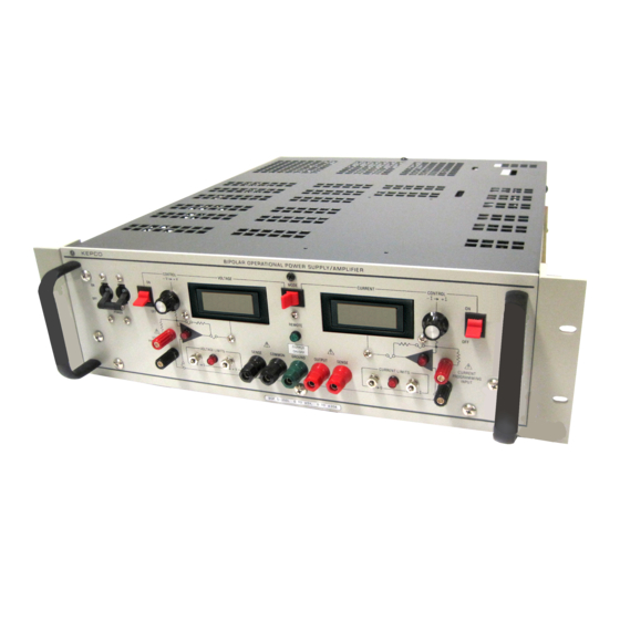
- Page 4 FIGURE 2. BOP FULL RACK, FRONT PANEL CONTROLS, INDICATORS AND TERMINATIONS FIGURE 3. BOP 3/4 RACK, FRONT PANEL CONTROLS, INDICATORS AND TERMINATIONS KEPCO, INC. 131-38 SANFORD AVENUE FLUSHING, NY. 11355 U.S.A. TEL (718) 461-7000 FAX (718) 767-1102 http://www.kepcopower.com email: hq@kepcopower.com...
- Page 5 LATION. Periodic cleaning of the interior of the power sup- (~131°F). FIGURE 4. BOP REAR PANEL TERMINATIONS, TYPICAL FOR 3/4 RACK AND FULL RACK MODELS KEPCO, INC. 131-38 SANFORD AVENUE FLUSHING, NY. 11355 U.S.A. TEL (718) 461-7000 FAX (718) 767-1102 http://www.kepcopower.com email: hq@kepcopower.com 081415...
- Page 6 + V VOLTAGE LIMIT cation at hand. Always monitor the front panel meters while adjusting output voltage/current KEPCO, INC. 131-38 SANFORD AVENUE FLUSHING, NY. 11355 U.S.A. TEL (718) 461-7000 FAX (718) 767-1102 http://www.kepcopower.com email: hq@kepcopower.com 228-1678 REV 1...
- Page 7 6. Adjust the + V and – V VOLTAGE LIMIT potentiome- ters to the required output (compliance) values. Pro- ceed as follows: KEPCO, INC. 131-38 SANFORD AVENUE FLUSHING, NY. 11355 U.S.A. TEL (718) 461-7000 FAX (718) 767-1102 http://www.kepcopower.com email: hq@kepcopower.com 081415...
- Page 8 KEPCO, INC. 131-38 SANFORD AVENUE FLUSHING, NY. 11355 U.S.A. TEL (718) 461-7000 FAX (718) 767-1102 http://www.kepcopower.com email: hq@kepcopower.com 228-1678 REV 1 081415...
Need help?
Do you have a question about the BOP 100W and is the answer not in the manual?
Questions and answers