Sign In
Upload
Manuals
Brands
KEPCO Manuals
Power Supply
BOP-MG 1KW
KEPCO BOP-MG 1KW Manuals
Manuals and User Guides for KEPCO BOP-MG 1KW. We have
2
KEPCO BOP-MG 1KW manuals available for free PDF download: Operator's Manual
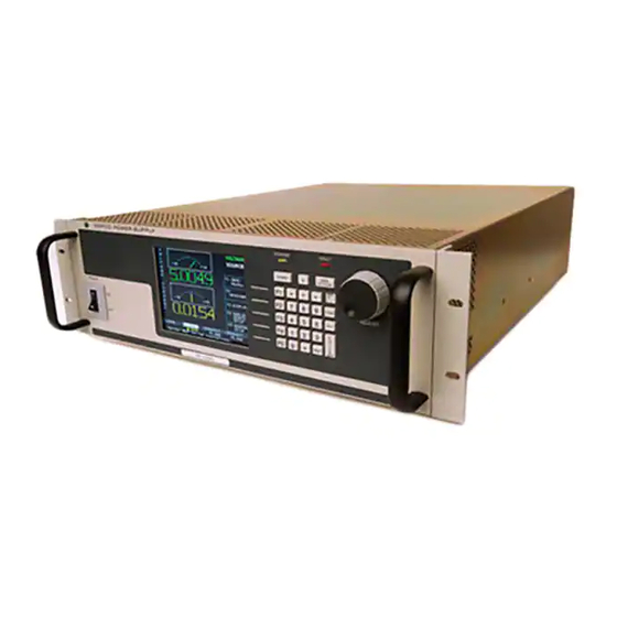
KEPCO BOP-MG 1KW Operator's Manual (234 pages)
HIGH POWER BIPOLAR POWER SUPPLY
Brand:
KEPCO
| Category:
Power Supply
| Size: 2.71 MB
Table of Contents
Table of Contents
9
List of Figures
17
Section 1 - Introduction
21
Scope of Manual
21
General Description
21
LXI Compatibility (ME Models)
22
Specifications
22
BOP General Specifications
23
Local Control
34
Remote Control
34
W BOP Power Supply, Outline Drawing
35
Features
37
Digital Calibration
37
Voltage/Current Protection
37
Waveforms
37
Saving and Recalling Settings
37
External Reference (Analog Control)
37
External Limits
38
User-Defined Voltage/Current Maximum Values (Software Limits)
38
Parallel and Series Configurations
38
Energy Recuperation
38
Equipment Supplied
38
Accessories
38
Accessories
39
Safety
40
BOP Output Characteristics
41
Section 2 - Installation
43
Unpacking and Inspection
43
Terminations and Controls
43
Rear Panel Connector Functions
44
IEEE 1118 Connector Input/Output Pin Assignments
45
External Protection Connector Input/Output Pin Assignments
46
Parallel/Serial Control in Port Pin Assignments
47
Analog I/O Port Input/Output Pin Assignments
48
Preliminary Operational Check
49
Installation
50
Rack Mounting
50
Slide Installation
50
Wiring Instructions
50
Safety Grounding
50
Source Power Connections
50
D-C Output Grounding
51
Earth-Ground Configuration
52
Grounding Network Configuration
52
Power Supply/Load Interface
52
Earth Ground Connection Recommendations
53
Load Connection - General
54
Load Connection Using Local Sensing
54
Load Connection Using Remote Sensing
54
Cooling
54
Setting up the Unit
55
Consider the Load Type
55
Setup for Local Operation
55
Setup for Fail Safe/Interlock PROTECTION
56
Setup for Remote Operation Via GPIB (MG Models Only)
57
Setup for Remote Operation Via RS 232C
57
Setup for Remote Operation Via LAN (ME Models Only)
58
Finding Kepco Power Supplies on the LAN
58
Bonjour-Enabled Discovery
58
LXI Discovery
59
Launch Web Interface
59
LAN Configuration Using Web Interface
60
Web Interface Configure LAN Page
61
Multiple Unit Configurations (MG Models Only)
62
Multiple Unit Connections
63
Parallel Configuration, Local Sensing, Typical
64
Parallel Configuration, Remote Sensing, Typical
65
Series Configuration, Local Sensing, Typical
66
Series Configuration, Remote Sensing, Typical
67
Multiple Unit Protection
68
Multiple Unit Source Power
68
Configuring Parallel, Series, 2 X 2 or 3 X 2 Combinations
69
Powering up Series/Parallel Combinations
70
Master Power up Screen
72
Power on Default Screen for Master Unit
73
Operating Instructions for Multiple Unit Combinations
74
Restoring a Unit to Standalone Operation
74
Changing Multiple Unit Configurations
74
X 2 (3 Series X 2 Parallel) Configuration, Local Sensing, Typical
75
Section 3 - Operation
77
General
77
Power Supply Basics
77
BOP Series Front Panel
78
Keypad Description
79
LCD and Power-Up Screen Description
80
Power-Up Screen Showing Graphic Meters
81
Turning the Power Supply on
82
How to Access the Menus
83
How to Modify a Parameter
84
Password Setup
85
How to Access a Password Protected Menu
86
Display Settings (Operator Convenience) Menu
87
Displaying Meters or Graph (Time Line)
88
Adjusting LCD Contrast and Background
88
Waveform Stop
88
Enabling/Disabling Audible Beeps
88
Display Settings (Operator Convenience) Menu
89
Local Mode Operation
90
Setting Local Mode
90
Keypad Lockout
90
Local Password Protection at Power-Up
90
Setting Voltage or Current Mode
90
Programming Voltage or Current and Associated Protect Limits
91
Voltage and Current Parameter Definitions
92
Selecting Bipolar/Independent Protection Limits
93
Understanding Voltage and Current Protect Limits
94
Hidden Voltage and Current Protect Limits
94
Changing Maximum or Minimum Software-Controlled Limits
94
Max/Min Settings Menu
95
Changing Maximum Accepted Voltage or Current (Main Channel Software Limits)
96
Changing Maximum/Minimum Protection Software-Controlled Limits
97
External Limits
98
Enabling/Disabling DC Output Power
98
Using the Trigger Port to Customize Output On/Off Operation
98
Determining How the Unit Responds When Output Is off (Load Type)
98
Power Supply Behavior When Output Is Set to off
99
Battery Charging/Discharging Using the BOP
101
Battery Operations Using Voltage Mode
101
Battery Operations Using Current Mode
101
Changing the Default Power up Settings
102
Power up Settings Menu
103
Storing/Recalling Power Supply Output Settings
104
Understanding Abbreviations Used for Saved Settings
105
Viewing Saved Settings
106
Saving Settings and Erasing or Modifying Previously Saved Settings
106
Saved Setups Menu
107
Copying Previously Saved Settings to a New Location
108
Applying Saved Settings to the Output (Recall)
108
Waveform Generation
108
Protecting the Load When Accessing Waveforms
108
Waveform Overview
108
Understanding How Waveforms Are Generated
109
Waveform Specifications
110
Viewing Stored Waveforms
111
Creating a New Waveform
111
New Waveform Menu
112
Waveform Segment Details Menu
113
Executing a Waveform
114
Modifying Previously Stored Waveforms
115
Using Segments to Build a Waveform
116
Copying a Waveform
118
Reset
118
Operator Testing
118
Revisions/Test Menu
119
Error Message Explanations
120
Analog Remote Mode Programming
121
Suppressing Noise at the Output
121
Remote Output off
121
Remote Shutdown
122
Remote Standby
123
Voltage/Current Mode Control
124
Controlling the Output Using the BOP as a Power Amplifier
124
Fixed Gain Using External Reference Control
125
Variable Gain Using External Reference Level
126
External Protection Limits
126
Using both Local/Digital and External Protection Limits
127
Monitoring Output Current Using an Analog Signal
128
Digital Remote Mode Programming
128
Operating Features Available Only by Remote Commands
128
Measurement Capabilities
128
Maximum Setpoint to Measurement Response
129
New or Modified Commands
129
Power-Up Defaults
129
How to Implement Maximum Setpoint to Measurement Specification
129
Programming Techniques to Optimize Performance
130
Programming Voltage/Current Limit and Current/Voltage Limit
130
Making Sure the Previous Command Is Complete
131
Remote Mode Setup
132
Determining Whether *RST Command Sets the Output off or on
133
GPIB Port Setup (MG Models ONLY)
133
Changing the GPIB Address
134
Establish Communication Language
134
Configure Device Clear (DCL) Control
134
RS 232 Serial Port Setup
134
Select Baud Rate
134
Configure XON/XOFF Protocol
134
Configure Prompt Mode
135
LAN Interface Setup (ME Models Only)
135
Set IP Address
136
Change IP Address Mask
136
Configure Auto IP
136
Configure DHCP
136
Configure Host Name
136
Configure Index
137
BIT 4882 Compatibility
137
BIT 4886 Compatibility
137
LIST Command Differences in BIT 4886
137
Status Reporting Differences in BIT 4886
137
Trigger Operation Differences in BIT 4886
137
IEEE 488 (GPIB) Bus Protocol (MG Models Only)
138
BOP VISA Instrument Driver
139
RS232-C Operation
140
Serial Interface
140
RS 232 Implementation
140
RS 232 Implementation
141
XON XOFF Method
142
Echo Mode
142
Prompt Method
143
Using SCPI Commands for RS 232 Communication
143
Isolating RS 232 Communication Problems
143
LAN Operation (ME Models Only)
143
LAN Factory Defaults
144
Remote Programming Using the Web Interface
144
Troubleshooting LAN Communication Problems
144
Launch Web Interface
145
LAN Configuration Using Web Interface
146
Operating the Unit Using Web Interface
147
Changing the Output
148
Resetting the Unit (*RST)
149
Using a Waveform (User-Programmed Sequences)
149
SCPI Programming
150
SCPI Messages
151
Common Commands/Queries
151
SCPI Subsystem Command/Query Structure
151
Abort Subsystem
151
Initiate Subsystem
151
LIST Subsystem
151
Tree Diagram of SCPI Commands Used with BOP Power Supply
152
Measure Subsystem
153
Output Subsystem
153
Memory Subsystem
154
Status Subsystem
154
Trigger Subsystem
154
Source:]Voltage and [Source:]Current Subsystems
154
Calibrate Subsystem
155
System Subsystem
155
Forgotten Passwords
155
Program Message Structure
155
Keyword
156
Keyword Separator
156
Query Indicator
156
Data
156
Data Separator
156
Message Unit Separator
156
Root Specifier
156
Message Terminator
158
Understanding the Command Structure
158
Program Message Syntax Summary
159
Status Reporting
159
Status Reporting Structure
160
Operational Status Register
160
Status Reporting Structure
161
Questionable Status Register
162
SCPI Program Examples
162
Typical Example of BOP Power Supply Program Using SCPI Commands
163
Section 4 - Calibration
165
General
165
Test Equipment Requirements
166
Suggested Sense Resistors
167
Calibration Using Remote SCPI Commands Via GPIB or RS 232 Interface
168
Calibration Procedure Using SCPI Commands
169
Calibration Setup for Current Mode
172
Calibration Using Front Panel Keypad in Local Mode
174
Understanding the Calibration Process
174
Main Calibration Screen
175
Calibration Procedure Using Local Mode
176
Calibration Storage
180
A.2 *CLS — Clear Status Command
181
A.4 *ESE? — Standard Event Status Enable Query
182
A.8 *OPC? — Operation Complete Query
183
A.9 *OPT? — Options Query
184
A.12 *SAV — Save Command
185
A.16 *TRG — Trigger Command
186
B.1 Introduction
187
B.2 Numerical Values
189
B.6 Initiate:continuous Command
190
B.8 Measure? Query
191
B.13 Measure:rate? Query
192
B.18 Memory:location? Query
193
Using Memory Location Commands and Queries
194
B.19 Memory:pack Command
194
Using List Commands to Measure Sample at End of Pulse
195
B.22 Output[ : State] Query
195
Using List Commands to Measure Sample at Start of Pulse
196
B.23 Output:control Command
196
B.24 Output:control? Query
197
B.31 [Source:]Current[:Level]:Limit:neg Command
198
B.36 [Source:]Current:mode? Query
199
B.38 [Source:]Current[:Level]:Protect[:Both] Query
200
B.45 [Source:]Current[:Level]:Protect:limit[:Both] Command
201
B.51 [Source:]Current[:Level]:Triggered[:Amplitude] Command
202
B.58 [Source:]List:copy Command
203
Using LIST Commands and Queries
204
B.60 [Source:]List:count? Query
204
Creating and Executing a Complex Waveform Using LIST Commands
205
B.62 [Source:]List:count:skip? Query
205
B-3 List Data Table
206
B.68 [Source:]List:current:points? Query
207
B.73 [Source:]List:dwell? Query
208
B.80 [Source:]List:resolution? Query
209
Multiple External Devices Using a Single External Pulse
210
B-8 Using List:wait Commands to Control Generation of a Waveform Measured by Multiple External Devices Using a Single External Pulse
210
Using List:wait Commands to Allow an External Device Time to Function While Imposing a Maximum Wait Time
211
B.83 [Source:]List:sample? Query
212
B.92 [Source:]List:set:wait? QUERY
213
B.94 [Source:]List : Voltage Command
214
B.99 [Source:]List : Voltage:points? Query
215
Using List:wait Commands to Control Generation of a Waveform Measured
216
By Multiple External Devices Using the Low-Going Leading Edge of an External Pulse
216
B.102 [Source:]List:wait:low Command
216
B.103 [Source:]Voltage[:Level][:Immediate][:Amplitude] Command
217
B.110 [Source:]Voltage[:Level]:Limit:positive? Query
218
Using PROT:LIM:POS and PROT:LIM:POS Commands to Set Asymmetrical Limits
219
B.114 [Source:]Voltage[:Level]:Protect[:Both]? Query
219
B.119 [Source:]Voltage[:Level]:Protect:positive Command
220
B.126 [Source:]Voltage[:Level]:Protect:limit:positive? Query
221
B.132 Status:operation[:Eventi ] Query
222
Using Status Commands and Queries
223
B.137 Status:questionable:enable? Query
223
B.138 System:beep Command
224
B.146 System:communication:lan:ip? Query
225
B.153 System:communication:serial:echo Command
226
B.160 System:error:code? Query
227
B.168 System:mdns:name? Query
228
B.176 System:remote? Query
229
Using System Commands and Queries
230
B-6 Error Messages
230
Advertisement
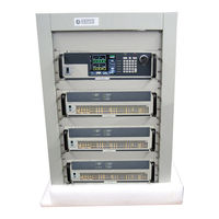
KEPCO BOP-MG 1KW Operator's Manual (198 pages)
HIGH POWER BIPOLAR POWER SUPPLY
Brand:
KEPCO
| Category:
Power Supply
| Size: 2.19 MB
Table of Contents
Table of Contents
11
Power Supply
1
Declaration of Conformity
3
Safety Instructions
5
Safety Messages
6
Warnings and Cautions
9
List of Figures
18
General Description
21
Scope of Manual
21
Specifications
21
BOP General Specifications
22
Local Control
32
Remote Control
32
W BOP Power Supply, Outline Drawing
33
Rear View
34
Digital Calibration
35
Features
35
Saving and Recalling Settings
35
Voltage/Current Protection
35
Waveforms
35
Energy Recuperation
36
Equipment Supplied
36
External Limits
36
External Reference (Analog Control)
36
Parallel and Series Configurations
36
User-Defined Voltage/Current Maximum Values (Software Limits)
36
Accessories
37
Safety
38
BOP Output Characteristics
39
Section 2 - Installation
41
Unpacking and Inspection
41
Terminations and Controls
41
BOP Series Rear Panel
41
Rear Panel Connector Functions
42
Trigger Port Pin Assignments
43
RS232C PORT Input/Output Pin Assignments
44
Parallel/Serial Protect in Port Pin Assignments
45
Preliminary Operational Check
46
IEEE 488 Port Input/Output Pin Assignments
47
Installation
48
Rack Mounting
48
Slide Installation
48
Wiring Instructions
48
Safety Grounding
48
Source Power Connections
48
D-C Output Grounding
48
Earth-Ground Configuration
49
Earth Ground Connection Recommendations
50
Grounding Network Configuration
51
Power Supply/Load Interface
51
Load Connection - General
51
Load Connection Using Local Sensing
52
Load Connection Using Remote Sensing
52
Cooling
52
Setting up the Unit
52
Consider the Load Type
52
Setup for Local Operation
53
Load Connections, Local Sensing
53
Setup for Remote Operation Via GPIB
54
Setup for Remote Operation Via RS 232C
54
Load Connections, Remote Sensing
54
Multiple Unit Configurations
55
Multiple Unit Connections
55
Parallel Configuration, Local Sensing, Typical
56
Parallel Configuration, Remote Sensing, Typical
57
Series Configuration, Local Sensing, Typical
58
Series Configuration, Remote Sensing, Typical
59
Multiple Unit Protection
60
Multiple Unit Source Power
60
Configuring Parallel, Series, 2 X 2 or 3 X 2 Combinations
61
Powering up Series/Parallel Combinations
62
Master Power up Screen
64
Operating Instructions for Multiple Unit Combinations
65
Power on Default Screen for Master Unit
65
Power on Default Screen for Slave Unit
65
Restoring a Unit to Standalone Operation
66
Changing Multiple Unit Configurations
66
X 2 (3 Series X 2 Parallel) Configuration, Local Sensing, Typical
67
Section 3 - Operation
69
General
69
Power Supply Basics
69
Keypad Description
69
BOP Series Front Panel
69
Front Panel Keypad
70
LCD and Power-Up Screen Description
71
Power-Up Screen Showing Graphic Meters
72
Turning the Power Supply on
73
How to Access the Menus
74
How to Modify a Parameter
75
Password Setup
75
How to Access a Password Protected Menu
76
Operator Convenience Functions (Display Menu)
77
Adjusting LCD Brightness, Contrast and Background
77
Password Protection Menu, Factory Defaults
77
Displaying Programmed Settings in Remote Mode
78
Enabling/Disabling Audible Beeps
79
Displaying Meters or Graph (Time Line)
79
Waveform Stop
79
Local Mode Operation
79
Setting Local Mode
79
Keypad Lockout
79
Local Password Protection at Power-Up
80
Setting Voltage or Current Mode
80
Programming Voltage or Current and Associated Protect Limits
80
Voltage and Current Parameter Definitions
81
Selecting Bipolar/Independent Protection Limits
82
General Setup Menu
83
Understanding Voltage and Current Protect Limits
84
Hidden Voltage and Current Protect Limits
84
Changing Maximum or Minimum Software-Controlled Limits
84
Changing Maximum Accepted Voltage or Current (Main Channel Software Limits)
85
Changing Maximum/Minimum Protection Software-Controlled Limits
86
External Limits
87
Enabling/Disabling DC Output Power
87
Determining How the Unit Responds When Output Is off (Load Type)
87
Power Supply Behavior When Output Is Set to off
88
Battery Charging/Discharging Using the BOP
89
3.3.6.1.1 Battery Operations Using Voltage Mode
89
3.3.6.1.2 Battery Operations Using Current Mode
90
Changing the Default Power up Settings
91
Storing/Recalling Power Supply Output Settings
92
Understanding Abbreviations Used for Saved Settings
92
Save/Recall Menu
93
Viewing Saved Settings
94
Saving Settings and Erasing or Modifying Previously Saved Settings
94
Copying Previously Saved Settings to a New Location
95
Applying Saved Settings to the Output (Recall)
95
Waveform Generation
95
Protecting the Load When Accessing Waveforms
95
Waveform Overview
95
Understanding How Waveforms Are Generated
96
Sine, Triangle and Ramp Waveform Frequency Vs. Points
97
Waveform Specifications
98
Viewing Stored Waveforms
98
Executing a Waveform
98
Waveform Settings Menu
98
Modifying Previously Stored Waveforms
99
Creating a New Waveform
99
Waveform Segment Details Menu
100
Using Segments to Build a Waveform
101
Sample Waveform
102
Copying a Waveform
103
Reset
104
Operator Testing
104
Error Message Explanations
104
Error Message Explanations
105
Analog Remote Mode Programming
106
Remote Output off
106
Remote Shutdown
106
Remote Shutdown Using External Power, Standalone or Multiple Units
106
Remote Standby
107
Remote Shutdown Using Internal Power, Multiple Units
107
Remote Shutdown Using Internal Power, Standalone Units
107
Remote Standby, Standalone or Multiple Units
107
Voltage/Current Mode Control
108
Controlling the Output Using the BOP as a Power Amplifier
108
Fixed Gain Using External Reference Control
108
Variable Gain Using External Reference Level
109
External Protection Limits
110
Using both Local/Digital and External Protection Limits
111
Monitoring Output Current Using an Analog Signal
111
Digital Remote Mode Programming
111
Operating Features Available Only by Remote Commands
112
Expanded Waveforms and Programs
112
Programming Techniques to Optimize Performance
112
Programming Voltage/Current Limit and Current/Voltage Limit
112
Making Sure the Previous Command Is Complete
113
Remote Mode Setup
114
Programming Example to Verify Previous Command Has Completed
114
GPIB Port Setup
115
3.5.3.1.1 Changing the Gpib Address
115
3.5.3.1.2 Configure Device Clear (Dcl) Control
116
3.5.3.1.3 Determining Whether *Rst Command Sets the Output off or on
116
RS 232 Serial Port Setup
116
3.5.3.2.1 Select Baud Rate
116
3.5.3.2.2 Configure Xon/Xoff Protocol
116
3.5.3.2.3 Configure Prompt Mode
116
Establish Communication Language
117
BIT 4882 Compatibility
117
BIT 4886 Compatibility
117
3.5.3.5.1 List Command Differences in Bit 4886
117
3.5.3.5.2 Status Reporting Differences in Bit 4886
117
3.5.3.5.3 Trigger Operation Differences in Bit 4886
118
IEEE 488 (GPIB) Bus Protocol
118
BOP VISA Instrument Driver
119
RS232-C Operation
120
Serial Interface
120
RS 232 Implementation
120
3.5.6.2.1 Xon Xoff Method
122
3.5.6.2.2 Echo Mode
122
3.5.6.2.3 Prompt Method
122
Using SCPI Commands for RS 232 Communication
122
Isolating RS 232 Communication Problems
122
SCPI Programming
123
SCPI Messages
123
Common Commands/Queries
124
SCPI Subsystem Command/Query Structure
124
Abort Subsystem
124
Display Subsystem
124
Initiate Subsystem
124
LIST Subsystem
124
Tree Diagram of SCPI Commands Used with BOP Power Supply
125
Measure Subsystem
127
Output Subsystem
127
Memory Subsystem
127
Status Subsystem
127
Trigger Subsystem
127
Source:]Voltage and [Source:]Current Subsystems
128
Calibrate Subsystem
128
System Subsystem
128
3.6.3.12.1 Forgotten Passwords
128
Program Message Structure
129
Message Structure
129
Keyword
130
Keyword Separator
130
Query Indicator
130
Data
130
Data Separator
131
Message Unit Separator
131
Root Specifier
131
Message Terminator
131
Understanding the Command Structure
131
Program Message Syntax Summary
132
Status Reporting
133
Status Reporting Structure
133
Operational Status Register
133
Questionable Status Register
135
SCPI Program Examples
135
Typical Example of BOP Power Supply Program Using SCPI Commands
136
Section 4 - Calibration
137
General
137
Test Equipment Requirements
138
Suggested Sense Resistors
139
Calibration Using Remote SCPI Commands Via GPIB or RS 232 Interface
140
Calibration Procedure Using SCPI Commands
141
Calibration Setup for Current Mode
144
Calibration Using Front Panel Keypad in Local Mode
146
Understanding the Calibration Process
146
Main Calibration Screen
147
Calibration Procedure Using Local Mode
148
Calibration Storage
151
Calibration Storage
152
Appendix A - Scpi Common Command/Query Definitions
153
CLS - Clear Status Command
153
ESE - Standard Event Status Enable Command
153
A.2 *CLS — Clear Status Command
153
ESE? - Standard Event Status Enable Query
154
ESR? - Event Status Register Query
154
IDN? - Identification Query
154
OPC - Operation Complete Command
154
A.4 *ESE? — Standard Event Status Enable Query
154
OPC? - Operation Complete Query
155
A.8 *OPC? — Operation Complete Query
155
OPT? - Options Query
156
A.10 *Rcl - Recall Command
156
A.11 *Rst - Reset Command
156
A.9 *OPT? — Options Query
156
A.12 *Sav - Save Command
157
A.13 *Sre - Service Request Enable Command
157
A.14 *Sre? - Service Request Enable Query
157
A.15 *Stb? - Status Byte Register Query
157
A.16 *Trg - Trigger Command
158
A.17 *Tst? - Self Test Query
158
A.18 *Wai - Wait-To-Continue Command
158
Appendix B - Scpi Command/Query Definitions
159
Introduction
159
B.1 Introduction
159
Numerical Values
160
Abort COMMAND
160
B.2 Numerical Values
160
B-1 Programming the Output
161
Ent [:DC]? Query
162
Using List Commands to Measure Sample at End of Pulse
163
Using List Commands to Measure Sample at Start of Pulse
164
Ut [:STAT E ] Command
164
Ut :CONT Rol Command
165
Query
166
B-4 Setting Limits
167
Ce :]CURR Ent :Mode? Query
168
El ]:PROT Ect :MODE Command
169
El ]:PROT Ect :LIM It [:BOTH]? Query
170
Ce :]FUNC Tion :MODE? Query
171
B-5 Using LIST Commands and Queries
172
B-2 List Data Table
174
APPL y :SWE Ep ? Query
175
B-6 Using List:wait Commands to Control Generation of a Waveform Measured by Multiple External Devices Using a Single External Pulse
177
Multiple External Devices Using a Single External Pulse
177
Using List:wait Commands to Allow an External Device Time to Function While Imposing a Maximum Wait Time
178
VOLT Age Command
179
Ce :]LIST:SET:WAIT? QUERY
180
Command
181
Ce :]List:wait:ledge Command
182
B-8 Using List:wait Commands to Control Generation of a Waveform Measured by Multiple External Devices Using the Low-Going Leading Edge of an External Pulse
183
Multiple External Devices Using the Low-Going Leading Edge of an External Pulse
183
Command
184
Ce :]VOLT Age :MODE? Query
185
Using PROT:LIM:POS and PROT:LIM:POS Commands to Set Asymmetrical Limits
186
Itive ? Query
187
It :POS Itive ? Query
188
B-4 Questionable Event Register, Questionable Condition Register and Questionable Condition Enable Register Bits
189
Using Status Commands and Queries
190
B.122 SYST Em :BEEP Command
191
B.130 System:communication:serial:pace? Query
192
CEN Able Command
193
Using System Commands and Queries
194
B-5 Error Messages
195
Bop-1K
196
Advertisement
Related Products
KEPCO BOP-MG
KEPCO BOP-MG/ME 1KW
KEPCO BOP-ME 1KW
KEPCO BOP 6-125MG
KEPCO BOP 50-20MG
KEPCO BOP 36-12
KEPCO BOP 100-4
KEPCO BOP 40-50ME
KEPCO BOP 144-14ME
KEPCO BOP 10-75ME
KEPCO Categories
Power Supply
Adapter
Protection Device
Racks & Stands
Cables and connectors
More KEPCO Manuals
Login
Sign In
OR
Sign in with Facebook
Sign in with Google
Upload manual
Upload from disk
Upload from URL