Table of Contents
Advertisement
Quick Links
OPERATOR'S MANUAL
KEPCO INC.
An ISO 9001 Company.
IMPORTANT NOTES:
1)
This manual is valid for the following Model and associated serial numbers:
MODEL
2)
A Change Page may be included at the end of the manual. All applicable changes and
revision number changes are documented with reference to the equipment serial num-
bers. Before using this Instruction Manual, check your equipment serial number to identify
your model. If in doubt, contact your nearest Kepco Representative, or the Kepco Docu-
mentation Office in New York, (718) 461-7000, requesting the correct revision for your
particular model and serial number.
3)
The contents of this manual are protected by copyright. Reproduction of any part can be
made only with the specific written permission of Kepco, Inc.
Data subject to change without notice.
©2011, KEPCO, INC
P/N 228-1733
KEPCO, INC. ! 131-38 SANFORD AVENUE ! FLUSHING, NY. 11355 U.S.A. ! TEL (718) 461-7000 ! FAX (718) 767-1102
HIGH VOLTAGE BIPOLAR
POWER SUPPLY
MODEL
BOP 500M, BOP1000M
POWER SUPPLY
SERIAL NO.
email: hq@kepcopower.com ! World Wide Web: http://www.kepcopower.com
REV. NO.
KEPCO
THE POWER SUPPLIER™
®
Advertisement
Table of Contents

Subscribe to Our Youtube Channel
Related Manuals for KEPCO BOP 500M


Summary of Contents for KEPCO BOP 500M
-
Page 1: Power Supply
Data subject to change without notice. KEPCO ® ©2011, KEPCO, INC THE POWER SUPPLIER™ P/N 228-1733 KEPCO, INC. ! 131-38 SANFORD AVENUE ! FLUSHING, NY. 11355 U.S.A. ! TEL (718) 461-7000 ! FAX (718) 767-1102 email: hq@kepcopower.com ! World Wide Web: http://www.kepcopower.com... - Page 3 Service must be referred to authorized personnel. Using the power supply in a manner not specified by Kepco. Inc. may impair the protection provided by the power supply. Observe all safety precautions noted throughout this manual. The following table lists symbols used on the power supply or in this manual where applicable.
-
Page 5: Declaration Of Conformity
93/68/EEC (CE mark) Standard to which Conformity is declared: EN61010-1:2001 (Safety requirements for electrical equipment for measurement, control and laboratory use - Part 1) KEPCO INC. Manufacturer's Name and Address: 131-38 SANFORD AVENUE FLUSHING, N.Y. 11355 USA Importer's Name and Address:... - Page 6 There are no user or operator serviceable parts within the product enclosure. Refer all servicing to qualified and trained Kepco service technicians. 228-1351 COND/CONFORM 020411...
- Page 7 SAFETY INSTRUCTIONS 1. Installation, Operation and Service Precautions This product is designed for use in accordance with EN 61010-1 and UL 3101 for Installation Category 2, Pollution Degree 2. Hazardous voltages are present within this product during normal operation. The prod- uct should never be operated with the cover removed unless equivalent protection of the operator from accidental contact with hazardous internal voltages is provided: There are no operator serviceable parts or adjustments within the product enclosure.
-
Page 9: Table Of Contents
TABLE OF CONTENTS SECTION PAGE SECTION 1 - INTRODUCTION Scope of Manual ............................. 1-1 General Description..........................1-1 Electrical Specifications, General......................1-1 Electrical Specifications, Performance ....................1-2 Miscellaneous Features .......................... 1-4 Mechanical Specifications ........................1-6 Accessories ............................. 1-7 SECTION 2 - INSTALLATION Unpacking And Inspection........................ - Page 10 LIST OF FIGURES FIGURE TITLE PAGE BOP (High Voltage) Operational Power Supply .................... iv BOP Output Characteristic ......................... 1-4 BOP Output Waveform with Phase Shift....................1-5 Mechanical Outline Drawing, BOP – HV ....................1-8 Location of Internal Calibration Controls ....................2-1 BOP Terminations and Controls.........................
-
Page 11: List Of Tables
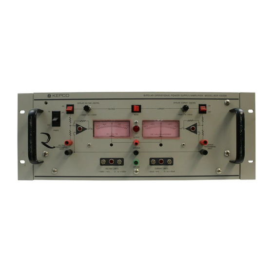
LIST OF TABLES TABLE TITLE PAGE Output Ranges and Impedance ........................1-2 Output Effects, Offsets and Reference Specifications ................1-2 Dynamic Specifications ..........................1-4 Internal Calibration Controls ........................2-1 BOP Terminations and Controls .........................2-3 BOP1000SVC020411... - Page 12 FIGURE 1-1. BOP (HIGH VOLTAGE) OPERATIONAL POWER SUPPLY BOPSVC020411 /1107/1108...
-
Page 13: Section 1 - Introduction
Flushing, New York, U.S.A. GENERAL DESCRIPTION The Kepco Model BOP 500M and BOP 1000M are high voltage power sources, which combine the capabilities of fast programmable power supplies with a Class A output stage, which can respond bidirectionally from zero. The “BOP” can be operated in a “Voltage Stabilizing” or “Cur- rent Stabilizing”... -
Page 14: Electrical Specifications, Performance
<200 mV (1) Specifications are expressed as a percentage of the nominal power supply output (either voltage or current for either BOP 500M or BOP 1000M). (2) Common terminal grounded so that the common-mode current does not flow through the load. - Page 15 NOTE: In this instruction manual, Kepco will follow the NEMA standards for d-c Power Supplies and speak of the “Output Effects,” caused by changes in the “Influence Quantities.” The “Output Effects” are specified either as a percentage change, referred to the maximum , ∆I...
-
Page 16: Miscellaneous Features
(Output response to a step program) and in the frequency domain (bandwidth) for large and small signals. TABLE 1-3. DYNAMIC SPECIFICATIONS VOLTAGE CHANNEL CURRENT CHANNEL DYNAMIC SPECIFICATIONS BOP 500M BOP 1000M BOP 500M BOP 1000M Closed Loop Gain 50 V/V... -
Page 17: Bop Output Waveform With Phase Shift
NOTE: The BOP is operating as a SOURCE if the direction of its output voltage is the same as the direction of its output current. The BOP is operating as a SINK if the direction of its output voltage is opposite that of its output current. An illustrative case is shown in FIG. 1-3, where the BOP is programmed to deliver a sine wave output and where the load produces a phase shift between the output voltage and current. -
Page 18: Mechanical Specifications
VOLTAGE CONTROL CHANNEL (refer to Section 3 - FIG. 3-1). The BIPOLAR VOLTAGE AMPLIFIER, with a fixed gain of 50 (BOP 500M) or 100 (BOP 1000M) is connected, via the MODE switch, to the (unity gain) VOLTAGE PREAMPLIFIER. If the BIPOLAR VOLTAGE SWITCH is “on”, the BOP output voltage can be locally controlled by means of the (front... -
Page 19: Accessories
ACCESSORIES MOUNTING FLANGES, for installation of the BOP into a standard (19-inch) equipment rack (refer to Section 2, FIG. 2-5). (A pair included with each BOP). Kepco Part No. 128- 1282 (right), 128-1281 (left). REAR PROGRAMMING CONNECTOR, Kepco Model PC-9, 30-terminal printed circuit connector for all rear programming connections and flag signal outputs (One included with each BOP). -
Page 20: Mechanical Outline Drawing, Bop – Hv
FIGURE 1-4. MECHANICAL OUTLINE DRAWING, BOP – HV BOPHV020411... -
Page 21: Section 2 - Installation
SECTION 2 - INSTALLATION UNPACKING AND INSPECTION This instrument has been thoroughly inspected and tested prior to packing and is ready for operation. After carefully unpacking, inspect for shipping damage before attempting to operate. Perform the preliminary operation check as outlined in PAR. 2.5. If any indication of damage is found, file an immediate claim with the responsible transport service. -
Page 22: Bop Terminations And Controls
FIGURE 2-2. BOP TERMINATIONS AND CONTROLS BOPHV 020411... -
Page 23: Bop Terminations And Controls
Mechanical voltmeter zero adjustment Mechanical ammeter zero adjustment VOLTAGE LIMIT LED lamp, indicating voltage limiting operation Controls for manual adjustment of the (±) voltage limits BOP 500M BOP 1000M ± VOLTAGE LIMIT A = 500V TO 0 -1000V TO 0... -
Page 24: A-C Power Input Requirements
A-C POWER INPUT REQUIREMENTS The BOP is equipped with a SOURCE VOLTAGE SELECTOR permitting the user to choose between 115 and 230V a-c operation by means of a screwdriver actuated switch; the switch is accessed by removing the cover (see Section 5, PAR. 5.2). The switch location is illustrated in FIG. -
Page 25: Rear Programming Connector Wired For Front Panel Operation
FIGURE 2-4. REAR PROGRAMMING CONNECTOR WIRED FOR FRONT PANEL OPERATION Note: The rear sensing links must be attached to the rear terminals of the BOP as shown in FIG. 2-2 and the rear connector must be attached and secured. Set the BOP front panel controls as follows (refer to FIG. 2-2). The controls will be identified here and in the following manual text with the nomenclature used in Table 2-2 and identify- ing numbers used in FIG. -
Page 26: Installation
Turn on BIPOLAR CURRENT CONTROL (16) clockwise through its range, while observing the front panel “I METER” (17). The BOP output current should smoothly follow from the maximum negative output current, over zero, to the maximum positive output current of the BOP. -
Page 27: Section 3 - Operation
SECTION 3 - OPERATION INTRODUCTION BOP BIPOLAR OPERATIONAL POWER SUPPLIES can be used in a great variety of applica- tions. As a PRECISION VOLTAGE or CURRENT SOURCE, the BOP output can be controlled locally (by means of the front panel BIPOLAR voltage and current controls) or remotely (by means of resistances or by voltage signals). -
Page 28: Bop Voltage Control Channel
DIAGRAMS. Application and test set-up diagrams on the following pages show the sym- bolic and simplified representation of the BOP circuitry in four (4) separate diagrams, as indicated on FIGS. 3-1 through 3-4. The diagrams represent the four programmable cir- cuits of the BOP. -
Page 29: Bop Current Control Channel
FIGURE 3-2. BOP CURRENT CONTROL CHANNEL FIGURE 3-3. BOP (±) VOLTAGE LIMITING CIRCUIT BOPHV020411... -
Page 30: Bop (±) Current Limiting Circuit
FIGURE 3-4. BOP (±) CURRENT LIMITING CIRCUIT LOAD CONNECTION (I): The basic interconnection between the BOP and the load are shown in FIG. 3-5. The load wire size for the 2-wire connection shown should be as large as practicable to keep the series resistance and inductance low. In addition, the load wire pair should be tightly twisted, to reduce possible “pick-up”... - Page 31 LOAD CONNECTION (II). The recommended load connection for all applications requiring minimum load effect across a remote load is shown in FIG. 3-6. A twisted, shielded pair of wires (AWG No. 20 minimum) is connected from the BOP sensing terminals to the load. This “remote error sensing”...
- Page 32 only, to which all input source grounds, shields and load grounds are connected. Multiple signal grounds in the BOP output/load circuit may cause “ground loop” problems, since noise signals develop across the impedance between the multiple ground points. The exact physical location of the “best” single ground must be carefully selected for minimum ripple/noise output.
-
Page 33: Bop Operation With Local (Front Panel) Output Control
BOP OPERATION WITH LOCAL (FRONT PANEL) OUTPUT CONTROL 3.2.1 VOLTAGE MODE OPERATION WITH CURRENT LIMITING The BOP may be used as a stabilized (d-c) source of positive or negative voltage with output current limiting for either polarity pre-selected for the application at hand. Determine the output current and voltage requirement of your load. -
Page 34: Bop Operation With Remote Control Of The Voltage Control Channel
E BIPOLAR AMPS have respective gains of 50 (BOP 500M) and 100 (BOP 1000M), a d-c input signal of zero to (±)10V will control the BOP output through its specified range. In the local (front panel) control mode, the d-c control potential is applied via the BIPOLAR VOLTAGE CONTROL. -
Page 35: Remote Potentiometer Control Of The Bop D-C Output Voltage
Since Eref is either (+) or (–) 10 volts (depending on the position of S1) and the gain ratio Rf/Ri is variable from zero to one, the output voltage (E PRE-AMP) will be inverted and vary linearly (from (–) 10 volts, through zero, to (+)10 volts) with the change in the decade resistance (Rf). -
Page 36: Remote D-C Voltage Control By Means Of D-C Signal Voltage
3-9. This programming system provides a resolution of 12-bits with a linearity of (±) 0.01%. The digital and the power supply grounds are isolated (optical isolation) to 1000 volts. Calibra- tion of the system is performed with the controls provided by the Kepco Digital Programmer. FIGURE 3-9. -
Page 37: The Bop As An Amplifier
(PROGRAM) INPUT, the BOP functions as a bipolar amplifier. As an amplifier, the BOP has a voltage gain of 50 (BOP 500M) and 100 (BOP 1000M) respectively, so that (as before with the d-c control signal) a bipolar a-c input signal with an amplitude of 20V (peak to peak) will drive the BOP output through its specified (±) output voltage range. -
Page 38: Graphs Of Possible Bop Input/Output Waveshapes
the exact opposite direction of the input signal) by addressing the non-inverting input of the E PRE-AMP instead of the front panel E PROGRAM INPUT (Inverting input of the E PREAMP). FIGURE 3-11. GRAPHS OF POSSIBLE BOP INPUT/OUTPUT WAVESHAPES NOTE: The phase shift between the input and output signals of the BOP unit working as an amplifier is 0 °... -
Page 39: Basic Programming Circuit For Use Of The Bop As A Bipolar Amplifier (Voltage Mode)
tude, the basic programming circuit in FIG. 3-12 must be modified if the external signal source cannot produce 10 volts and if the full BOP output voltage swing is required. FIGURE 3-12. BASIC PROGRAMMING CIRCUIT FOR USE OF THE BOP AS A BIPOLAR AMPLIFIER (VOLTAGE MODE) If the EXT. -
Page 40: Bop Operation With Remote Control Of The Current Control Channel
BIPOLAR AMP which drives the BIPOLAR OUTPUT STAGE with a fixed gain of 8mA per volt (BOP 500M) and 4 mA per volt (BOP 1000M) respectively. A d-c control signal from zero to(±)10 volts will, therefore, control the BOP output current through its specified range (refer to FIG. -
Page 41: Remote Control Of The Bop Current Channel
FIGURE 3-14. PROGRAMMING CIRCUIT FOR DRIVING THE BOP OUTPUT VOLTAGE WITH A HIGH IMPEDANCE SOURCE, USING THE NON-INVERTING INPUT OF THE PRE-AMPLIFIER FIGURE 3-15. LOCAL (FRONT PANEL) CONTROL OF THE BOP OUTPUT CURRENT WITH THE BIPOLAR CURRENT CONTROL 3.4.1 REMOTE CONTROL OF THE BOP CURRENT CHANNEL Since the requirements for the control of the BOP output current are the same as for program- ming the output voltage, and since the control circuitry is almost identical, all programming cir- cuit descriptions for programming the output voltage of the BOP can be applied for current... -
Page 42: Remote Potentiometer Control Of The Bop Output Current
programming. The current programming circuits are illustrated in FIGs. 3-16 to 3-22. Any excep- tions with respect to current channel programming are noted on the diagrams. NOTE: Adjust the “zero” output current point by means of the built-in “I ZERO” control. Make sure that the input of the BOP current channel is short-circuited to the ground signal. -
Page 43: Digital Control Of The Bop Output Current
FIGURE 3-18. DIGITAL CONTROL OF THE BOP OUTPUT CURRENT FIGURE 3-19. BOP OUTPUT CURRENT CONTROL WITH A HIGH IMPEDANCE (±) 1 VOLT SIGNAL SOURCE 3-17 BOPHV020411... -
Page 44: Basic Programming Circuit For Use Of The Bop As A Bipolar Current Stabilized Amplifier
FIGURE 3-20. BASIC PROGRAMMING CIRCUIT FOR USE OF THE BOP AS A BIPOLAR CURRENT STABILIZED AMPLIFIER FIGURE 3-21. PROGRAMMING CIRCUIT FOR DRIVING THE BOP OUTPUT CURRENT WITH A BIPOLAR SIGNAL LESS THAN ±10V (EXAMPLE SHOWN: ±1V SOURCE) 3-18 BOPHV020411... -
Page 45: Remote Control Of The Bop Current Limit
FIGURE 3-22. PROGRAMMING CIRCUIT FOR DRIVING THE BOP OUTPUT CURRENT WITH A HIGH IMPEDANCE SOURCE 3.4.2 REMOTE CONTROL OF THE BOP CURRENT LIMIT The BOP I LIMIT CIRCUIT in the local (front panel) control mode is shown in FIG. 3-23. A (+) 10 volt reference voltage is repeated and inverted to obtain two reference voltages (+10V and - 10V respectively). -
Page 46: Local (Front Panel) Control Of The Bop Current Limit Circuits
FIGURE 3-23. LOCAL (FRONT PANEL) CONTROL OF THE BOP CURRENT LIMIT CIRCUITS The BOP current limits can be remotely controlled by disconnecting the fixed reference poten- tial, setting the front panel controls to their maximum clockwise position, and substituting a vari- able (0 to 10 volt) reference potential. -
Page 47: Remote Control Of The Bop Voltage Limit
FIGURE 3-25. INDEPENDENT REMOTE CONTROL OF THE BOP (+) I AND (–) I LIMITS 3.4.3 REMOTE CONTROL OF THE BOP VOLTAGE LIMIT The BOP E LIMIT CIRCUIT in the local (front panel) control mode is shown in FIG. 3-26. The circuit functions in the same manner as the I LIMIT CIRCUIT described previously (refer to PAR. -
Page 48: Symmetrical Remote Control Of The Bop Voltage Limit Circuit
FIGURE 3-27. SYMMETRICAL REMOTE CONTROL OF THE BOP VOLTAGE LIMIT CIRCUIT FIGURE 3-28. INDEPENDENT REMOTE CONTROL OF THE BOP VOLTAGE LIMIT CIRCUITS 3-22 BOPHV020411...
Need help?
Do you have a question about the BOP 500M and is the answer not in the manual?
Questions and answers