Advertisement
Quick Links
OPERATOR'S MANUAL
200W: BOP 20-10, BOP 36-6, BOP 50-4, BOP 72-3, BOP 100-2, BOP 200-1
400W: BOP 20-20, BOP 36-12, BOP 50-8, BOP 72-6, BOP 100-4
KEPCO INC.
An ISO 9001 Company.
IMPORTANT NOTES:
1)
This manual is valid for the following Model and associated serial numbers:
MODEL
2)
A Change Page may be included at the end of the manual. All applicable changes and
revision number changes are documented with reference to the equipment serial num-
bers. Before using this Instruction Manual, check your equipment serial number to identify
your model. If in doubt, contact your nearest Kepco Representative, or the Kepco Docu-
mentation Office in New York, (718) 461-7000, requesting the correct revision for your par-
ticular model and serial number.
3)
The contents of this manual are protected by copyright. Reproduction of any part can be
made only with the specific written permission of Kepco, Inc.
Data subject to change without notice.
©2013, KEPCO, INC.
P/N 243-1308-r5a
KEPCO, INC.
BOP (M) (D) 100W, 200W, 400W
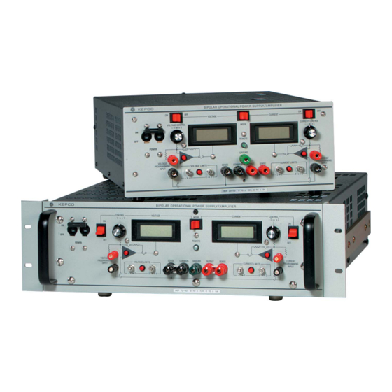
BIPOLAR POWER SUPPLY
100W: BOP 20-5, BOP 50-2, BOP 100-1
BOP 100W, 200W, 400W
POWER SUPPLY
SERIAL NO.
131-38 SANFORD AVENUE
FLUSHING, NY. 11355 U.S.A.
email: hq@kepcopower.com
MODEL
REV. NO.
KEPCO
THE POWER SUPPLIER™
TEL (718) 461-7000
World Wide Web: http://www.kepcopower.com
®
FAX (718) 767-1102
Advertisement

Subscribe to Our Youtube Channel
Summary of Contents for KEPCO BOP 100W
-
Page 1: Power Supply
Before using this Instruction Manual, check your equipment serial number to identify your model. If in doubt, contact your nearest Kepco Representative, or the Kepco Docu- mentation Office in New York, (718) 461-7000, requesting the correct revision for your par- ticular model and serial number. - Page 3 This upgrade must be accomplished at the Kepco factory in Flushing New York and includes component changes and re-calibration of the unit. Please contact Kepco Sales for price and delivery schedule regarding this upgrade.
- Page 4 AFTER PAR. 3-3 B) LOAD CONNECTION (I) and PAR. 3-3 C) LOAD CONNECTION (II) add the following: Load connections to the BOP power supply are achieved via the OUTPUT and COMMON ter- minals located on either the front or the rear panel, but not both. Sense connections must be made from the same location (front or rear panel) as the output and common connections.
- Page 5 The SN and SNR Programmers and the BIT 488 cards described in this manual are older meth- ods of controlling BOP power supplies via digital means. Although these products still function as described, the recommended method of digital control is now the use of Kepco’s BIT 4886 16-bit plug-in card with resolution of 1/2 .
- Page 6 NOTES (MASTER): PART OF 1. For Voltage Mode (shown) set MODE Switch to VOLTAGE and PC 12 VOLTAGE CONTROL Switch to ON. 2. For Current mode, set MODE Switch to CURRENT and CURRENT CONTROL Switch to ON. 3. If external control is needed, set the CONTROL switch to OFF and PART OF use either the corresponding VOLTAGE or CURRENT PC 12...
-
Page 7: Declaration Of Conformity
93/68/EEC (CE mark) Standard to which Conformity is declared: EN61010-1:2001 (Safety requirements for electrical equipment for measurement, control and laboratory use - Part 1) KEPCO INC. Manufacturer's Name and Address: 131-38 SANFORD AVENUE FLUSHING, N.Y. 11355 USA Importer's Name and Address:... - Page 8 There are no user or operator serviceable parts within the product enclosure. Refer all servicing to qualified and trained Kepco service technicians. 228-1351 COND/CONFORM 100913...
-
Page 9: Safety Instructions
SAFETY INSTRUCTIONS 1. Installation, Operation and Service Precautions This product is designed for use in accordance with EN 61010-1 and UL 3101 for Installation Category 2, Pollution Degree 2. Hazardous voltages are present within this product during normal operation. The product should never be operated with the cover removed unless equivalent protection of the operator from accidental contact with hazardous internal voltages is provided: There are no operator serviceable parts or adjustments within the product enclosure.


Need help?
Do you have a question about the BOP 100W and is the answer not in the manual?
Questions and answers