Table of Contents
Advertisement
Quick Links
OPERATOR'S MANUAL
HIGH PERFORMANCE, 400W
BIPOLAR OPERATIONAL POWER SUPPLY
KEPCO INC.
IMPORTANT NOTES:
1)
This manual is valid for the following Model and associated serial numbers:
MODEL
2)
A Change Page may be included at the end of the manual. All applicable changes and
revision number changes are documented with reference to the equipment serial num-
bers. Before using this Instruction Manual, check your equipment serial number to identify
your model. If in doubt, contact your nearest Kepco Representative, or the Kepco Docu-
mentation Office in New York, (718) 461-7000, requesting the correct revision for your par-
ticular model and serial number.
3)
The contents of this manual are protected by copyright. Reproduction of any part can be
made only with the specific written permission of Kepco, Inc.
Data subject to change without notice.
©2021, KEPCO, INC
P/N 243-1398
KEPCO, INC. 131-38 SANFORD AVENUE FLUSHING, NY. 11355 U.S.A. TEL (718) 461-7000 FAX (718) 767-1102
BOP -H SERIES
MODEL
BOP -H SERIES
POWER SUPPLY
ORDER NO.
SERIAL NO.
email: hq@kepcopower.com World Wide Web: ww.kepcopower.com
REV. NO.
REV. NO.
KEPCO
THE POWER SUPPLIER™
®
Advertisement
Table of Contents

Related Manuals for KEPCO BOP-H Series


Summary of Contents for KEPCO BOP-H Series
- Page 1 Data subject to change without notice. KEPCO ® ©2021, KEPCO, INC P/N 243-1398 THE POWER SUPPLIER™ KEPCO, INC. 131-38 SANFORD AVENUE FLUSHING, NY. 11355 U.S.A. TEL (718) 461-7000 FAX (718) 767-1102 email: hq@kepcopower.com World Wide Web: ww.kepcopower.com...
- Page 3 KEPCO ® KEPCO MODEL BOP 20-20HD THE POWER SUPPLIER™ NOTE: This manual applies to Kepco Model BOP 20-20HD, the first of a new BOP-H Series. It is equipped with the following options: • Option D (Display/Front Panel Control) • Option S (Master/Slave)
-
Page 5: Table Of Contents
TABLE OF CONTENTS SECTION PAGE SECTION 1 - INTRODUCTION Scope of Manual............................1-1 Options ............................... 1-1 1.2.1 Primary Options............................1-1 1.2.1.1 Display/Front Panel Control (D Option):..................... 1-1 1.2.1.2 Digital Remote Control (G Option, e Option)..................1-1 1.2.2 Secondary Options..........................1-2 1.2.3 Inductive Load Optimization (L Option): .................... - Page 6 TABLE OF CONTENTS SECTION PAGE 2.8.3 A-C Ground............................. 2-21 2.8.4 D-C Ground ............................2-22 Cooling ............................... 2-23 2.10 Setting up the unit ............................2-24 2.10.1 Setup for Analog Control ........................2-24 2.11 Multiple Unit Configurations (S Option Required) ..................2-25 SECTION 3 - OPERATION Introduction ..............................
- Page 7 TABLE OF CONTENTS SECTION PAGE 5.3.4 Remote Sensing Connections (Parallel) ....................5-6 5.3.5 Parallel Configuration Operation ......................5-6 Series Master Slave configurations ......................5-8 5.4.1 Initial Master Settings (Series) ........................ 5-8 5.4.2 Initial Slave Settings (Series) ........................5-9 5.4.3 Local Sensing Connections (Series) ....................... 5-10 5.4.4 Remote Sensing Connections (Series) ....................
- Page 8 LIST OF FIGURES FIGURE TITLE PAGE BOP Output Characteristic ......................... 1-12 BOP Output WaveForms with Phase Shift....................1-13 How to Change Preamplifier Gain......................1-16 Boundaries and Limits..........................1-18 Mechanical Outline Drawing, BOP-H ......................2-23 BOP Terminations and Controls, Front Panel .................... 2-1 BOP Terminations and Controls, Rear Panel.....................
- Page 9 LIST OF TABLES TABLE TITLE PAGE Additional Option(s) Installed ........................1-2 General Specifications ..........................1-4 Output Ranges, Transfer Factor and Output Impedance ................1-11 Equipment Supplied ............................1-19 Accessories - Not Supplied .........................1-20 Safety Symbols ............................1-21 BOP Front Panel Terminations and Controls ....................2-1 BOP Rear Panel Terminations and Controls ....................2-4 BOP Control/Access Terminal Block ......................2-9 BOP EXTL CTRL Port Pin Assignments .....................2-10 BOP EXTL FlAG Port Pin Assignments ......................2-11...
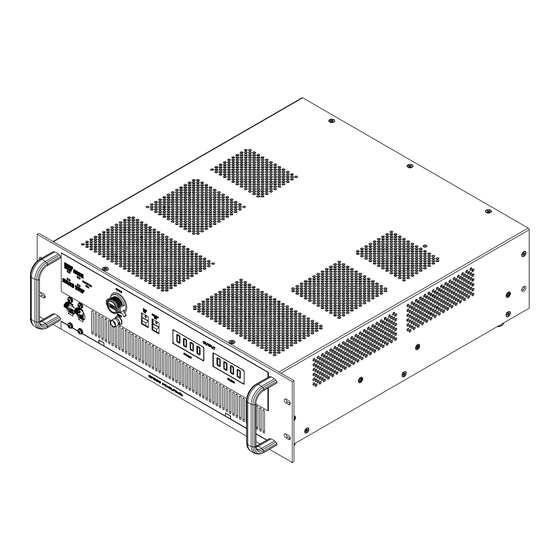
- Page 10 3044328 FIGURE 1-1. BOP 20-20H 400W POWER SUPPLY, D OPTION (DISPLAY/FRONT PANEL CONTROL) INSTALLED) BOP-H 042221...
-
Page 11: Section 1 - Introduction
SECTION 1 - INTRODUCTION SCOPE OF MANUAL This manual contains instructions for the installation and operation of the BOP-H Series of 400 Watt High Performance bipolar operational power supplies, hereafter referred to as BOP-H or simply BOP, manufactured by Kepco, Inc., Flushing, New York, U.S.A. -
Page 12: Secondary Options
1.2.2 SECONDARY OPTIONS There are six secondary options which are defined in the following paragraphs. Table 1-1 lists the combinations of secondary options as defined by a numerical suffix. TABLE 1-1. ADDITIONAL OPTION(S) INSTALLED Options installed Suffix 1.2.3 INDUCTIVE LOAD OPTIMIZATION (L OPTION): L Option models are stable handling heavy inductive loads (factory tests were performed with loads up to 1 Henry). -
Page 13: Dc Current Transformer (Dcct) (Z Option)
Z Option. GENERAL DESCRIPTION. Kepco Series BOP H Bipolar Power Supplies are linear stabilizers for laboratory and systems applications, able to operate in all four voltage-current quadrants, and able to pass smoothly through the zero point. -
Page 14: Electrical Specifications, General
ELECTRICAL SPECIFICATIONS, GENERAL See Table 1-2 for general specifications TABLE 1-2. GENERAL SPECIFICATIONS SPECIFICATION RATING/DESCRIPTION CONDITION/COMMENT Input Voltage (Nominal) 115/ 230Vrms Range: ±9% Rear panel selection Input Brown-out Voltage 104Vrms @ 115V/60Hz, Sourcing nominal output power Input Frequency (Nominal) 50/ 60Hz Range:±... - Page 15 TABLE 1-2. GENERAL SPECIFICATIONS (CONTINUED) SPECIFICATION RATING/DESCRIPTION CONDITION/COMMENT Voltage, Analog Programming Default values, for 10V programming (Voltage mode) signal: Change the gain/transfer factor by attaching resistors at the rear panel Gain/DC Transfer nom/10V/V or -E nom/10V/V, using Control/Access terminal block using a Factor a rear panel micro-switch screwdriver for a range of 0.1 to 10 (with...
- Page 16 TABLE 1-2. GENERAL SPECIFICATIONS (CONTINUED) SPECIFICATION RATING/DESCRIPTION CONDITION/COMMENT Analog Programming Input Type Differential The output can be controlled by the sum of analog and digital controls. See Max Voltage ±10V (differential), ±15V to signal ground/ Tables 2-1 and 2-6 for details. COM S Impedance 50k Ohms (differential),...
- Page 17 TABLE 1-2. GENERAL SPECIFICATIONS (CONTINUED) SPECIFICATION RATING/DESCRIPTION CONDITION/COMMENT Special Dynamic Configurations Preamplifier bandwidth 16kHz bandwidth, using rear panel To reduce total unit’s bandwidth in reduction switch, mode independent (see Table 2-2 voltage mode or current mode, attach for details). external capacitor to corresponding terminals of Control/Access terminal Main loop bandwidth Possible for both voltage and current by...
- Page 18 TABLE 1-2. GENERAL SPECIFICATIONS (CONTINUED) SPECIFICATION RATING/DESCRIPTION CONDITION/COMMENT Reference Voltages The reference voltages are available for external usage (for limits for example) at Value +10V, -10V the rear Analog Port (see Table 2-6 for details) Tolerance ±5mV Load Current 4mA max. Source Effect 0.0005% Load Effect...
- Page 19 TABLE 1-2. GENERAL SPECIFICATIONS (CONTINUED) SPECIFICATION RATING/DESCRIPTION CONDITION/COMMENT Rear panel All Options • AC inlet See Figure 2-2 and Table 2-2 for details. controls and • AC selector inputs • Output power terminals/busbars • Euro-block with: monitoring, sensing, grounding network, grounding, reducing bandwidth, changing gain/DC transfer factor terminals •...
- Page 20 TABLE 1-2. GENERAL SPECIFICATIONS (CONTINUED) SPECIFICATION RATING/DESCRIPTION CONDITION/COMMENT Series or Type of connection Master-Slave Parallel Implementation The cable KIT is universal, independent Each unit, master and all slaves, must configurations of model or series/parallel configuration, have the S-option installed (factory pre- (of identical without any changes to the units.
- Page 21 TABLE 1-2. GENERAL SPECIFICATIONS (CONTINUED) SPECIFICATION RATING/DESCRIPTION CONDITION/COMMENT Connections Source power 3-pin IEC connector Load connections, Rear: nickel plated copper busbars; GND Grounding, and GND NET on the above euro-block GND network terminals Analog control 14-pin euro-block terminals 15-pin D type female connector, Analog I/O port 8-pin phone jack, External control port 6-pin phone jack, External flag port...
-
Page 22: Miscellaneous Features
MISCELLANEOUS FEATURES 1.5.1 OUTPUT RANGE The BOP can be locally (front panel) adjusted, or remotely programmed, from (–)100% to (+)100% of its rated d-c or a-c peak voltage and current range. The Class AB bipolar output stage permits operation as either a source or a sink. (See Figure 1-2). Note that the BOP can not operate as a sink (quadrants II and IV, Figure 1-2) for long periods of time at full sink power, because the unit has a dissipative sink. -
Page 23: On-Off Feature
SINK SINK 3043440 SOURCE SOURCE FIGURE 1-3. BOP OUTPUT WAVEFORMS WITH PHASE SHIFT 1.5.3 ON-OFF FEATURE If the unit does not have a D-option, or if the D-option is installed, but the rear panel FP-RP switch is set to RP position, then the output can be turned ON or OFF by applying a signal at EXT CTRL Port pin 2 referenced to pin 8 (see Tables 2-2 and 2-4 for details). -
Page 24: Driving A Capacitive Load In Voltage Mode
CAUTION: When driving heavy inductive loads with high currents, it is possible for the BOP and the load to be damaged by a) an A-C input power loss, b) BOP fail- ure or c) external shutdown which prevents the load's stored energy from being dissipated inside the BOP. -
Page 25: Circuit Breaker Shutdown Prevention
1.5.6 CIRCUIT BREAKER SHUTDOWN PREVENTION Tripping of the front panel ON-OFF circuit breaker can be prevented when either input power is lost or the unit faults. However, because some faulting-errors are generated during a power off event, for the circuit breaker not to trip at power loss the rear panel YES - NO (CB@FAIL) switch has to be set to (or remain in) the default NO position. -
Page 26: External Voltage Monitor
NOTES: 1. Jumper wire between TB9 and TB10 (default, shown): G PREAMP = 1.005 ±0.02%. 2. If R ext_1 replaces jumper wire between TB9 and TB10: G PREAMP = ((10) (R ext_1 ) + (10000))/((1009.947) (R ext_1 ) + 9947)) For R ext_1 = 99k Ohms, G PREAMP = 0.1 (minimum allowed) 3. -
Page 27: Mode Control
1.5.12 MODE CONTROL The BOP is equipped with a rear panel-mounted VM - CM switch, active if the LOC - REM switch is set to LOC (local, default) position, which selects bipolar voltage or bipolar current mode operation. See Table 2-2, item 26 for details. With the rear LOC - REM switch set to REM (remote) position, the mode of operation can be set by a remote signal applied to EXT CTRL Port pin 5 referenced to pin 8 (see Figure 2-2, Table 2- 2 and Table 2-4 for details). -
Page 28: Front Panel Status Indications
FIGURE 1-5. BOUNDARIES AND LIMITS 1.5.15 FRONT PANEL STATUS INDICATIONS Refer to Figure 2-1 for the location of front panel terminations and controls and Table 2-1 for function details. 1.5.15.1 POWER (G)/FAULT (R)/LIMIT (O) INDICATOR The indicator lights green when the unit is operating properly and lights orange if the unit is in voltage or current limit mode. -
Page 29: Rear Panel Status Indications
TABLE 1-4. EQUIPMENT SUPPLIED ITEM PART NUMBER QUANTITY Source Power Entry mating connector. 142-0381 (Kepco) (IEC 320) Front panel INPUT mating connector 142-0599 (Kepco) Rear Panel EXT CTRL Port mating connector 142-0535 (Kepco Rear Panel EXT FLAG Port mating connector... -
Page 30: Accessories
PART NUMBER Power Cord Provides connection to 230V a-c mains via N6-20 plug, 118-1235 Mating Connector, Trigger Mates with Trigger port. 142-0527 (Kepco) SP2501 (CUI Stack) IEEE 1118 (BITBUS) Allows connection to IEEE 1118 (BITBUS) port. 142-0485 (Kepco) Mating connector KMDLA-5P (Kycon Inc.) -
Page 31: Safety
Service must be referred to authorized personnel. Using the power supply in a manner not specified by Kepco. Inc. may impair the protection provided by the power supply. Observe all safety precautions noted throughout this manual. Table 1-6 lists symbols used on the power supply or in this manual where applicable. -
Page 33: Mechanical Outline Drawing, Bop-H
FIGURE 1-6. MECHANICAL OUTLINE DRAWING, -22/(-23 BOP-H BOP-H 042221 1-23/(1-24 Blank) -
Page 35: Section 2 - Installation
SECTION 2 - INSTALLATION UNPACKING AND INSPECTION. This instrument has been thoroughly inspected and tested prior to packing and is ready for operation. After careful unpacking, inspect for shipping damage before attempting to operate. Perform the preliminary operational check as outlined in PAR. 2.6. If any indication of damage is found, file an immediate claim with the responsible transport service. - Page 36 TABLE 2-1. BOP FRONT PANEL TERMINATIONS AND CONTROLS (CONTINUED) FIG. 2-1 NAME OF TERMINATION FUNCTION INDEX NO. OR CONTROL POWER (G) Lights Green (G) when circuit breaker is on, AC voltage is present. and the unit FAULT (R) is functioning properly. LIMIT (O) Lights Red (R) when unit is faulted.
- Page 37 TABLE 2-1. BOP FRONT PANEL TERMINATIONS AND CONTROLS (CONTINUED) FIG. 2-1 NAME OF TERMINATION FUNCTION INDEX NO. OR CONTROL BIAS ON Installed with D Option (Display/front panel control) only. If switched on, pushbutton switch/indicator indicator lights green and bias established by DC BIAS pot is applied to programming input in use.
-
Page 38: Bop Terminations And Controls, Rear Panel
SEE DETAIL "C" SEE DETAIL "B" SEE DETAIL "A" SEE DETAIL "D" 2 3 4 RST/ AL0 - MUL PAR - SER MAS - SLA VM-CM MODEL BOP 20−20HD SER. NO. 1 - 0 (AD1) LOW-REG 1 - 0 (AD2) 1 - 0 (AD4) VLIM VCOR_A... - Page 39 Allows a-c source voltage to be applied to unit. Either 115V or 230V (±9%) inlet connector nominal per AC SELECTOR switch setting , 47-63Hz. IEC 320 mating connector. (Kepco P/N 142-0381) is supplied. Chassis Ground stud Provides chassis ground connection point.
- Page 40 TABLE 2-2. BOP REAR PANEL TERMINATIONS AND CONTROLS (CONTINUED) FIG. 2-2 NAME OF TERMINATION FUNCTION INDEX NO. OR CONTROL CAUTION: Turn unit off before changing any rear panel switch setting 1 - 0 AD1 microswitch Installed with S Option (Master/Slave) only. Used to set a unique binary address for units of a multiple system.
- Page 41 TABLE 2-2. BOP REAR PANEL TERMINATIONS AND CONTROLS (CONTINUED) FIG. 2-2 NAME OF TERMINATION FUNCTION INDEX NO. OR CONTROL CAUTION: Turn unit off before changing any rear panel switch setting USED FOR L/C OPTIONS Microswitch not connected for regular units without L, C or LC Options C OPT - REG If C Option installed: Used to enable C Option when set to C OPT or disable microswitch...
- Page 42 TABLE 2-2. BOP REAR PANEL TERMINATIONS AND CONTROLS (CONTINUED) FIG. 2-2 NAME OF TERMINATION FUNCTION INDEX NO. OR CONTROL CAUTION: Turn unit off before changing any rear panel switch setting TRIGGER Installed on G and E Option models only. May be used to initiate BOP output. input connector IEEE 1118 (BITBUS) PORT Installed on G and E Option models only.
- Page 43 TABLE 2-3. BOP CONTROL/ACCESS TERMINAL BLOCK FIG. 2-3 NAME OF SIGNAL FUNCTION INDEX NO. VCOR_A Used to connect a ceramic capacitor in the range of 1nF to 1uf, 50V, across terminals VCOR_A and VCOR_B to reduce the frequency bandwidth in voltage VCOR_B mode.
- Page 44 Input that enables the unit to shut-down/fail if the EXT CTRL connector is unplugged or if an external NC protection relay contact between pin 7 and pin 8 goes open. To activate this feature contact Kepco (change internal A1A1J9 floating jumper from 2+3 position to 1+2 position). After activating this feature, there must be less than 200 Ohms (or short circuit) between pin 7 and pin 8 for the unit not to fault.
- Page 45 3044331 FIGURE 2-5. BOP EXTL FLAG PORT TABLE 2-5. BOP EXTL FLAG PORT PIN ASSIGNMENTS FIG. 2-5 NAME OF SIGNAL FUNCTION INDEX NO. ON_FLAG Flag output signal indicates output ON or OFF status, Referenced to pin 6 (isolated 15V supply return, tied to chassis-GND), 15V CMOS compatible, 50sec response time, 5kVrms isolation vs output Output ON = logic 1 (+15V through 15k Ohms), Output OFF = logic 0 (saturated MOSFET transistor),...
- Page 46 3044332 FIGURE 2-6. BOP ANALOG PORT TABLE 2-6. BOP ANALOG PORT PIN ASSIGNMENTS FIG. 2-6 NAME OF SIGNAL FUNCTION INDEX NO. -10V -10V reference voltage; return at pin 9 N.C. Not Connected CMON Output current monitoring signal, 0 to ±10V for 0 to ± full scale nominal output current;...
-
Page 47: Factory Defaults
FACTORY DEFAULTS At the front panel, the factory default setting for the DC Bias dial is 500, and the locking lever is set to “unlocked” (right position). Factory settings for the rear panel microswitches and terminal jumpers are defined in Figure 2-7. VCOR_A VM-CM VCOR_B... - Page 48 Verify that the setup switches and jumpers at the rear panel are set to the factory default positions shown in Figure 2-7. This establishes the following default conditions: • Voltage Mode (VM) selected • Local Mode (LOC) - Voltage mode or current mode is determined by the rear panel VM - CM switch (27, Figure 2-2) •...
- Page 49 CAUTION: Make sure that terminals screws are tight and that OUT_S to OUT_M and COM_S to COM_M wire-links remained connected for local sensing. Set a-c circuit breaker/POWER switch (1, Figure 2-1) to ON. CAUTION: DO NOT repeatedly toggle the POWER on/off switch as this may cause unit to fault.
- Page 50 NOTE: Steps 5 through 13 below check Voltage Mode functions. Press the BIAS ON pushbutton switch (9, Figure 2-1) and verify that the inner indicator lights green. For a DC BIAS dial setting of 499 , both front panel voltmeter and external DVM show a voltage very close to zero (tolerance 0.5% of rating).
- Page 51 13. Return -VLIM pot to full CW position. Return the DC BIAS dial to read 499. Press OUTPUT OFF switch. Set a-c circuit breaker/POWER switch (1, Figure 2-1) to OFF. NOTE: Steps 14 through 28 below check Current Mode functions. 14.
- Page 52 16. Set a-c circuit breaker/POWER switch (1, Figure 2-1) to ON. CAUTION: DO NOT repeatedly toggle the POWER on/off switch as this may cause unit to fault. If actuator does not lock when released, wait a few seconds before trying again. The circuit breaker is “trip-free” - if overload exists, contacts cannot be held closed by actuator.
-
Page 53: Installation
The Chassis Slide Support Bars of the BOP are pre-drilled to accept Jonathan Series 110 QD slides. The slides listed in Table 2-7 can be accommodated. TABLE 2-7. CHASSIS SLIDE MOUNTING HOLES MOUNTING HOLES USED (SEE FIGURE 2-10) MODEL KEPCO P/N 110 QD-20-2 108-0067 110 QD-22-2 108-0156 110 QD-24-2... - Page 54 To install the slides, refer to Figure 2-10 and proceed as follows: Remove screws “A” through “E” from left and right chassis slide support bars. (Do not dis- card). Determine the required hole-pattern for the selected slide model from Table 2-7. Drill the “E”...
-
Page 55: Load Connection
NOTE: Observe polarities: the COMMON sensing wire must go to the COMMON load wire, the OUTPUT sensing wire must go to the OUTPUT load wire. NOTE: The following explanation of AC and DC grounding can apply to any Kepco power supply even though this text applies specifically to BOP Series. -
Page 56: D-C Ground
2.8.4 D-C GROUND Specified ripple and noise figures listed in Table 1-2 for operational power supplies are valid only with the COMMON side of the BOP output tied (by default) with a wire jumper to the GROUND- ING NETWORK and through this to an earth-ground point as shown in Figures 2-11 and 2-12. CAUTION: If the programming device return is tied to earth-ground, leave the BOP out- put floating. -
Page 57: Cooling
ACCESS/CONTROL SEE NOTE 2. TERMINAL BLOCK 4-POLE SWITCH OUTPUT COMMON RELAY COM_S 1.5k 0.5W COM_M NOTE 1. C x COM_S COM_M LOAD OUT_M GND_NET 1.5k OUT_M 0.5W OUT_S OUT_S NOTE 1. NOTES: For applications requiring very long connections to the load, additional external capacitors (C ) should be connected as shown to compensate for lead inductance of connecting wires. -
Page 58: Setting Up The Unit
2.10 SETTING UP THE UNIT The following paragraphs describe the connections and initial BOP setup needed to operate in the desired mode. 2.10.1 SETUP FOR ANALOG CONTROL With power off, configure the microswitches on the rear panel as follows (see Table 2-2 for details): Configure the mode of operation, voltage (VM) or current (CM), using the rear VM-CM switch (27, Figure 2-2), while the LOC-REM switch (28, Figure 2-2) is set to LOC. -
Page 59: Multiple Unit Configurations (S Option Required)
Configure the rear NO-YES (CB@P.LOSS) switch (39, Figure 2-2) to determine whether the input circuit breaker will trip upon input power loss. • YES (default) = input circuit breaker trips upon input power loss • NO = input circuit breaker does not trip upon input power loss. If this switch is set to NO, the YES-NO (CB@FAIL) switch (40, Figure 2-2) must also to be set to NO. -
Page 61: Section 3 - Operation
SECTION 3 - OPERATION INTRODUCTION BOP Bipolar Operational Power Supplies can be used in a great variety of applications. As a precision voltage or current source, the BOP-H output can be controlled locally (if the D Option is installed) by means of the front panel DC BIAS control or by a voltage signal applied to the front INPUT connector or by means of a voltage source or by a resistive type of control using the rear panel features, or by an optional digital interface (G or E Option). -
Page 62: Active Programming Sources
WARNING The COMMON output terminal of the BOP can be either grounded or floating, depending on the application. Additional precautions must be taken to make any user access to the output terminals impossible. The BOP must always have sensing configured. For voltage mode choose either local sensing (see PAR 2.8.1) or remote sensing (see PAR 2.8.2) as desired. -
Page 63: Simplified Application And Test Setup Requirements
• If S Option (Master/Slave) is installed, (see Table 2-2, items 16, 17, 18, 21, 22 and 23 to to configure the ALO - MUL, PAR - SER, MAS - SLA, AD1, AD2 and AD4 switches. • If L Option installed, see Table 2-2, item 36 to configure L-REG, switch. •... -
Page 64: Setting Current Limits
3.3.6 SETTING CURRENT LIMITS Current limits function when the unit operates in voltage mode to limit the output current to a user-defined value. Positive and negative current limits are independent and may be set to dif- ferent values. There are two methods of setting current limits, depending on whether the D Option (Display/front panel control) is installed. -
Page 65: Setting Voltage Limits
4. Set the unit to voltage mode by setting the rear panel VM-CM switch (27, Figure 2-2) to VM and set LOC-REM switch (28, Figure 2-2) to LOC (local operation). 5. Set the rear panel FP-RP switch (29, Figure 2-2) to RP. 6. -
Page 66: Setting Voltage Limits Without D Option
8. While monitoring the front panel OUTPUT DC VOLTS meter (11 Figure 2-1), adjust the rear panel –VLIM trimpot (35, Figure 2-2) to the desired negative voltage limit value. 9. Press front panel BIAS ON switch (9, Figure 2-1) for bias off (indicator not lit). 10. - Page 67 1. Program positive and negative voltage and current limit values (see PAR. 3.3.6 and 3.3.7). 2. Set AC POWER circuit breaker/switch (1, Figure 2-1) on the front panel to off. 3. Connect the load across the rear panel OUTPUT and COMMON terminals, using wires rated for the nominal output current;...
-
Page 68: Current Mode Operation With Voltage Limiting
3.3.9 CURRENT MODE OPERATION WITH VOLTAGE LIMITING. The BOP may be used as a stabilized (d-c) source of positive or negative current with output voltage limiting (for either polarity) pre-selected for the application at hand. The programming signal can be applied at either the front panel (if D Option is installed) or the rear panel. -
Page 69: Using The Bop As A Voltage Amplifier
8. Turn the output on (enabled) and off (disabled) from either the front panel (if D Option installed) or using a remote on-off signal. Front Panel (requires D Option). Set the rear panel FP-RP switch (29, Figure 2-2) to FP position then press the OUTPUT ON switch (10, Figure 2-1) as desired to turn the output on (switch lights green) or off (switch not lit). -
Page 70: Using The Bop As A Current Amplifier
3.3.11 USING THE BOP AS A CURRENT AMPLIFIER In order to amplify an external “current” signal ( I ext ), the signal must be converted into voltage, using a resistor (R b ) with a known value having a) a very low parasitic series inductance, b) a very low temperature coefficient and c) a power rating much higher than the its dissipation at maximum I ext value. -
Page 71: Section 4 - Calibration
SECTION 4 - CALIBRATION INTRODUCTION WARNING Hazardous voltage is present within the unit when powered on while the cover is removed. Removal of the cover is permitted only by autho- rized Service personnel. Cover removal is only needed if the top cover does not have cutouts to allow access to trimpots and test points. -
Page 72: Test Equipment Requirements
TOP VIEW, COVER REMOVED TEST EQUIPMENT REQUIREMENTS Table 4-2 lists sense resistors recommended for measuring current and includes Kepco and Manufacturer’s part numbers. The value of the sense resistor chosen should be known with 0.001% accuracy. If other than a recommended sense resistor is to be used, it must be rated for at least 100W power dissipation (actual power dissipation will be less than 10W). -
Page 73: Internal Adjustments And Calibrations
NOTE: Selected sense resistor must be mounted on a heatsink with a minimum surface area of 36 square inches to maintain ther- mal stability during calibration; forced cooling is recommended. Kepco Heatsink P/N 136-0451 will provide adequate cool- ing for the sense resistor. -
Page 74: Preamplifier Zero (A1A1R33)
4.3.2 PREAMPLIFIER ZERO (A1A1R33) This adjustment sets the output offset of the BOP preamplifier to zero. 1. Turn BOP off and configure the preamplifier: set amplification factor as desired, set the transfer factor sign either inverting or non-inverting. NOTE: Whenever Preamplifier configuration is changed, this Zero control R33 should be read- justed 2. -
Page 75: Output Voltage Zero Adjustment (A1A1R112)
4.3.4 OUTPUT VOLTAGE ZERO ADJUSTMENT (A1A1R112) This adjustment sets the output voltage offset to zero. 1. Turn off BOP. 2. Without a load connected to the BOP output, place a short circuit across the BOP input (at either the front panel INPUT twinax BNC type connector if D Option is installed or the rear panel Analog Port connector (13, Figure 2-2), pins 4 and 11.). -
Page 76: Output Current Full Scale Calibration (A1A1R72)
3. Set BOP to Current Mode. 4. Connect a precision current measuring shunt between BOP OUTPUT and COMMON output power terminals. 5. Connect DVM to the shunt's sensing terminals with the DVM return terminal connected to the same shunt sensing terminal that is connected to the BOP COMMON power terminal. 6. -
Page 77: Parallel Slave Output Current Reference Zero (A5R24)
4.4.1 PARALLEL SLAVE OUTPUT CURRENT REFERENCE ZERO (A5R24) This adjustment sets the offset of a parallel-connected Slave differential buffer circuit (used for the current reference coming from the master) to zero. 1. Turn off power to both master and slave BOP units. 2. -
Page 78: Series Slave Output Voltage Zero (A5R28)
9. Turn on both master and slave. Wait five minutes, then adjust A5R17 at the slave for 0A ± (0.00001 x I Onom 10. Turn off both master and slave. 4.4.3 SERIES SLAVE OUTPUT VOLTAGE ZERO (A5R28) This adjustment sets the offset of the Slave input circuit (used for the voltage reference coming from the master) to zero. -
Page 79: Section 5 - S Option - Series/Parallel Master/Slave
SECTION 5 - S OPTION - SERIES/PARALLEL MASTER/SLAVE INTRODUCTION Voltage sources, such as batteries, cells or stabilized d-c power supplies can be readily series- connected, but normally they can not be paralleled. Even small differences in their terminal potential would cause large, damaging, circulating currents. By complementary reasoning, cur- rent sources can easily be paralleled, but not series-connected. -
Page 80: Parallel Master/Slave Configurations
If all units have either the digital G or E Option installed and it is desired that the system be controlled digitally, then install an interconnection cable (consult Kepco) between the units' rear IEEE1118 ports; also set the rear address switches of the S-option as follows:... -
Page 81: Slave Initial Settings (Parallel)
Unless there are specific requirements for the transfer factor sign, leave the rear panel NON-INV rear switch in the NON (default) position for a positive transfer factor. Leave the rear panel LOW-REG switch in the REG (default) position for the regular (large frequency) bandwidth. -
Page 82: Local Sensing Connections (Parallel)
10. Set rear MAS-SLA switch to SLA (SLAve) position. 11. Set rear panel AD1, AD2 and AD4 switches to 0, however if the unit is under digital control (via G or E Option), set AD1 to 1. 12. At the rear panel terminal block leave wire links connecting OUT_S to OUT_M and COM_S to COM_M in place and remove the COM_M to GND_NET wire link (see Figure 5-1 for local sensing or Figure 5-2 for remote sensing. - Page 83 NOTE: Consult factory for configurations requiring more than two units in parallel. FIGURE 5-1. PARALLEL CONFIGURATION, LOCAL SENSING, TYPICAL BOP-H 042221...
-
Page 84: Remote Sensing Connections (Parallel)
5.3.4 REMOTE SENSING CONNECTIONS (PARALLEL) The following instructions are used to connect two units in a parallel master/slave configuration using remote sensing as shown in Figure 5-2. Perform steps 1 through 7 of PAR. 5.3.4 above. Verify that wire links between OUT_S and OUT_M (see 8, Figure 2-2) and between COM_S and COM_M on the master have been removed as specified in PAR. - Page 85 NOTE: Consult factory for configurations requiring more than two units in parallel. FIGURE 5-2. PARALLEL CONFIGURATION, REMOTE SENSING, TYPICAL BOP-H 042221...
-
Page 86: Series Master Slave Configurations
SERIES MASTER SLAVE CONFIGURATIONS 5.4.1 INITIAL MASTER SETTINGS (SERIES) Before connecting the two units in series, designate one unit as the Master and make the follow- ing initial settings as described below: If the Master has the D Option installed, then at the rear panel set FP-RP switch to FP (front panel) position for output on-off control from the front panel. -
Page 87: Initial Slave Settings (Series)
5.4.2 INITIAL SLAVE SETTINGS (SERIES) Before connecting the two units in series, designate one unit as the Slave and make the follow- ing initial settings as described below: If the Slave has the D Option installed, leave the DC BIAS switch set to OFF position. Do not apply any signal to the front panel INPUT connector. -
Page 88: Local Sensing Connections (Series)
5.4.3 LOCAL SENSING CONNECTIONS (SERIES) The following instructions are used to connect the two units in a series master/slave configura- tion using local sensing, as shown in Figure 5-3. At the master, install termination 195-0123 into MASTER SLAVE IN connector (15, Figure 2-2). - Page 89 NOTE: Consult factory for configurations requiring more than two units in series. FIGURE 5-3. SERIES CONFIGURATION, LOCAL SENSING, TYPICAL 5-11 BOP-H 042221...
-
Page 90: Remote Sensing Connections (Series)
5.4.4 REMOTE SENSING CONNECTIONS (SERIES) The following instructions are used to connect the two units in a series master/slave configura- tion using remote sensing, as shown in Figure 5-4. Perform steps 1 through 8 as specified in PAR. 5.4.3 above. Verify that wire links between COM_S and COM_M (see 8, Figure 2-2) on the Master have been removed. - Page 91 NOTE: Consult factory for configurations requiring more than two units in series. FIGURE 5-4. SERIES CONFIGURATION, REMOTE SENSING, TYPICAL 5-13 BOP-H 042221...
-
Page 92: Total Output Voltage And Current Of For Multiple Units
NOTE: Multiple unit configurations require that all individual units be properly calibrated. (Units shipped from Kepco have been factory-calibrated.) Refer to Section 4 to calibrate the individual units prior to connecting them in parallel or series. Using calibrated units ensures that the multiple unit configuration is calibrated. -
Page 93: S Option Calibration
S OPTION CALIBRATION Refer to PAR. 4.4 for S Option calibration. 5-15/(5-16 Blank) BOP-H 042221...
Need help?
Do you have a question about the BOP-H Series and is the answer not in the manual?
Questions and answers