Table of Contents
Advertisement
Quick Links
Advertisement
Table of Contents

Related Manuals for SIG Kadet Senorita EP


Summary of Contents for SIG Kadet Senorita EP
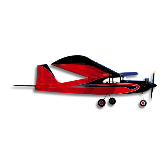
- Page 2 INTRODUCTION: ESC: 45A (minimum) Radio: 4 Channel with 4 Standard Servos Congratulations on your purchase of the new SIG KADET SENIORITA EP ARF kit! The Kadet Seniorita was originally RADIO EQUIPMENT: designed by Claude McCullough, following the same guidelines as...
-
Page 3: Required Tools
Two (2) 10-32 blind nuts installed for wing hold down. SIG Thin, Medium, and Thick CA Bag #6 Formed plastic cowl, trimmed, with four (4) pre-drilled SIG Fine Tip Applicator Tips for CA mounting holes SIG CA Debonder Sub bag 4 each T2.6 x 8 mm PWA mounting screws... -
Page 4: Wing Assembly
1 each 3 mm O.D. x 300 mm male nose gear steering Note that as received, the wing panels have the ailerons in place, pushrod but not yet permanently hinged. Hinging the ailerons will be done Sub bag A in the first few steps. To protect the covered parts of your model 1 each Pushrod connector with set screw and keeper from unnecessary damage, we suggest covering your work 2 each M2 x 24 mm threaded studs... - Page 5 Any excess glue drops or airborne battery pack into the battery receptacle in your receiver. smears can be quickly cleaned up using SIG CA Debonder. Be sure the aileron trim lever on the transmitter is in neutral. If...
-
Page 6: Fuselage Assembly
link to hold them firmly in place and suggest you do the same thing. Clamp the trailing edge of both ailerons in the neutral position to the wing panels as shown. Again, connect the two servo leads to the Y-harness and plug the harness into the aileron receptacle in When the extension connector is pulled through and out of the your receiver. - Page 7 tape. Like the ESC Velcro ® tape, we, again, suggest using medium or thick CA glue to secure the tape to the battery tray. 5) With the receiver now in place, the appropriate receiver connections can be made. Route the rudder and elevator servo leads up through the oval hole in the battery tray and plug the connectors into the rudder and elevator receiver receptacles.
-
Page 8: Landing Gear Installation
through the fuselage bottom at this location. Harden the pilot hole with a drop or two of thin CA glue. Establish the threads in the wood by screwing the PWA screw into the pilot hole and then remove it. Because the nylon landing gear strap must pivot on the screw, use a 5/32"... -
Page 9: Motor Installation
"flats" into the wheel axles, directly beneath the wheel collar setscrews. 5) The main landing gear and wheels are now installed. MOTOR INSTALLATION: As mentioned earlier in the MOTOR SELECTION section of this manual, you will now have to have your own motor and ESC available for the following steps. - Page 10 with its flat section directly over the nose gear steering arm. stabilizer saddle, at the top center. These openings will accept the mounting stubs at the bottom of the vertical fin. The third opening is the rudder pushrod slot on the left rear of the fuselage. Use a sharp #11 blade to neatly remove the covering material from these openings.
- Page 11 Also as shown, its location is 3/8" up from the bottom of the rudder onto the stabilizer. Use a sharp #11 blade to lightly cut and then, to the center of the horn. Align the four connection holes in the remove the covering from the bottom center section of the control horn arm with the hinge line.
-
Page 12: Pushrod Assembly & Installation
covering approximately 1/16" inside each of these two lines. 1) The rudder pushrod assembly is made first. This pushrod will require the 17" wood dowel, the 200 mm threaded one end wire pushrod and one of the 100 mm wire pushrods with an RC link at one end. - Page 13 to shrink it firmly over the wire and wood joint. Use the second fuselage, next to the fin. Pull the wire out of the slot far enough to piece of heat shrink tubing to cover and secure the opposite end straighten out the bend that was just made.
- Page 14 link to the steering arm. In the servo compartment, run the exposed end of the threaded stud into the hole in the pushrod connector. Center the nose wheel as closely as possible and tighten the setscrew in the pushrod connector. 8) Thread the M2 nut fully onto the exposed end of the stud.
- Page 15 3) Remove the spinner and propeller from the motor. Remove MOUNTING THE COWL, SPINNER, & PROPELLER: the cowl from the fuselage. "Harden" the four cowl mounting holes For the following steps, locate the following parts from the kit in the fuselage with a single small drop of thin CA glue in each contents: hole.
-
Page 16: Control Surface Travel
Carefully cut out the decal and lift it off of the sheet with tweezers. Use a product such as SIG Pure Magic Model Airplane Cleaner or A simple balancing fixture, such as two dowels with rubber tips to Windex ®... - Page 17 AN INSTRUCTOR CAN SAVE YOUR AIRPLANE! Without an experienced flight instructor on hand, it will most likely The SIG Kadet Seniorita EP ARF has been designed to fly as cause the loss of the model. easily as any trainer type model ever designed. The gentle flying...
- Page 18 Don't be discouraged if you have a minor crack-up. Just repair the After the airplane is trimmed to your liking and while still at altitude, damage and get back in the air, as soon as possible. throttle back completely to stop the motor and get a feel for the glide characteristics.
-
Page 19: Academy Of Model Aeronautics
AMA WEB SITE: www.modelaircraft.org CUSTOMER SERVICE SIG MANUFACTURING COMPANY, INC. is totally committed to your success in both assembling and flying the KADET SENIORITA EP ARF kit. Should you encounter any problem building this kit or discover any missing or damaged parts, please feel free to contact us by mail or telephone.
Need help?
Do you have a question about the Kadet Senorita EP and is the answer not in the manual?
Questions and answers