
Related Manuals for SMART Board M600i6


Summary of Contents for SMART Board M600i6
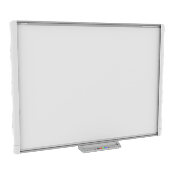
- Page 1 SMART Board® M600i6 Interactive whiteboard systems Configuration and user’s guide For models M680i6 and M685i6...
- Page 2 FCC warning This equipment has been tested and found to comply with the limits for a Class A digital device, pursuant to Part 15 of the US Federal Communications Commission Rules. These limits are designed to provide reasonable protection against harmful interference when the equipment is operated in a commercial environment. This equipment generates, uses and can radiate radio frequency energy and, if not installed and used in accordance with the manufacturer’s instructions, may cause harmful interference to radio communications.
-
Page 3: Important Information
Important information Before you install and use your SMART Board® M600i6 interactive whiteboard system, read and understand the safety warnings and precautions in this user’s guide and the important information document included. These safety warnings and precautions describe the safe and correct operation of your interactive whiteboard system and its accessories, helping you to prevent injuries and equipment damage. - Page 4 I M P O R T A N T I N F O R M A T I O N When mounting the projector boom on a framed or hollow wall, attach the mounting bracket to a stud to safely support the projector’s weight. If you use only drywall anchors, the drywall can fail, resulting in possible personal injury, and damage to the product which may not be covered by your warranty.
-
Page 5: Environmental Requirements
I M P O R T A N T I N F O R M A T I O N supply type. Do not climb (or allow children to climb) on a wall- or stand-mounted SMART Board interactive whiteboard. Do not climb on, hang from or suspend objects from the projector boom. Climbing on the interactive whiteboard or projector boom could result in personal injury or product damage. - Page 6 330 ohm, 150 pF probe (air discharge) Unmated connectors meet no malfunction or damage up to 4kV (both polarities) for direct (contact) discharge Cables All SMART Board M600i6 interactive whiteboard system cables should be shielded to prevent potential accidents and degraded video and audio quality. Conducted and...
-
Page 7: Table Of Contents
Contents Important information Safety warnings, cautions and important information Environmental requirements Chapter 1: About your interactive whiteboard system SMART Board M600i6 interactive whiteboard system features Included accessories Chapter 2: Installing your interactive whiteboard system Choosing a location Choosing a height Securing the projector to the boom... - Page 8 C O N T E N T S Appendix D: Remote control code definitions Appendix E: Hardware environmental compliance Waste Electrical and Electronic Equipment and Battery regulations (WEEE and Battery Directives) Batteries Mercury More information Index...
-
Page 9: Chapter 1: About Your Interactive Whiteboard System
Included accessories Remote control Pens Optional accessories Your SMART Board M600i6 interactive whiteboard system combines the following components: SMART Board M600 series interactive whiteboard Wall-mounted, short-throw SMART UF70 or SMART UF70w projector Accessories and optional equipment This chapter describes the features of your interactive whiteboard and provides information about... -
Page 10: Smart Board M600I6 Interactive Whiteboard System Features
DVD/Blu-ray™ players, VCRs, document cameras and digital cameras, and can project media from these sources onto the interactive screen. When you use SMART software with your SMART Board M600i6 interactive whiteboard system, you can write or draw over the projected computer image in digital ink using a pen tray pen or your finger, and then save these notes to a .notebook file or directly into any Ink Aware application. -
Page 11: Smart Uf70 Or Smart Uf70W Projector
C H A P T E R 1 About your interactive whiteboard system Other features of your interactive whiteboard include the following: Pen tray buttons that activate the pens’ colours and the on-screen keyboard, as well as right-click and Orientation functions A durable hard-coated surface that is optimised for projection and is easily cleaned For more information about your SMART Board... -
Page 12: Included Accessories
C H A P T E R 1 About your interactive whiteboard system Included accessories The following accessories are included with your interactive whiteboard system. Remote control The remote control enables you to control the system and set up your projector. Use the remote control to access menu options, system information and input selection options. -
Page 13: Chapter 2: Installing Your Interactive Whiteboard System
Installing SMART software I M P O R T A N T Use the SMART Board M600i6 interactive whiteboard system installation guide (smarttech.com/kb/170555) to install your interactive whiteboard and projector. This chapter provides additional considerations and details for installing your interactive whiteboard system. -
Page 14: Choosing A Height
Securing the projector to the boom To learn how to secure the SMART UF70 or SMART UF70w projector to the boom, see the SMART Board M600i6 interactive whiteboard system installation guide included (smarttech.com/kb/170555). Routeing the cables If your interactive whiteboard uses one mounting bracket, make sure that all projector cables pass along the top of the bracket and then down the side of the interactive whiteboard. -
Page 15: Installing Smart Software
C H A P T E R 2 Installing your interactive whiteboard system Installing SMART software You must install SMART software, such as SMART Meeting Pro™ software or SMART Notebook™ collaborative learning software on the computer connected to your interactive whiteboard system to access all of its features. Download SMART software from smarttech.com/software. -
Page 17: Chapter 3: Using Your Interactive Whiteboard System
Chapter 3 Using your interactive whiteboard system Using your projector Using your remote control Replacing the remote control battery Using the remote control buttons Adjusting projector settings Focusing the image Adjusting the image Projector connection diagram Using your interactive whiteboard This chapter describes the basic operation of your interactive whiteboard system and explains how to set up your remote control, retrieve system information, access the projector’s image adjustment options and integrate your interactive whiteboard system with peripheral devices. -
Page 18: Replacing The Remote Control Battery
C H A P T E R 3 Using your interactive whiteboard system Replacing the remote control battery Follow this procedure to replace the remote control battery. W A R N I N G Reduce the risk associated with a leaking battery in the projector’s remote control by following these practices: Use only the specified CR2025 coin-cell battery. -
Page 19: Using The Remote Control Buttons
C H A P T E R 3 Using your interactive whiteboard system Using the remote control buttons The projector remote control enables you to access on-screen menus and change projector settings. Use the Power button on the remote control to put the projector into Standby mode or to turn it on. -
Page 20: Adjusting Projector Settings
C H A P T E R 3 Using your interactive whiteboard system N O T E The Mute, Volume Up and Volume Down buttons work only if there is an audio source connected to the projector for the selected video input source. Adjusting projector settings The remote control’s Menu button enables you to access the on-screen display to adjust the projector settings. - Page 21 C H A P T E R 3 Using your interactive whiteboard system Setting Notes V-Position Moves the vertical position Don’t adjust this setting unless you’re advised of the source video up or to by SMART Support. down from -5 to 5 (relative to Apply this setting only after you make all boom the projected image).
- Page 22 C H A P T E R 3 Using your interactive whiteboard system Setting Notes Projector Functions menu Auto Signal Enables or disables signal The default is off. Detect searching of input Select On to have the projector continuously connectors. switch inputs until it finds an active video source.
- Page 23 C H A P T E R 3 Using your interactive whiteboard system Setting Notes Startup Screen Selects the type of startup This screen displays when the projector lamp screen (SMART, Capture is starting and a video source signal isn’t User Startup Screen, displayed.
- Page 24 C H A P T E R 3 Using your interactive whiteboard system Setting Notes IP Address Displays the projector’s To change the projector’s IP address, use the current IP address in values RS-232 connector (see Network information between 0.0.0.0 and on page 61) or use a DHCP server to assign a 255.255.255.255.
- Page 25 C H A P T E R 3 Using your interactive whiteboard system Setting Notes Contact Displays the contact name You can set the contact name or number using or number for projector the remote management features (see support as set by an Remotely managing your system through a administrator (maximum 16 network interface on page 41 and Remotely...
-
Page 26: Focusing The Image
Adjusting the image Refer to these notes when adjusting the projected image, as described in the SMART Board M600i6 interactive whiteboard system installation guide included (smarttech.com/kb/170555). Whilst adjusting the projected image size, shape and location, use the projector’s default background so that you can see the full projected image clearly. Don’t use other images, which might be cropped or scaled by the projector and could result in a misleading projected image size, shape and location. -
Page 27: Projector Connection Diagram
C H A P T E R 3 Using your interactive whiteboard system Projector connection diagram You can connect a variety of peripheral devices to your projector, including DVD/Blu-ray players, VCRs, document cameras, digital cameras and high-definition sources, as well as peripheral device outputs, such as a secondary projector or a flat-panel display and powered speakers. -
Page 28: Using Your Interactive Whiteboard
C H A P T E R 3 Using your interactive whiteboard system N O T E S To connect your interactive whiteboard, see the SMART Board M600i6 interactive whiteboard system installation guide (smarttech.com/kb/170555). To connect accessories to your interactive whiteboard, refer to the documents included with the accessories and consult the SMART Support website (smarttech.com/support) -
Page 29: Chapter 4: Maintaining Your Interactive Whiteboard System
Removing and replacing the projector lamp module Resetting the lamp hours This chapter includes methods for properly cleaning and preventing damage to your SMART Board M600i6 interactive whiteboard system. Maintaining your interactive whiteboard For information on maintaining your interactive whiteboard, see the SMART Board M600 interactive whiteboard installation guide (smarttech.com/kb/170555). -
Page 30: Cleaning The Projector
C H A P T E R 4 Maintaining your interactive whiteboard system The digital cameras located in the corners of the frame are protected from dust and dirt by windows. In extremely dusty environments, spray a proprietary household, alcohol-free glass cleaner onto a cotton swab and rub it gently on the windows. -
Page 31: Focusing And Adjusting The Projector Image
C H A P T E R 4 Maintaining your interactive whiteboard system I M P O R T A N T When cleaning the interactive whiteboard system: Wipe the exterior of the projector with a lint-free cloth. If necessary, use a soft cloth moistened with a mild detergent to clean the projector housing. - Page 32 C H A P T E R 4 Maintaining your interactive whiteboard system W A R N I N G smarttech.com/compliance for the projector’s MSDS documents. Replace the lamp module when the projector displays its lamp life warning message. If you continue to use the projector after this message appears, the lamp can shatter or burst, scattering glass throughout the projector.
- Page 33 C H A P T E R 4 Maintaining your interactive whiteboard system To remove the old lamp module 1. Press the Power button twice on the remote control to put the projector into Standby mode. 2. Wait at least 30 minutes for the projector to cool down. 3.
- Page 34 C H A P T E R 4 Maintaining your interactive whiteboard system To put the new lamp module into the projector 1. Remove the new lamp module from its packaging. 2. Carefully place the lamp module into the projector and gently press the power end of the lamp module against the projector to ensure that the power plug makes contact with the projector’s power port.
-
Page 35: Resetting The Lamp Hours
C H A P T E R 4 Maintaining your interactive whiteboard system Resetting the lamp hours Once you have replaced the lamp module, you need to access the projector service menu to reset the lamp hours. To prevent accidental errors, only a system administrator should perform this procedure. -
Page 37: Chapter 5: Troubleshooting Your Interactive Whiteboard System
Chapter 5 Troubleshooting your interactive whiteboard system Before you start Locating status lights Locating serial numbers Determining your interactive whiteboard system’s status Resolving interactive whiteboard issues Resolving operation issues Resolving projector issues Resolving projector errors Your projector stops responding The “Projector Overheated”, “Fan Failure”, “Lamp Failure” or “Colour Wheel Failure” message appears The “Lamp Failure”... -
Page 38: Before You Start
C H A P T E R 5 Troubleshooting your interactive whiteboard system This chapter provides basic troubleshooting information for your interactive whiteboard system. For issues not covered in this chapter, consult the SMART Support website (smarttech.com/support) or contact your authorised SMART reseller (smarttech.com/where). Before you start Before you troubleshoot your interactive whiteboard system or contact SMART Support or your authorised SMART reseller for assistance, you need to do the following:... -
Page 39: Determining Your Interactive Whiteboard System's Status
C H A P T E R 5 Troubleshooting your interactive whiteboard system The SMART UF70 and UF70w projector's serial number is located on the top of the projector. For the locations of serial numbers on other components and accessories, see smarttech.com/support. -
Page 40: Resolving Interactive Whiteboard Issues
C H A P T E R 5 Troubleshooting your interactive whiteboard system Pen tray Select Projected Touch and Status and related button status image pen control troubleshooting Projector Projector light Power light Service light Solid green None There’s an issue with the connections between the interactive whiteboard and the other components of the system. -
Page 41: Resolving Projector Issues
C H A P T E R 5 Troubleshooting your interactive whiteboard system Confirm that the USB cable is properly connected from a fully functional USB port on the computer to the interactive whiteboard. Resolving projector issues Resolving projector errors System administrators can resolve the following projector errors on their own prior to contacting SMART Support. -
Page 42: The "Lamp Failure" Message Appears
C H A P T E R 5 Troubleshooting your interactive whiteboard system The “Lamp Failure” message appears If the “Lamp Failure” message appears, one of the following issues is occurring: The lamp is overheating, likely due to blocked air vents. The lamp has reached the end of its life. -
Page 43: Loss Of Signal
C H A P T E R 5 Troubleshooting your interactive whiteboard system Ensure that the video source is properly connected to the projector. Press the Input button on the remote control or the Input Select button on the pen tray to switch to the correct video source. -
Page 44: Unstable Or Flickering Image
C H A P T E R 5 Troubleshooting your interactive whiteboard system To resolve a partial, scrolling or incorrectly displayed image on your Windows computer 1. Select Start > Control Panel. 2. Click Display and then select Adjust resolution. 3. -
Page 45: Frozen Image
Use the SMART Board M600i6 interactive whiteboard system installation guide (smarttech.com/kb/170555) to eliminate most image alignment issues. The projector image can slip if the projector is moved often or installed in a location prone to vibration, such as next to a heavy door. -
Page 46: Resolving Audio Issues
Make sure that there are no obstructions behind the projector’s wall-mounting bracket and that the bracket is firmly secured to the wall according to the installation instructions. Adjust the projected image. See the SMART Board M600i6 interactive whiteboard system installation guide (smarttech.com/kb/170555) and Adjusting the image on page 18. -
Page 47: Accessing The Service Menu
C H A P T E R 5 Troubleshooting your interactive whiteboard system 3. Press the Menu button and then select the Network Settings menu to check the IP address. See Adjusting projector settings on page 12 for a description of the IP address field. -
Page 48: Transporting Your Interactive Whiteboard System
C H A P T E R 5 Troubleshooting your interactive whiteboard system Resetting the projector At some point during troubleshooting, you might need to reset all projector settings. I M P O R T A N T This action is irreversible. To reset all projector settings 1. -
Page 49: Appendix A: Remotely Managing Your System Through A Network Interface
Simple Network Management Protocol (SNMP) This appendix includes detailed instructions on how to remotely manage your SMART Board M600i6 interactive whiteboard system settings through a network interface. Webpage management You can access advanced setup features via the projector’s webpage. This webpage enables you to manage the projector from a remote location using any computer connected to your intranet. -
Page 50: Accessing Webpage Management
A P P E N D I X A Remotely managing your system through a network interface Accessing webpage management Before you can access the webpage, connect your projector to the network and then enable the projector’s network functions using the projector’s menu. An IP address appears on the on- screen display. - Page 51 A P P E N D I X A Remotely managing your system through a network interface Submenu setting Description Mute Turns the mute settings on or off. Select On to mute the projector’s sound and Off to turn off mute. Volume Control Enables volume control.
- Page 52 A P P E N D I X A Remotely managing your system through a network interface Submenu setting Description Lamp Mode Adjusts lamp brightness to Standard or Economy. Standard displays a high-quality, bright image. Economy increases the lamp life by decreasing the brightness of the image. Auto Power Off Sets the length of the auto power off countdown timer between 1 and 240 minutes.
-
Page 53: Network Settings
A P P E N D I X A Remotely managing your system through a network interface Submenu setting Description High Speed Fan Adjusts the speed of the projector’s fan. Select High or Normal. N O T E Use the High setting when the projector’s temperature is high or the altitude is above 1800m (6000'). -
Page 54: Email Alerts
A P P E N D I X A Remotely managing your system through a network interface Submenu setting Description Gateway Displays or allows you to set the projector’s default network gateway in values between 0.0.0.0 and 255.255.255.255. Displays or allows you to set the projector’s IP address for your network’s primary domain name server in values between 0.0.0.0 and 255.255.255.255. -
Page 55: Password Settings
A P P E N D I X A Remotely managing your system through a network interface Submenu setting Description Displays or allows you to set the email address of the email alert “copy to” recipient. From Displays or allows you to set the email address of the user who sends the email alert. -
Page 56: Simple Network Management Protocol (Snmp)
A P P E N D I X A Remotely managing your system through a network interface Simple Network Management Protocol (SNMP) Your projector supports a list of SNMP commands as described in the management information base (MIB) file. You can download this file by browsing to smarttech.com/software and clicking the MIB file’s link in the Hardware section for the SMART UF70 projector. -
Page 57: Appendix B: Remotely Managing Your System Through An Rs-232 Serial Interface
Unknown command This appendix includes detailed instructions on how to set up your computer or room control system to remotely manage your SMART Board M600i6 interactive whiteboard system settings through an RS-232 serial interface. By connecting a computer or room control system to the interactive whiteboard, you can select video inputs, start up or shut down your interactive whiteboard system and request information such as projector lamp use, current settings and network addresses. -
Page 58: Serial Interface Settings
A P P E N D I X B Remotely managing your system through an RS-232 serial interface N O T E On projectors with the RS-232 connector labeled Control 9v (rather than Control), pin 1 functions as a +9V DC power source only for use with older model ECPs such as the ones shipped with SMART UF55 projectors. -
Page 59: Projector Programming Commands
A P P E N D I X B Remotely managing your system through an RS-232 serial interface 3. Configure your serial interface settings using the values from the table above and then press ENTER. An “invalid cmd= ? for help” message appears, and the “>” character appears as a command prompt on the following line. -
Page 60: Field Definitions
A P P E N D I X B Remotely managing your system through an RS-232 serial interface Field definitions Field Possible values Description This is an optional field. It forces the projector off option to shut down. Once this process starts, you can’t cancel it. -
Page 61: Field Definitions
A P P E N D I X B Remotely managing your system through an RS-232 serial interface Field definitions Field Possible values Description A text list of available video source inputs. current input VGA1 None is a non-selectable input and is returned Composite in response to a “get input”... -
Page 62: Video Control
A P P E N D I X B Remotely managing your system through an RS-232 serial interface > get videoinputs videoinputs = vga1, composite, hdmi1 > get usb1source usb1source = vga1 > get usb2source usb2source = hdmi1 > set usb2source=hdmi1 usb2source = hdmi1 >... - Page 63 A P P E N D I X B Remotely managing your system through an RS-232 serial interface set sharpness [target] sharpness=[current] get sharpness sharpness=[current] set hposition [target] hposition=[current] get hposition hposition=[current] set vposition [target] vposition=[current] get vposition vposition=[current] set whitepeaking [target] whitepeaking=[current] get whitepeaking whitepeaking=[current]...
-
Page 64: Field Definitions
A P P E N D I X B Remotely managing your system through an RS-232 serial interface Field definitions Field Possible values Description target displaymode The ranges must match the OSD ranges. = SMART Presentation = Bright room = Dark room = sRGB = User current displaymode... - Page 65 A P P E N D I X B Remotely managing your system through an RS-232 serial interface Field Possible values Description target sharpness The ranges must match the OSD ranges. + val – val = 0 to 31 current sharpness Range: 0 to 31 The ranges must match the OSD ranges.
- Page 66 A P P E N D I X B Remotely managing your system through an RS-232 serial interface Field Possible values Description target magenta The ranges must match the OSD ranges. + val – val = 0 to 100 current magenta Range: 0 to 100 The ranges must match the OSD ranges.
-
Page 67: Audio Control
A P P E N D I X B Remotely managing your system through an RS-232 serial interface E X A M P L E >set brightness = 65 brightness=65 >set brightness vga1 = 65 brightness vga1 = 65 This sets the brightness of the VGA1 source whether the projector is on this source or not. Audio control Use these commands to set audio output controls. -
Page 68: Field Definitions
A P P E N D I X B Remotely managing your system through an RS-232 serial interface Field definitions Field Possible values Description Use + or – to change the volume target volume + val incrementally. Enter a number within the range –... -
Page 69: Network Information
A P P E N D I X B Remotely managing your system through an RS-232 serial interface >set volume=-10 volume=-10 >set volume +5 volume=-5 >set volume -15 volume=-20 Network information Use these commands to set your network information. Command/response definitions Command Response Powered off... -
Page 70: Field Definitions
A P P E N D I X B Remotely managing your system through an RS-232 serial interface Field definitions Field Possible values Description current netstatus connected Current status of the network interface disconnected current network Current status of the network module and the VGA output target network Enable/Disable network module and VGA... - Page 71 A P P E N D I X B Remotely managing your system through an RS-232 serial interface Command Response Powered off get autosignal autosignal=[current] set lampreminder lampreminder= [target] [current] get lampreminder lampreminder= [current] set highbrightness highbrightness= [target] [current] get highbrightness highbrightness= [current] set autopoweroff...
- Page 72 A P P E N D I X B Remotely managing your system through an RS-232 serial interface Command Response Powered off get syshrs syshrs=[current] get resolution resolution=[current] get nativeaspectratio nativeaspect=[native] no get fwverddp fwverddp=[current] get fwvernet fwvernet=[current] get fwvermpu fwvermpu=[current] get serialnum serialnum=[current]...
-
Page 73: Field Definitions
A P P E N D I X B Remotely managing your system through an RS-232 serial interface Command Response Powered off emergencyalertmsg= emergencyalertmsg [current] [target] emergencyalertmsg= emergencyalertmsg [current] set emergencyalert emergencyalert= [target] [current] get emergencyalert emergencyalert= [current] get signaldetected signaldetected= The response varies depending on the power [current]... - Page 74 A P P E N D I X B Remotely managing your system through an RS-232 serial interface Field Possible values Description current zoom = 0 to 30 The ranges must match the OSD ranges. target projectorid + val The ranges must match the OSD ranges. –...
- Page 75 A P P E N D I X B Remotely managing your system through an RS-232 serial interface Field Possible values Description current reset done Sent once you reset the projector. current lamphrs 0 to 5000 Current lamp hour usage target lamphrs Clear the current lamp hour usage.
- Page 76 A P P E N D I X B Remotely managing your system through an RS-232 serial interface Field Possible values Description current language Arabic Must match the OSD setting Chinese (Simplified) Chinese (Traditional ) Czech Danish Dutch English Finnish French German Greek Letters...
-
Page 77: Service Information
A P P E N D I X B Remotely managing your system through an RS-232 serial interface Field Possible values Description current videomute Must match the OSD setting. target videomute = on Must match the OSD setting. = off current Status of VGA Out Enable and Network vgaoutnetenable... -
Page 78: Field Definitions
A P P E N D I X B Remotely managing your system through an RS-232 serial interface Command Response Powered off get error# error#=[current] set factoryreset factoryreset=[current] yes [target] set highspeedfan highspeedfan= [target] [current] get highspeedfan highspeedfan= [current] set statereporting statereporting= [target] [current]... - Page 79 A P P E N D I X B Remotely managing your system through an RS-232 serial interface Field Possible Values Description current failurelog normal Projector's error state. The modes are overtemp projector dependent. fanlock fanDMD fanblower fansystem lamperror colorwheelbreak lampignite lampoverheat lampdriver...
-
Page 80: Unknown Command
A P P E N D I X B Remotely managing your system through an RS-232 serial interface Field Possible Values Description A power override forces the projector to remain current poweroverride on when the command is received. This command isn’t persistent and isn’t stored to non-volatile memory (cleared on power cycle). -
Page 81: Appendix C: Integrating Other Devices
SMART UF70 projector SMART UF70w projector Connecting peripheral sources and outputs This appendix provides information on integrating your SMART Board M600i6 interactive whiteboard system with peripheral devices. Video format Your projector has a native video format and various video format compatibility modes. You can change image appearances for certain formats and compatibilities. -
Page 82: Smart Uf70 Projector
A P P E N D I X C Integrating other devices SMART UF70 projector Resolution Mode Aspect ratio Refresh rate Match Input (Hz) appearance 720 × 400 720×400_85 1.8:1 85.039 Letterbox 640 × 480 VGA 60 59.94 Full screen 640 × 480 VGA 72 72.809 Full screen... -
Page 83: Smart Uf70W Projector
A P P E N D I X C Integrating other devices SMART UF70w projector Resolution Mode Aspect Refresh Match Input Match Input ratio rate (Hz) appearance appearance (16:10 aspect (16:9 aspect ratio mode) ratio mode) 720 × 400 720×400_85 85.039 Letterbox Letterbox 640 ×... -
Page 84: Hd And Sd Signal Format Compatibility
A P P E N D I X C Integrating other devices HD and SD signal format compatibility The following tables list the projectors’ high definition (HD) and standard definition (SD) format signal compatibility, which the projector adjusts automatically when you use the aspect ratio commands described in Adjusting projector settings on page 12. -
Page 85: Connecting Peripheral Sources And Outputs
A P P E N D I X C Integrating other devices Video system signal compatibility The following tables list the projectors’ video system signal compatibility, particularly for signals delivered over S-Video and Composite video connectors, which the projector adjusts automatically when you use the aspect ratio commands described in Adjusting projector settings on page 12. - Page 86 A P P E N D I X C Integrating other devices To connect a peripheral source or output to your projector 1. Connect your peripheral device’s input cables to the projector. 2. Switch input sources to the peripheral device by pressing the Input button on the remote control.
-
Page 87: Appendix D: Remote Control Code Definitions
Appendix D Remote control code definitions IR signal format: NEC1 Repeat Vendor code Key code format Byte 1 Byte 2 Byte 3 Byte 4 Input Power ( ) Menu Up ( ) Left ( ) Enter ( ) Right ( ) Down ( ) Hide Volume up ( ) -
Page 89: Appendix E: Hardware Environmental Compliance
Appendix E Hardware environmental compliance SMART Technologies supports global efforts to ensure that electronic equipment is manufactured, sold and disposed of in a safe and environmentally friendly manner. Waste Electrical and Electronic Equipment and Battery regulations (WEEE and Battery Directives) Electrical and electronic equipment and batteries contain substances that can be harmful to the environment and to human health. -
Page 91: Index
Index 3.5mm audio connectors 19 electrostatic discharge iv email alerts 46 emergency alerts 45 emissions iv environmental requirements iii accessories included 4 optional 4 alarms 45 aspect ratios 14, 44, 73-74, 76-77 fans 33, 45 audio flickering 36 connections for 19 focus 18 controlling volume of 43 muting 11... - Page 92 S-video connections 77 SD signal compatibility 76 serial number 30 passwords 15, 39, 47 signal loss 35 pens 4 SMART Board interactive Perchlorate material 81 whiteboard See interactive whiteboard peripheral sources 77 SMART UF70 or UF70w pillarboxing 73-74, 76 projector See projector...
- Page 93 I N D E X temperatures, operating and storage iii transportation 40 TRAP destination address 46 troubleshooting 29 UF70 or UF70w projector See projector USB ports 19 UXGA support 73-74 VGA connections 19, 45 VGA support 73-74 video connections for 19 format compatibility for 73 warnings ii water and fluid resistance iii...
- Page 96 (Undefined variable: SMARTTrade- marks.Company_Long) smarttech.com/support smarttech.com/contactsupport...
Need help?
Do you have a question about the M600i6 and is the answer not in the manual?
Questions and answers