
Related Manuals for SMART Board M600ix3


Summary of Contents for SMART Board M600ix3
- Page 1 Help us make this document better smarttech.com/docfeedback/170910 SMART Board® M600ix3 interactive whiteboard systems CONFIGURATION AND USER’S GUIDE FOR MODELS M680ix3 AND M685ix3...
- Page 2 FCC warning This equipment has been tested and found to comply with the limits for a Class A digital device, pursuant to Part 15 of the FCC Rules. These limits are designed to provide reasonable protection against harmful interference when the equipment is operated in a commercial environment. This equipment generates, uses and can radiate radio frequency energy and, if not installed and used in accordance with the manufacturer’s instructions, may cause harmful interference to radio communications.
-
Page 3: Important Information
Important information Before you install and use the SMART Board® interactive whiteboard system, read and understand the safety warnings and precautions in this user’s guide and the included important information document. These safety warnings and precautions describe the safe and correct operation of the interactive whiteboard system and its accessories, helping you prevent injuries and equipment damage. - Page 4 CSA and/or UL Mark(s) for CSA/UL 60950. This is for operating safety and to avoid damage to the SMART Board interactive whiteboard. IMPORTANT Use the SMART Board M600ix3 interactive whiteboard system installation guide (smarttech.com/kb/170886) to install the interactive whiteboard and projector. Make sure an electrical socket is near the SMART product and remains easily accessible during use.
- Page 5 IMPORTANT INFORMATION Operation WARNING If you are using an external audio system, use only the power supply included with that product. Using the wrong power supply might create a safety hazard or damage the equipment. If in doubt, refer to the specification sheet for your product to verify the power supply type.
-
Page 6: Environmental Requirements
IMPORTANT INFORMATION Other precautions If you’re using a SMART product other than a SMART Board interactive whiteboard system, refer to the product’s installation manual for relevant warnings and maintenance instructions. Environmental requirements Before you install the SMART Board interactive whiteboard system, review the following environmental requirements. -
Page 7: Table Of Contents
Contents Important information Safety warnings, cautions and important information Environmental requirements Chapter 1: About the interactive whiteboard system SMART Board interactive whiteboard system features Included accessories Chapter 2: Installing the interactive whiteboard system Choosing a location Choosing a height Securing the projector to the boom Routing the cables Installing SMART software Chapter 3: Using the interactive whiteboard system... - Page 8 CONTENTS Appendix B: Remotely managing the system through an RS-232 serial interface Serial interface settings Projector programming commands Appendix C: Integrating other devices Video format Connecting peripheral sources and outputs Appendix D: Remote control code definitions Appendix E: Hardware environmental compliance Waste Electrical and Electronic Equipment and Battery regulations (WEEE and Battery Directives) Batteries...
-
Page 9: Chapter 1: About The Interactive Whiteboard System
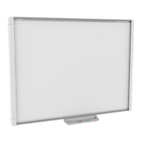
Chapter 1 About the interactive whiteboard system SMART Board interactive whiteboard system features SMART Board M600 series interactive whiteboard SMART U100 or SMART U100w projector Included accessories Remote control Pens Optional accessories The SMART Board interactive whiteboard system combines the following components: SMART Board M600 series interactive whiteboard Wall-mounted, short-throw SMART U100 or SMART U100w projector Accessories and optional equipment This chapter describes the features of the interactive whiteboard and provides information about... -
Page 10: Smart Board Interactive Whiteboard System Features
CHAPTER 1 ABOUT THE INTERACTIVE WHITEBOARD SYSTEM SMART Board interactive whiteboard system features Your SMART Board interactive whiteboard system uses the short-throw, high-offset SMART U100 or SMART U100w projector. When the projector displays an image from your computer on the touch- sensitive interactive whiteboard, you can do everything that you can do at your computer—open and close applications, scroll through files, conference with others, create new documents or... -
Page 11: Smart U100 Or Smart U100W Projector
CHAPTER 1 ABOUT THE INTERACTIVE WHITEBOARD SYSTEM Other features of your interactive whiteboard include the following: Pen tray buttons that activate the pens’ colors and the on-screen keyboard, as well as right- click and Orientation functions A durable hard-coated surface that is optimized for projection and is easily cleaned For more information about your SMART Board interactive whiteboard, see the SMART Board M600... -
Page 12: Included Accessories
CHAPTER 1 ABOUT THE INTERACTIVE WHITEBOARD SYSTEM An alert broadcast feature that enables administrators to send notification messages to network-connected projector systems for immediate on-screen display Protected cable routing through a cable cover that limits tampering and clutter A secure mounting and installation system that includes the following: An optional projector padlock ring to prevent removal of the projector from the boom Accessory mounting hardware for solid masonry or framed wall installations kit (Part Number 1007416) -
Page 13: Chapter 2: Installing The Interactive Whiteboard System
IMPORTANT Use the SMART Board M600ix3 interactive whiteboard system installation guide (smarttech.com/kb/170886) to install the interactive whiteboard and projector. This chapter provides additional considerations and details for installing the interactive whiteboard system. -
Page 14: Choosing A Height
CHAPTER 2 INSTALLING THE INTERACTIVE WHITEBOARD SYSTEM WARNING Refer to the interactive whiteboard system’s specifications (available at smarttech.com/support) for its weight. Check local building codes to ensure that the wall can support this weight, and use appropriate mounting hardware for the wall type. Choosing a height SMART includes a mounting template with each interactive whiteboard system. -
Page 15: Routing The Cables
CHAPTER 2 INSTALLING THE INTERACTIVE WHITEBOARD SYSTEM Routing the cables If the interactive whiteboard uses one mounting bracket, make sure that all projector cables pass along the top of the bracket and then down the side of the interactive whiteboard. If the interactive whiteboard uses two mounting brackets, make sure that all projector cables pass between the brackets. -
Page 17: Chapter 3: Using The Interactive Whiteboard System
Chapter 3 Using the interactive whiteboard system Using the projector Using the remote control Replacing the remote control battery Using the remote control buttons Adjusting projector settings Focusing the image Adjusting the image Projector connection diagram Using the interactive whiteboard This chapter describes the basic operation of the interactive whiteboard system and explains how to set up the remote control, retrieve system information, access the projector’s image adjustment options and integrate the interactive whiteboard system with peripheral devices. -
Page 18: Replacing The Remote Control Battery
CHAPTER 3 USING THE INTERACTIVE WHITEBOARD SYSTEM Replacing the remote control battery Follow this procedure to replace the remote control battery. WARNING Reduce the risk associated with a leaking battery in the projector’s remote control by following these practices: Use only the specified CR2025 coin-cell battery. Remove the battery when the remote control is unused for an extended period. -
Page 19: Using The Remote Control Buttons
CHAPTER 3 USING THE INTERACTIVE WHITEBOARD SYSTEM Using the remote control buttons The projector remote control enables you to access on-screen menus and change projector settings. Use the Power button on the remote control to put the projector into Standby mode or to turn it on. -
Page 20: Adjusting Projector Settings
CHAPTER 3 USING THE INTERACTIVE WHITEBOARD SYSTEM NOTE The Mute, Volume Up and Volume Down buttons work only if there is an audio source connected to the projector for the selected video input source. Adjusting projector settings Use the remote control’s Menu button to access the on-screen display and adjust the projector settings. - Page 21 CHAPTER 3 USING THE INTERACTIVE WHITEBOARD SYSTEM Setting Notes V-Position Moves the vertical position of Don’t adjust this setting unless you’re advised the source video up or down to by SMART Support. from -5 to 5 (relative to the Apply this setting only after you make all projected image).
- Page 22 CHAPTER 3 USING THE INTERACTIVE WHITEBOARD SYSTEM Setting Notes Color Opens a sub-menu for Each color has a default value of 100. adjusting the Red, Green, Blue, Adjustments to the color settings register Cyan, Magenta and Yellow under the User mode. colors on the projector from 0 to 100, providing custom color and luminance output.
- Page 23 CHAPTER 3 USING THE INTERACTIVE WHITEBOARD SYSTEM Setting Notes Color Opens a sub-menu for Each color has a default value of 100. adjusting the Red, Green, Blue, Adjustments to the color settings register Cyan, Magenta and Yellow under the User mode. colors on the projector from 0 to 100, providing custom color and luminance output.
- Page 24 CHAPTER 3 USING THE INTERACTIVE WHITEBOARD SYSTEM Setting Notes VGA1 Speaker Enables or disables the The default is on. speaker output while using the VGA1 input. HDMI1 Mic Enables or disables the The default is on. microphone input while using the HDMI1 input.
- Page 25 CHAPTER 3 USING THE INTERACTIVE WHITEBOARD SYSTEM Setting Notes Turns ImageCare on or off. The default is off. ImageCare Keystone Adjusts the size of the top and The default is 0. bottom edge with a range of Ensure that the top and bottom edges of the -15 to 15.
- Page 26 CHAPTER 3 USING THE INTERACTIVE WHITEBOARD SYSTEM Setting Notes Aspect Ratio Adjusts the image output to The default is Fill Screen. Fill Screen, Match Input or Fill Screen produces an image that fills the 16:9. entire screen by stretching and scaling the source video to match the projector’s native resolution and aspect ratio.
- Page 27 CHAPTER 3 USING THE INTERACTIVE WHITEBOARD SYSTEM Setting Notes Default Opens the Reset to Default If you select Yes, all projector settings reset screen, in which the user can to their defaults, reversing any menu changes resets the projector settings to you made.
- Page 28 CHAPTER 3 USING THE INTERACTIVE WHITEBOARD SYSTEM Setting Notes Displays the projector’s domain name server IP address in values between 0.0.0.0 and 255.255.255.255. MAC Address Displays the projector’s MAC address in xx-xx-xx-xx-xx-xx format. Group Name Displays the projector’s You can set the projector’s workgroup name workgroup name as set by an using the remote management features (see Remotely managing the system through a...
- Page 29 CHAPTER 3 USING THE INTERACTIVE WHITEBOARD SYSTEM Setting Notes Language menu Language Selects the language used in Projector menu support is available in English the projector menus. (U.S.), English (UK) French, German, Dutch, Danish, Finnish, Italian, Norwegian, Russian, Spanish, Swedish, Portugese, Chinese (Simplified), Chinese (Traditional), Czech, Hungarian, Japanese, Malayasian, Polish, Romanian, Arabic, Turkish, Greek, Slovak,...
-
Page 30: Focusing The Image
CHAPTER 3 USING THE INTERACTIVE WHITEBOARD SYSTEM Setting Notes Model Number Displays the projector’s model number (SMART U100 or SMART U100w). Serial Number Displays the projector’s serial number. Focusing the image Use the projector’s focus slider to focus the projected image. To focus the image Adjust the Focus slider until the image is in focus. -
Page 31: Adjusting The Image
USING THE INTERACTIVE WHITEBOARD SYSTEM Adjusting the image Refer to these notes when adjusting the projected image, as described in the included SMART Board M600ix3 interactive whiteboard system installation guide (smarttech.com/kb/170886). While adjusting the projected image size, shape and location, use the projector’s default background so that you can see the full projected image clearly. - Page 32 CHAPTER 3 USING THE INTERACTIVE WHITEBOARD SYSTEM Connector Connect to: USB B Computer (for service access only) DB15F (DE-15F) RGB video output (VGA Secondary display (not included) Out) DB15F (DE-15F) RGB video input (VGA1) Primary computer (not included) RCA Composite video input Video source (not included) HDMI1 and HDMI2 inputs High-definition video and audio sources...
-
Page 33: Using The Interactive Whiteboard
CHAPTER 3 USING THE INTERACTIVE WHITEBOARD SYSTEM NOTES To connect the interactive whiteboard, see the SMART Board M600ix3 interactive whiteboard system installation guide (smarttech.com/kb/170886). To connect accessories to the interactive whiteboard, refer to the documents included with the accessories and consult the SMART Support website (smarttech.com/support) for additional information. -
Page 35: Chapter 4: Maintaining The Interactive Whiteboard System
Chapter 4 Maintaining the interactive whiteboard system Maintaining the interactive whiteboard Preventing damage to the interactive whiteboard Keeping the writing surface clean Cleaning the projector Focusing and adjusting the projector image Replacing the projector lamp Removing and replacing the projector lamp module Resetting the lamp hours This chapter includes methods for properly cleaning and preventing damage to the SMART Board interactive whiteboard system. -
Page 36: Cleaning The Projector
CHAPTER 4 MAINTAINING THE INTERACTIVE WHITEBOARD SYSTEM Don’t use abrasive erasers or harsh chemicals to clean the product. The digital cameras located in the corners of the frame are protected from dust and dirt by windows. In extremely dusty environments, spray an alcohol-free household glass cleaner, such as Windex®... -
Page 37: Focusing And Adjusting The Projector Image
CHAPTER 4 MAINTAINING THE INTERACTIVE WHITEBOARD SYSTEM Do not spray cleaners, solvents or compressed air directly on the projector. Do not use spray cleaners or solvents near any part of the projector because they can damage or stain the unit. Spraying the system could spread a chemical mist on some of the projector’s components and lamp, resulting in damage and poor image quality. - Page 38 CHAPTER 4 MAINTAINING THE INTERACTIVE WHITEBOARD SYSTEM WARNING smarttech.com/compliance for the projector’s MSDS documents. Replace the lamp module when the projector displays its lamp life warning message. If you continue to use the projector after this message appears, the lamp can shatter or burst, scattering glass throughout the projector.
- Page 39 CHAPTER 4 MAINTAINING THE INTERACTIVE WHITEBOARD SYSTEM When replacing the projector lamp module: Put the projector into Standby mode and wait 30 minutes for the lamp to cool completely. Do not loosen or remove any screws other than those specified in the lamp replacement instructions.
- Page 40 CHAPTER 4 MAINTAINING THE INTERACTIVE WHITEBOARD SYSTEM 4. Open the lamp cover. 5. Use a Phillips screwdriver to loosen the two captive screws from the bottom of the lamp module. NOTE Don’t try to remove these screws. Captive screws can’t be removed, only loosened. 6.
- Page 41 CHAPTER 4 MAINTAINING THE INTERACTIVE WHITEBOARD SYSTEM 7. Remove the lamp module smarttech.com/kb/170910...
- Page 42 CHAPTER 4 MAINTAINING THE INTERACTIVE WHITEBOARD SYSTEM To put the new lamp module into the projector 1. Remove the new lamp module from its packaging. 2. Carefully place the lamp module into the projector and gently press the power end of the lamp module against the projector to ensure the power plug makes contact with the projector’s power receptacle.
- Page 43 CHAPTER 4 MAINTAINING THE INTERACTIVE WHITEBOARD SYSTEM 3. Use the Phillips screwdriver to secure the captive screws. IMPORTANT Do not over-tighten the screws. 4. Close the lamp cover. 5. Connect the power cable to the wall outlet. 6. Press the Power button once on the remote control to confirm that the projector is operating and that the lamp module is correctly installed.
-
Page 44: Resetting The Lamp Hours
CHAPTER 4 MAINTAINING THE INTERACTIVE WHITEBOARD SYSTEM Resetting the lamp hours After you replace the lamp module, access the projector service menu to reset the lamp hours. To prevent errors, only a system administrator should perform this procedure. NOTE Always reset the lamp hours after you replace the lamp, because lamp service reminders are based on the current hours of use. -
Page 45: Chapter 5: Troubleshooting The Interactive Whiteboard System
Chapter 5 Troubleshooting the interactive whiteboard system Before you start Locating status lights Locating serial numbers Determining the interactive whiteboard system’s status U100 and U100w projector status lights Resolving interactive whiteboard issues Resolving operation issues Resolving projector errors The projector stops responding The “Lamp Failure”... -
Page 46: Before You Start
CHAPTER 5 TROUBLESHOOTING THE INTERACTIVE WHITEBOARD SYSTEM This chapter provides basic troubleshooting information for the interactive whiteboard system. For issues not covered in this chapter, consult the SMART Support website (smarttech.com/support) or contact your authorized SMART reseller (smarttech.com/where). Before you start Before you troubleshoot the interactive whiteboard system or contact SMART Support or your authorized SMART reseller for assistance, you need to do the following: Locate the interactive whiteboard system’s status lights. -
Page 47: Determining The Interactive Whiteboard System's Status
CHAPTER 5 TROUBLESHOOTING THE INTERACTIVE WHITEBOARD SYSTEM Locating serial numbers The SMART Board M600 interactive whiteboard serial number is located on the lower-right edge of the frame, as well as on the back of the interactive whiteboard. For more information, see the SMART Board M600 series interactive whiteboard user’s guide (smarttech.com/kb/170410). -
Page 48: U100 And U100W Projector Status Lights
CHAPTER 5 TROUBLESHOOTING THE INTERACTIVE WHITEBOARD SYSTEM Pen tray Select Projected image Touch and pen Status and related troubleshooting button status light control Projector Power Projector Service light light Flashing amber None None The system is entering Standby mode. Solid green Solid amber None The interactive whiteboard’s... - Page 49 CHAPTER 5 TROUBLESHOOTING THE INTERACTIVE WHITEBOARD SYSTEM Lamp state Power LED Projector Diagnostic Description Remedy Service light Indicator Solid green Solid red Lh = Lamp hours reminder Order a new lamp soon. After the projector starts, a message appears on-screen telling the user to replace the lamp soon.
-
Page 50: Resolving Interactive Whiteboard Issues
CHAPTER 5 TROUBLESHOOTING THE INTERACTIVE WHITEBOARD SYSTEM Resolving interactive whiteboard issues This section includes information on resolving issues with the interactive whiteboard. For information not covered in this section, see the SMART Board M600 series interactive whiteboard user’s guide (smarttech.com/kb/170410). Resolving operation issues To resolve operation issues, complete the following tasks: Confirm that all cables are securely connected to the back of the pen tray, computer and control module. -
Page 51: Resolving Image Issues
CHAPTER 5 TROUBLESHOOTING THE INTERACTIVE WHITEBOARD SYSTEM The “Lamp Failure” message appears If the “Lamp Failure” message appears, one of the following issues is occurring: The lamp is overheating, likely due to blocked air vents. The lamp has reached the end of its life. The projector has an internal problem. -
Page 52: Loss Of Signal
CHAPTER 5 TROUBLESHOOTING THE INTERACTIVE WHITEBOARD SYSTEM Press the Input button on the remote control or the Input Select button on the pen tray to switch to the correct video source. If these tasks don’t resolve the issue, refer to the following sections for additional troubleshooting information. -
Page 53: Unstable Or Flickering Image
CHAPTER 5 TROUBLESHOOTING THE INTERACTIVE WHITEBOARD SYSTEM To resolve a partial, scrolling or incorrectly displayed image on a Windows computer 1. Select Start > Control Panel. 2. Click Display, and then select Adjust resolution. 3. Verify that the display resolution is set to 1024 × 768 (SMART U100 projector) or 1280 × 800 (SMART U100w projector in 16:10 aspect ratio mode). -
Page 54: Frozen Image
CHAPTER 5 TROUBLESHOOTING THE INTERACTIVE WHITEBOARD SYSTEM 4. Optionally, reset the projector as described in Resetting the projector on page 49 to adjust the frequency and tracking to their original values. IMPORTANT This action resets all values to their defaults. Frozen image If the projector has a frozen image, perform the following procedure. -
Page 55: Resolving Audio Issues
Use the instructions in the SMART Board M600ix3 interactive whiteboard system installation guide (smarttech.com/kb/170886) to eliminate most image alignment issues. The projector image can slip if the projector is moved often or installed in a location prone to vibration, such as next to a heavy door. -
Page 56: Resolving Network Communication Issues
CHAPTER 5 TROUBLESHOOTING THE INTERACTIVE WHITEBOARD SYSTEM 5. Check that the source input, such as your computer or video device, isn’t malfunctioning. Ensure that its audio output is on and that the volume isn’t set to the lowest position. NOTE You must display the source input’s video to play its audio through the connected speakers or audio system. -
Page 57: Transporting The Interactive Whiteboard System
CHAPTER 5 TROUBLESHOOTING THE INTERACTIVE WHITEBOARD SYSTEM Retrieving your password If you forget the projector’s password, you can retrieve it by accessing the projector service menu directly from the projector or from the password settings menu on the projector’s web interface (see Password settings on page 58). -
Page 59: Appendix A: Remotely Managing The System Through A Network Interface
Appendix A Remotely managing the system through a network interface Web page management Accessing web page management Home Control panel Network settings Email alerts Password settings Simple Network Management Protocol (SNMP) This chapter includes detailed instructions on how to remotely manage the SMART Board interactive whiteboard system settings through a network interface. -
Page 60: Accessing Web Page Management
APPENDIX A REMOTELY MANAGING THE SYSTEM THROUGH A NETWORK INTERFACE Accessing web page management Before you can access the web page, connect the projector to the network and enable the projector’s network functions using the projector’s menu. An IP address appears on the on-screen display. - Page 61 APPENDIX A REMOTELY MANAGING THE SYSTEM THROUGH A NETWORK INTERFACE Submenu setting Description Restore All Projector Returns projector settings to default values or refreshes the current Defaults settings. Select Submit or Refresh. IMPORTANT The Submit option is irreversible and resets all values. Volume Adjusts the projector’s volume from 0 to 40.
- Page 62 APPENDIX A REMOTELY MANAGING THE SYSTEM THROUGH A NETWORK INTERFACE Submenu setting Description Lamp Reminder Select On to show or Off to hide the lamp replacement reminder when it appears. This reminder appears 100 hours before the recommended lamp replacement. Lamp Mode Adjusts lamp brightness to Normal or ECO.
-
Page 63: Network Settings
APPENDIX A REMOTELY MANAGING THE SYSTEM THROUGH A NETWORK INTERFACE Submenu setting Description Video Mute Turns the video mute setting on or off. Select On to hide the display and Off to show it again. High Speed Fan Adjusts the speed of the projector’s fan. Select High or Normal. NOTE Use the High setting when the projector’s temperature is high or the altitude is above 6000' (1800 m). - Page 64 APPENDIX A REMOTELY MANAGING THE SYSTEM THROUGH A NETWORK INTERFACE Submenu setting Description IP Address Displays or allows you to set the projector’s IP address in values between 0.0.0.0 and 255.255.255.255. Subnet Mask Displays or allows you to set the projector’s subnet mask number in values between 0.0.0.0 and 255.255.255.255.
-
Page 65: Email Alerts
APPENDIX A REMOTELY MANAGING THE SYSTEM THROUGH A NETWORK INTERFACE Email alerts This menu enables you to enter your preferred address for receiving email alerts and to adjust related settings. Submenu setting Description Email Alert Select Enable to turn on or Disable to turn off the email alert function. -
Page 66: Password Settings
APPENDIX A REMOTELY MANAGING THE SYSTEM THROUGH A NETWORK INTERFACE Submenu setting Description Alert Condition Sends email alerts whenever the following conditions occur. Select the settings you want, and then click Submit. Lamp Hours Reminder Lh System Fan 1 Fail F1 System Fan 2 Fail F2 System Fan 3 Fail F3 Blower Fan Fail F4... -
Page 67: Simple Network Management Protocol (Snmp)
APPENDIX A REMOTELY MANAGING THE SYSTEM THROUGH A NETWORK INTERFACE NOTES The first time you enable the password settings, the default password value is four numbers, for example, 1234. The maximum allowable password length is four numbers or letters. If you forget the projector password, refer to Accessing the service menu on page 48 to set the projector setting to factory defaults. -
Page 69: Appendix B: Remotely Managing The System Through An Rs-232 Serial Interface
Appendix B Remotely managing the system through an RS-232 serial interface Serial interface settings Projector programming commands Projector power state controls Command/response definitions Field definitions Source Application Selection Command/response definitions Field definitions Video control Command/response definitions Field definitions Audio control Command/response definitions Field definitions Network information... -
Page 70: Serial Interface Settings
APPENDIX B REMOTELY MANAGING THE SYSTEM THROUGH AN RS-232 SERIAL INTERFACE This appendix includes detailed instructions on how to set up your computer or room control system to remotely manage the SMART Board interactive whiteboard system settings through an RS-232 serial interface. By connecting a computer or room control system to the interactive whiteboard, you can select video inputs, start up or shut down the interactive whiteboard system and request information such as projector lamp use, current settings and network addresses. -
Page 71: Projector Programming Commands
APPENDIX B REMOTELY MANAGING THE SYSTEM THROUGH AN RS-232 SERIAL INTERFACE 3. Configure the serial interface settings using the values from the table above, and then press ENTER. An “invalid cmd= ? for help” message appears, and the “>” character appears as a command prompt on the following line. -
Page 72: Field Definitions
APPENDIX B REMOTELY MANAGING THE SYSTEM THROUGH AN RS-232 SERIAL INTERFACE Field definitions Field Possible values Description off option This is an optional field. It forces the projector to shut down. Once this process starts, it can’t be canceled. If “now” isn’t specified, the “off” command causes a countdown to appear. -
Page 73: Field Definitions
APPENDIX B REMOTELY MANAGING THE SYSTEM THROUGH AN RS-232 SERIAL INTERFACE Field definitions Field Description Possible values current input VGA1 A text list of available video source inputs. None is a non-selectable input and is returned Composite in response to a “get input” command when the HDMI1 projector is turned off. -
Page 74: Video Control
APPENDIX B REMOTELY MANAGING THE SYSTEM THROUGH AN RS-232 SERIAL INTERFACE EXAMPLE > set input=vga1 input = vga1 > set input=next input = composite > get videoinputs videoinputs = vga1, composite, hdmi1 > get usb1source usb1source = vga1 > get usb2source usb2source = hdmi1 >... - Page 75 APPENDIX B REMOTELY MANAGING THE SYSTEM THROUGH AN RS-232 SERIAL INTERFACE get saturation saturation=[current] set tint [target] tint=[current] get tint tint=[current] set sharpness [target] sharpness=[current] get sharpness sharpness=[current] set hposition [target] hposition=[current] get hposition hposition=[current] set vposition [target] vposition=[current] get vposition vposition=[current] set whitepeaking [target] whitepeaking=[current]...
-
Page 76: Field Definitions
APPENDIX B REMOTELY MANAGING THE SYSTEM THROUGH AN RS-232 SERIAL INTERFACE set displayhide displayhide= [target] get displayhide displayhide= [target] Field definitions Field Possible values Description target displaymode The ranges must match the OSD ranges. = SMART Presentation = Bright room = Dark room = sRGB = User... - Page 77 APPENDIX B REMOTELY MANAGING THE SYSTEM THROUGH AN RS-232 SERIAL INTERFACE Field Possible values Description target saturation The ranges must match the OSD ranges. + val – val = 0 to 100 current saturation Range: 0 to 100 The ranges must match the OSD ranges. target tint The ranges must match the OSD ranges.
- Page 78 APPENDIX B REMOTELY MANAGING THE SYSTEM THROUGH AN RS-232 SERIAL INTERFACE Field Possible values Description target green The ranges must match the OSD ranges. + val – val = 0 to 100 current green Range: 0 to 100 The ranges must match the OSD ranges. target blue The ranges must match the OSD ranges.
-
Page 79: Audio Control
APPENDIX B REMOTELY MANAGING THE SYSTEM THROUGH AN RS-232 SERIAL INTERFACE Use the above commands to set the property to an absolute value or to adjust the current value. EXAMPLE >get brightness brightness=55 >set brightness = 65 brightness=65 >set brightness +5 brightness=70 >set brightness -15 brightness=55... -
Page 80: Field Definitions
APPENDIX B REMOTELY MANAGING THE SYSTEM THROUGH AN RS-232 SERIAL INTERFACE Command Response Powered off set volumecontrol volumecontrol= [target] [current] get volumecontrol volumecontrol= [current] set cc [target] cc=[current] get cc cc=[current] set sysoutputsw sysoutputsw=[current] [target] get sysoutputsw sysoutputsw=[current] Field definitions Field Possible values Description... - Page 81 APPENDIX B REMOTELY MANAGING THE SYSTEM THROUGH AN RS-232 SERIAL INTERFACE Field Possible values Description current volumecontrol = on Current state of the volume control = off target volumecontrol = on Specifies whether volume control is enabled or = off disabled.
-
Page 82: Network Information
APPENDIX B REMOTELY MANAGING THE SYSTEM THROUGH AN RS-232 SERIAL INTERFACE Network information Use these commands to set your network information. Command/response definitions Command Response Powered off get netstatus netstatus=[current] set network network=[current] get network network=[current] set dhcp [target] dhcp=[current] get dhcp dhcp=[current] set ipaddr [target]... -
Page 83: System Information
APPENDIX B REMOTELY MANAGING THE SYSTEM THROUGH AN RS-232 SERIAL INTERFACE Field Possible values Description current dhcp = on Enable/Disable for DHCP Networking = off target dhcp Enable/Disable for DHCP Networking Range: 0.0.0.0 to current ipaddr Current IP address (static or dhcp assigned) 255.255.255.255 = Range: 0.0.0.0 to target ipaddr... - Page 84 APPENDIX B REMOTELY MANAGING THE SYSTEM THROUGH AN RS-232 SERIAL INTERFACE Command Response Powered off set lampmode [target] lampmode=[current] get lampmode lampmode=[current] set ImageCare [target] ImageCare=[current] get ImageCare ImageCare=[current] set autopoweroff autopoweroff=[current] no [target] get autopoweroff set autopoweroff=[current] no zoom [target] set zoom [target] zoom=[current] get zoom...
- Page 85 APPENDIX B REMOTELY MANAGING THE SYSTEM THROUGH AN RS-232 SERIAL INTERFACE Command Response Powered off get serialnum serialnum=[current] get fwverecp fwverecp=[current] set language [target] language=[current] get language language=[current] set groupname [target] groupname=[current] get groupname groupname=[current] set projectorname projectorname= [target] [current] get projectorname projectorname= [current]...
-
Page 86: Field Definitions
APPENDIX B REMOTELY MANAGING THE SYSTEM THROUGH AN RS-232 SERIAL INTERFACE Field definitions Field Possible values Description target autosignal = on The ranges must match the OSD settings. = off current autosignal The ranges must match the OSD settings. target lampreminder = on The ranges must match the OSD settings. - Page 87 APPENDIX B REMOTELY MANAGING THE SYSTEM THROUGH AN RS-232 SERIAL INTERFACE Field Possible values Description current projectorid = 0 to 999 The ranges must match the OSD ranges. target aspectratio = fill The ranges must match the OSD ranges. = match Fill: = 16:9 Regardless of the input, the image is stretched...
- Page 88 APPENDIX B REMOTELY MANAGING THE SYSTEM THROUGH AN RS-232 SERIAL INTERFACE Field Possible values Description current reset done Sent once you reset the projector. current lamphrs 0 to 5000 Current lamp hour usage target lamphrs Clear the current lamp hour usage. The only valid value is 0.
- Page 89 APPENDIX B REMOTELY MANAGING THE SYSTEM THROUGH AN RS-232 SERIAL INTERFACE Field Possible values Description current language English (US) Must match the OSD setting English (U.K.) French (France) German Dutch Danish Finnish Italian Norwegian Russian Spanish Swedish Portugese Chinese (Simplified) Chinese (Traditional) Czech...
- Page 90 APPENDIX B REMOTELY MANAGING THE SYSTEM THROUGH AN RS-232 SERIAL INTERFACE Field Possible values Description current projectorname user string target locationinfo = user string current locationinfo user string target contactinfo = user string current contactinfo user string current modelnum user string Must match the OSD setting current videomute Must match the OSD setting.
-
Page 91: Service Information
APPENDIX B REMOTELY MANAGING THE SYSTEM THROUGH AN RS-232 SERIAL INTERFACE Service Information These commands are used in servicing and manufacturing the projector. They are hidden from the user during normal operation. Command/response definitions Command Response Powered off get displayhour displayhour=[current] set testpattern [target] testpattern=[current]... - Page 92 APPENDIX B REMOTELY MANAGING THE SYSTEM THROUGH AN RS-232 SERIAL INTERFACE Field Description Possible Values current testpattern 1: 19 × 25 Grid Test pattern being displayed. The built-in test pattern can be changed. 2: Red 3: Green 4: Blue 5: Grey 6: White 7: Black target colorwheelidx...
- Page 93 APPENDIX B REMOTELY MANAGING THE SYSTEM THROUGH AN RS-232 SERIAL INTERFACE Field Description Possible Values current failurelog Normal (NO) Projector's error state. The modes are projector dependent. Lamp Failed to When get failurelog is used, the abbreviated Strike (LS) version of the error state (in parenthesis) is Lamp Failed (LF) retrieved.
-
Page 94: Engineering Commands
APPENDIX B REMOTELY MANAGING THE SYSTEM THROUGH AN RS-232 SERIAL INTERFACE Field Description Possible Values target factoryreset = true If set to “true,” perform a factory reset. Otherwise, do nothing. = false current factoryreset = true Set to “true” only if a factory reset is about to occur. -
Page 95: Field Definitions
APPENDIX B REMOTELY MANAGING THE SYSTEM THROUGH AN RS-232 SERIAL INTERFACE Command Response Powered off get vgacalibration vgacalibration = [current] get waveformid waveformid=[current] get lampvoltage lampvoltage =[current] no get temperature temperature =[current] no set temperaturereport temperaturereport= [target] [current] downloadlampdriver= downloadlampdriver [current] [target] clearfailurelog... -
Page 96: Additional Commands
APPENDIX B REMOTELY MANAGING THE SYSTEM THROUGH AN RS-232 SERIAL INTERFACE Additional commands These commands and behaviors are to provide backward compatibility for legacy control interfaces. Command/response definitions Command Execute command: Behaviour set input=VGA1 set input=VGA1 switch to VGA1 port set input=Composite set input=NEXT switch to next physical port... -
Page 97: Appendix C: Integrating Other Devices
Appendix C Integrating other devices Video format Native Video Format Video format compatibility SMART U100 projector SMART U100w projector HD and SD signal format compatibility SMART U100 projector SMART U100w projector Video system signal compatibility SMART U100 projector SMART U100w projector Connecting peripheral sources and outputs This appendix provides information on integrating the SMART Board interactive whiteboard system with peripheral devices. - Page 98 APPENDIX C INTEGRATING OTHER DEVICES Video format compatibility The following tables list the projectors’ compatible VESA RGB video formats by resolution, which the projector adjusts automatically when you use the aspect ratio commands described in Adjusting projector settings on page 12. SMART U100 projector Resolution Mode...
- Page 99 APPENDIX C INTEGRATING OTHER DEVICES Resolution Mode Aspect ratio Refresh rate (Hz) Match Input appearance 1280 × 1024 SXGA3 85 85.024 Letterbox 1360 × 765 1.04M9 16:9 59.799 Letterbox 1600 × 900 1.44M9 16:9 59.946 Letterbox 1600 × 1200 UXGA Full screen 1680 ×...
- Page 100 APPENDIX C INTEGRATING OTHER DEVICES Resolution Mode Aspect Refresh Match Input Match Input ratio rate (Hz) appearance appearance (16:10 aspect (16:9 aspect ratio mode) ratio mode) 1152 × 864 SXGA 75 Pillarbox Pillarbox 1280 × 768 WXGA 60 1.67:1 Letterbox Pillarbox 1280 ×...
- Page 101 APPENDIX C INTEGRATING OTHER DEVICES HD and SD signal format compatibility The following tables list the projectors’ high definition (HD) and standard definition (SD) format signal compatibility, which the projector adjusts automatically when you use the aspect ratio commands described in Adjusting projector settings on page 12. SMART U100 projector Signal format Aspect ratio...
-
Page 102: Video System Signal Compatibility
APPENDIX C INTEGRATING OTHER DEVICES NOTE The projector is HD-ready. Its native resolution supports a pixel-perfect display of 720p source content. However, because the projector compresses 1080p source content to fit its native resolution, it doesn’t support a pixel-perfect display of 1080p source content. Video system signal compatibility The following tables list the projectors’... -
Page 103: Connecting Peripheral Sources And Outputs
APPENDIX C INTEGRATING OTHER DEVICES Connecting peripheral sources and outputs Follow these instructions if you have a peripheral device to connect to your interactive whiteboard system, such as a DVD/Blu-ray player. NOTE Measure the distance between the projector and the peripheral device you want to connect. Make sure each cable is long enough, has plenty of slack and can be placed safely in your room without presenting a trip hazard. -
Page 105: Appendix D: Remote Control Code Definitions
Appendix D Remote control code definitions IR signal format: NEC1 Repeat Vendor code Key code format Byte 1 Byte 2 Byte 3 Byte 4 Input Power ( ) Menu Up ( ) Left ( ) Enter ( ) Right ( ) Down ( ) Hide Volume up ( ) -
Page 107: Appendix E: Hardware Environmental Compliance
Appendix E Hardware environmental compliance SMART Technologies supports global efforts to ensure that electronic equipment is manufactured, sold and disposed of in a safe and environmentally friendly manner. Waste Electrical and Electronic Equipment and Battery regulations (WEEE and Battery Directives) Electrical and electronic equipment and batteries contain substances that can be harmful to the environment and to human health. -
Page 109: Index
Index display modes 11-14, 53 DNS 56 document cameras 95 3.5 mm audio connectors 24 dust iv DVD players 95 accessories included 4 electrostatic discharge iv optional 4 email alerts 57 alarms 55 emergency alerts 55 aspect ratios 18, 54, 90-91, 93 emissions iv audio environmental requirements iv... - Page 110 INDEX input selection 55 installation choosing a height 6 passwords 19, 49, 57-58 choosing a location 5 pens 4 interactive whiteboard Perchlorate material 99 about 2 peripheral sources 95 indicators and controls of 42 pillarboxing 90-91, 93 maintaining 27 power 24, 52, 63 using 25 projector IP address 19, 52, 56...
- Page 111 See RS-232 serial interface web page management 51 serial number 39 WEEE and Battery Directives 99 signal loss 44 whiteboard See interactive whiteboard SMART Board interactive whiteboard See interactive whiteboard SMART U100 or U100w XGA support 90-91 projector See projector SMTP 57 SNMP 59 sound See audio...
- Page 114 SMART TECHNOLOGIES smarttech.com/support smarttech.com/contactsupport smarttech.com/kb/170910...
Need help?
Do you have a question about the M600ix3 and is the answer not in the manual?
Questions and answers