Table of Contents
Advertisement
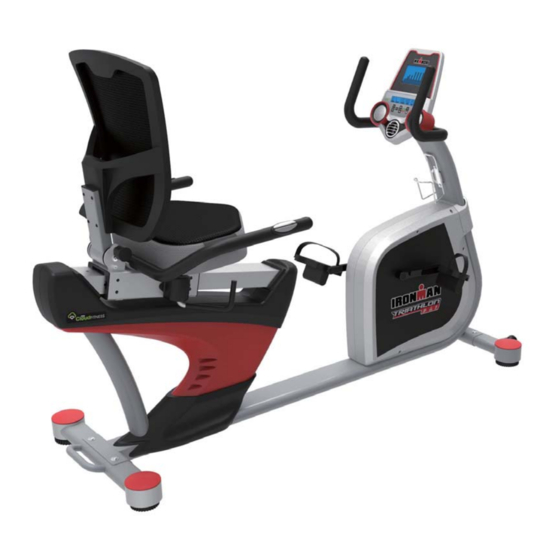
OWNER'S MANUAL
Ironman X- Class 410
Recumbent Bike with Bluetooth
Model 6152
The specifications of this product may vary from this photo and are subject to change without notice.
IRONMAN, IRONMAN TRIATHLON and M-DOT are registered trademarks of World Triathlon Corporation.
This product is licensed by the World Triathlon Corporation.
Advertisement
Table of Contents

Subscribe to Our Youtube Channel
Related Manuals for Ironman Fitness 6152


Summary of Contents for Ironman Fitness 6152
- Page 1 OWNER’S MANUAL Ironman X- Class 410 Recumbent Bike with Bluetooth Model 6152 The specifications of this product may vary from this photo and are subject to change without notice. IRONMAN, IRONMAN TRIATHLON and M-DOT are registered trademarks of World Triathlon Corporation.
- Page 2 6152.01‐041715 ...
-
Page 3: Table Of Contents
TABLE OF CONTENT SERVICE ------------------------------------------------------------------------ 2 LABEL PLACEMENT --------------------------------------------------------- 3 PRODUCT SAFETY ---------------------------------------------------------- 4 OVERVIEW DRAWING ------------------------------------------------------ 5 HARDWARE AND TOOLS LIST ------------------------------------------- 6 PART LIST ---------------------------------------------------------------------- 7 ASSEMBLY ---------------------------------------------------------------------10 SEAT AND BACKREST ADJUSTMENTS-------------------------------19 COMPUTER --------------------------------------------------------------------21 TROUBLESHOOTING & MAINTENANCE ----------------------------- 29 WARM UP ---------------------------------------------------------------------- 30 WARRANTY ------------------------------------------------------------------- 31 FAX FORM --------------------------------------------------------------------- 32... -
Page 4: Service
SERVICE IMPORTANT: FOR NORTH AMERICA ONLY To request product service and order replacement parts, please call our customer service department at: 1-844-641-7922 Monday through Friday, 8:00 AM-5:00 PM Pacific Standard Time, service@paradigmhw.com or email us at: Please visit our website at www.paradigmhw.com. Please have the following information ready when requesting for service: Your name Phone number... -
Page 5: Label Placement
LABEL PLACEMENT CAUTION (Model 6152) ATTENTION (N° 6152) Pedal (0-1) Into the (0-1) (0-2) Into the (0-2) Maximum weight capacity is 350 lbs. AVERTISSEMENT Le poids maximum pout ce produit est 159 kgs. Pour le service a la clientèle For customer assistance call:... -
Page 6: Product Safety
PRODUCT SAFETY Basic precautions should always be followed, including the following safety instructions when using this equipment. Read all instructions before using this equipment. Read all the instructions in this manual and do warm up exercises before using this equipment. Before exercising and to avoid injuring your muscles, perform warm-up exercise for each muscle group is highly recommended. -
Page 7: Overview Drawing
OVERVIEW DRAWING N-10 M-13 M-11 N-11 H-10 G-10 G-11 M-5 M-12 M-3 M-6 M-10 M-2 M-9 H-11 H-12 B-10 G-14 G-13 G-12 J-11 J-5 J-12 J-10 L-10 K-12 L-11 K-11 K-10 K-9 K-8 K-2 D-14 D-15 D-16 D-10 D-12 D-13 D-17 D-11 D-8 D-9... -
Page 8: Hardware And Tools List
HARDWARE & TOOLS LIST M8*15L 4PCS D13.2 4PCS 4PCS M6*15L 1PC D13.2 4PCS 4PCS M8*50L 4PCS M6*10L 2PCS D22 2PCS Step 7B M8*50L 2PCS M6*15L 4PCS Step 7C... -
Page 9: Part List
PART LIST Description Q’ty No. Description Q’ty D-11 Computer set Electric cable Computer D-12 Bolt M5x0.8x12L D-13 Computer Screw M5*0.8*10L Sensor cable Audio cable D-14 Lower computer cable D-15 Handlebar post set Tension cable D-16 Handlebar post Lower hand pulse cable D-17 Fixing plate of computer Upper hand pulse cable... - Page 10 PART LIST Description Q’ty No. Description Q’ty G-12 Bushing J-8 C-clip D22.5xD18.5x1.2T G-13 Adjustable pole J-9 Waved washer D27xD21x0.3T G-14 Cross screw ST4x1.41x12L J-10 Nylon nut M6x1.0x6T H Bracket adjustable tube set J-11 Hex bolt M6x1.0x15L Backrest bracket J-12 Multiple-groove belt H-2 Pin K Fly-wheel set H-3 Swing shaft...
-
Page 11: N-10
PART LIST Description Q’ty No. Description Q’ty M-1 Fixing plate for idle wheel N-8 Curved washer D22xD8.5x1.5T M-2 Bearing N-9 Screw 1/4"x20x40L, M-3 Spring D2.2xD14x55L N-10 screw cover M-4 Nylon nut M8x1.25x8T N-11 Flat washer D14xD6.5x0.8T Allen Wrench with Philips M-5 Plastic washer D50xD10x1.0T N-12 Screwdriver 6mm M-6 Flat washer D30xD8.2x6T... -
Page 12: Assembly
ASSEMBLY Tool: N-13 Open Wrench 13,15mm 1PC 1.Front and Rear Stabilizer Installation 1.1 Front Stabilizer Installation. Lift up the main frame (D-1) from the front, and then align the Front Stabilizer (E-1) onto the front curve of the Main Frame (D-1). Insert 2 Square Neck Screws (N-1) from the bottom, followed by 2 Flat Washers (N-4), 2 Spring Washers (N-3) and 2 Cap Nuts (N-2). - Page 13 ASSEMBLY ASSEMBLY 2.Backrest Adjustable tube fixed Pull out the Backrest Adjustment Knob (H-7), see diagram A, then adjust the Backrest bracket (H-1) into any of the 3 adjustment holes. Then, install the Allen Screw (N-5) into the Backrest bracket (H-1) by using the 5mm Allen Wrench (N-15) provided as shown in diagram B.
- Page 14 ASSEMBLY Tool: N-12 Allen Wrench with Phillips Screwdriver 6mm 1PC 3. Handlebar Post Installation Slide the Upper protective cover (P) onto the Handlebar Post (B-1) see Pic. A. Pull out the Upper pulse cable (B-4) from the Handlebar Post (B-1) as shown in Pic. B. Then connect it with the Lower hand pulse cable (D-16) from the Main Frame (D-1).
- Page 15 ASSEMBLY Tool: N-14 Allen Wrench 4mm 1PC 4. Computer Installation Remove the four Screws (A-2) from the back of the Computer (A-1) Connect the upper pulse cable (B-4) to the console (B-4) pulse cable Connect the computer cable (B-5) to the 9 pin WHITE socket in the back of the computer Install the Computer onto the computer plate (B-2) on the front post and tighten the four Screws (A-2) with the Allen Wrench (N-14).
- Page 16 ASSEMBLY Tool: N-13 Open Wrench 13,15mm 1PC 5. Foot Pedals Installation Put the pedal strap onto the Left and Right pedal first. The Cranks and Foot Pedals are marked “R” for Right and “L” for Left. Insert the pedal shaft of the Left Foot Pedal (O-2) into the threaded hole of the Left Crank (J-1). Turn the pedal shaft by hand in the COUNTER-CLOCKWISE direction until snug.
- Page 17 ASSEMBLY Tool: N-12 Allen Wrench with Phillips Screwdriver 6mm 1PC 6. Bottle Holder Installation Remove the two pre-installed Screws (B-10) from the Handlebar Post (B-1) using the 6mm Allen Wrench with Phillips screwdriver (N-12). Attach the Bottle Holder (Q) onto the handlebar and tighten with the same screws.
- Page 18 ASSEMBLY Tool: N-15 Allen Wrench N-12 Allen Wrench with 5mm 1PC Phillips Screwdriver 6mm 1PC D-17 A-2-1 D-17 D-17 D-17 7A. Seat Handlebar installation Attach the Seat Handlebar (C) with two Allen bolts (N-6) and two Curved Washers (N-8) tighten using the 6mm Allen Wrench (N-12).
- Page 19 ASSEMBLY Tool: N-15 Allen Wrench 5mm 1PC Hardware: N-11 Flat Washer 4PCS N-5 Allen Screw M6*1*15L 7B. Seat Installation 4PCS Attach the Seat (R) to the Seat adjustment bracket (G-1). Ti g h t e n with four Allen Screws (N-5) and four Flat Washers (N-11) using the 5mm Allen Wrench provided (N-15).
- Page 20 ASSEMBLY 8. Adaptor Installation Plug one end of the Adaptor (T) into the power jack (T-1) of the power supply cable on the front of the Left Chain Cover (I-1).Before plugging in, make sure to carefully check the specifications on the Adaptor.
-
Page 21: Seat And Backrest Adjustments
SEAT AND BACKREST ADJUSTMENTS Seat Adjustment Push lever forward to unlock, slide the seat to desired position, and release the lever to lock. To fully tighten and reduce wobbling, pull back on the lever until it’s snug. Backrest Adjustment Pull knob out to unlock, release knob into 1 of the 3 holes on the Backrest bracket (H-1). - Page 22 MOVING THE BIKE Move the bike by using the handlebar located on the Rear Stabilizer (F-1).
-
Page 23: Computer
COMPUTER BUTTON FUNCTION: ON/OFF FAN Turn the fan on or off QUICK START To start or stop workout STOP UP/DOWN To select training mode or adjust function value RESET In stop mode, press the button to return to main menu. Press and hold for 2 seconds to reboot the computer and reset all values to 0. - Page 24 COMPUTER DISPLAY FUNCTION Function Setting Range Unit Display Range TIME 00:00~99:59 ±1;00:00~99:00 Minutes DISTANCE 0.0~99.99 ±1;00:00~99:00 CALORIES 0~9999 ±10;00:00~9990 PULSE 30~230 ±1; 30~230 SPEED 0.0~99.9 0~999 WATT 0~999 ±5; 10~350 OPERATING PROCEDURE 1.POWER ON/OFF – After connecting the power, the console will power on with a long beep sound, LCD display all segments and then enter into User Profile set up mode.
- Page 25 COMPUTER 2. USER PROFILE ˄ ˅ Press UP / DOWN to select User #. ˄ ˅ Press UP / DOWN to turn profile editing on or off. If you choose EDIT ON, you can edit the profile values below. ˄ ˅...
- Page 26 COMPUTER 3.2. Program Mode Press UP or DOWN to select between 12 different workout programs and then press ENTER to set up Target Time. Press START to start workout. ˄ ˅ Resistance levels can be adjusted during exercise by pressing UP or DOWN Press STOP to pause the workout reading, and you can press START to continue the workout.
- Page 27 COMPUTER 3.3 User Program User Program allows you to create your own workouts based on resistance level and time intervals. ˄ ˅ Press UP and DOWN to create the profile, press ENTER to input additional resistance level, then press and hold ENTER for 2 seconds to exit profile stetting. Press START to start work out.
- Page 28 COMPUTER ...
- Page 29 COMPUTER 3.5 WATT ˄ ˅ Press UP and DOWN to setting WATT and Time target. Press START to start work out. Press STOP to pause the workout reading, and you can press START to continue the workout. Press RESET to return to main page. 4.
- Page 30 COMPUTER 5. Bluetooth Mode Enable Bluetooth on your smart device. Search for and connect to console (name is on the back of the console). When your smart device is connected to the console, the Bluetooth symbol will appear on the LCD. Please note: 1.
-
Page 31: Troubleshooting & Maintenance
TROUBLESHOOTING & MAINTENANCE TROUBLESHOOTING Computer not working correctly Check to make sure the computer cable is connected securely. Check that the AC Adaptor is securely connected to the Power Supply Cable and to the electrical wall outlet. The bike trainer wobbles or shakes when in use Turn the adjustable leveler on the front stabilizer or U shape rail as needed to level the bike trainer. - Page 32 WARRANTY MANUFACTURER’S LIMITED WARRANTY Paradigm Health & Wellness warrants to the original purchaser that this product is free from defects in material and workmanship when used for the purpose intended, under the conditions that it has been installed and operated in accordance with Paradigm’s Owner’s Manual. Paradigm’s obligation under this warranty applies to the following: COMPONENT LENGTH OF WARRANTY...
-
Page 33: Warm Up
WARM UP Quadriceps Stretch With one hand against a wall for balance, reach behind you and pull your right foot up. Bring your heel as close to your buttocks as possible. Hold for 15 counts and repeat with left foot up. Inner Thigh Stretch Sit with the soles of your feet together with your knees pointing outward. -
Page 34: Fax Form
FAX FORM Paradigm Health & Wellness, Inc. PARTS REQUEST FAX FORM Please fax this form to (1-626-810-2166) OR YOU CAN EMAIL CUSTOMER SERVICE REQUESTS TO service@paradigmhw.com NAME: _______________________________________________________ ADDRESS: ____________________________________________________ CITY ______________ STATE ______________ ZIP ___________________ TELEPHONE: (Day) _____________________________________________ (Night) ____________________________________________ (Email Address) ____________________________________ SERIAL#: __________________________________________ MODEL#: __________________________________________...
Need help?
Do you have a question about the 6152 and is the answer not in the manual?
Questions and answers