Table of Contents
Advertisement
Quick Links
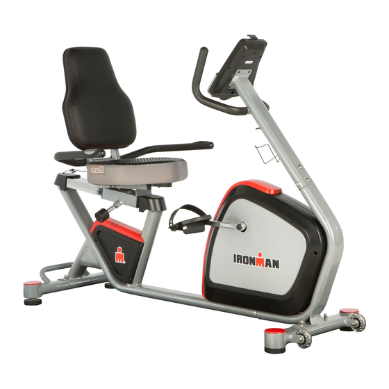
OWNER'S MANUAL
IRONMAN Recumbent Bike
with Bluetooth
Model 6155
The specifications of this product may vary from this photo and are subject to change without notice.
IRONMAN, IRONMAN TRIATHLON and M-DOT are registered trademarks of World Triathlon Corporation.
This product is licensed by the World Triathlon Corporation.
Advertisement
Table of Contents

Related Manuals for Ironman Fitness 6155


Summary of Contents for Ironman Fitness 6155
- Page 1 OWNER’S MANUAL IRONMAN Recumbent Bike with Bluetooth Model 6155 The specifications of this product may vary from this photo and are subject to change without notice. IRONMAN, IRONMAN TRIATHLON and M-DOT are registered trademarks of World Triathlon Corporation. This product is licensed by the World Triathlon Corporation.
- Page 2 6155.01‐100815...
-
Page 3: Table Of Contents
TABLE OF CONTENT SERVICE ------------------------------------------------------------------------ 2 LABEL PLACEMENT --------------------------------------------------------- 3 PRODUCT SAFETY ---------------------------------------------------------- 4 OVERVIEW DRAWING ------------------------------------------------------ 5 HARDWARE AND TOOLS LIST ------------------------------------------- 6 PART LIST ---------------------------------------------------------------------- 7 ASSEMBLY --------------------------------------------------------------------- 10 COMPUTER -------------------------------------------------------------------- 19 TROUBLESHOOTING & MAINTENANCE ----------------------------- 23 WARM UP ----------------------------------------------------------------------- 24 WARRANTY -------------------------------------------------------------------- 25 FAX FORM ---------------------------------------------------------------------- 26... -
Page 4: Service
SERVICE IMPORTANT: FOR NORTH AMERICA ONLY For best product service, please e-mail: Servic@paradigmhw.com Response Time: 1-2 Business Days. Or call 1-844-641-7922 Daily, 8:00 AM – 5:00PM Pacific Standard Time. Please have the following information ready when requesting service: Your name Phone number Model number Serial number... -
Page 5: Label Placement
LABEL PLACEMENT ... -
Page 6: Product Safety
PRODUCT SAFETY Basic precautions should always be followed, including the following safety instructions when using this equipment. Read all instructions before using this equipment. Read all the instructions in this manual and do warm up exercises before using this equipment. Before exercising and to avoid injuring your muscles, perform warm-up exercise for each muscle group is highly recommended. -
Page 7: Overview Drawing
OVERVIEW DRAWING ... -
Page 8: Hardware And Tools List
HARDWARE & TOOLS LIST ... -
Page 9: Part List
PART LIST Description Q’ty No. Description Q’ty Computer set D-14 Allen Bolt M8x1.25x55L A-1 Computer D-15 Square Neck Bolt M8x1.25x55L A-2 Screw M5x10L D-16 Sliding Tube Handlebar Post Set D-17 Flat Washer D16xD8.5x1.2T B-1 Handlebar Post D-18 Spring Washer D15.4xD8.2x2T B-2 Screw M5x0.8x15L D-19 Domed Nut M8x1.25x15L B-3 Cap Front Stabilizer Set... - Page 10 PART LIST Description Q’ty No. Description Q’ty I-6 Screw ST4.2x1.4x20L L-1 Fixed Plate for Magnet Flywheel Set L-2 Spring D1.0x55L J-1 Flywheel L-3 Nylon Nut M6x1.0x6T J-2 Flywheel Axle L-4 Flat Washer D13xD6.5x1.0T J-3 Bearing L-5 Nylon Washer D13xD19x1.5T J-4 Unilateral BearingD35x16 L-6 Nut M6x1x6T J-5 Bearing L-7 Hex Bolt M6x65L...
- Page 11 PART LIST Description Q’ty No. Description Q’ty N-7 Allen Bolt M8x1.25x40L O-1 Left Pedal N-8 Allen Bolt M6x1.0x35L O-2 Right Pedal N-9 Flat Washer D14xD6.5x0.8T Adaptor N-10 Allen Wrench 6mm w/Screwdriver P-1 Power Jack N-11 Open Wrench 13,15mm Bottle Holder N-12 Allen Wrench 5mm Seat N-13 Round Knob Backrest...
-
Page 12: Assembly
ASSEMBLY Tool: N-11 Open Wrench 13,15mm 1PC 1.Front and Rear Stabilizer Installation 1.1 Front Stabilizer Installation. Lift up the Main Frame (D-1) from the front, and then align the Front Stabilizer (E-1) onto the front curve of the Main Frame (D-1). Insert 2 Carriage Bolts (N-1) from the bottom, followed by 2 Flat Washers (N-4), 2 Spring Washers (N-3) and 2 Cap Nuts (N-2). - Page 13 ASSEMBLY Tool: N-10 Allen Wrench with Phillips Screwdriver 6mm 1PC FRONT SIDE 2A. Handlebar Post Installation Pull out the Upper Hand Pulse Cable (B-5) from the Handlebar Post (B-1), then connect it with the Lower Handle Pulse Cable (D-2) from the Main Frame (D-1). Connect the Upper Computer Cable (B-6) from the Handlebar Post (B-1) to the Lower Computer Cable (D-9) from the Main Frame (D-1) as shown in Pic.
- Page 14 ASSEMBLY 2B.Bottle Holder Installation Remove the two pre-installed Screws (B-2) from the Handlebar Post (B-1) by using the Allen Wrench (N-10). Attach the Bottle Holder (Q) onto the handlebar and tighten with the same screws. Hardware: N-5 Allen Bolt N-3 Spring Washer N-6 Curved Washer N-4 Flat Washer...
- Page 15 ASSEMBLY Tool: N-10 Allen Wrench with Phillips Screwdriver 6mm 1PC 3. Computer Installation Remove the four Screws (A-2) from the back of the Computer (A-1) Connect Upper Hand Pulse Cable (B-5) to the Console Pulse Cable. Connect the Upper Computer Cable (B-6) to Console Computer Cable. Attach the Computer (A-1) onto the mounting plate of the Handlebar Post (B-1) and tighten with the four previously removed Screws (A-2).
- Page 16 ASSEMBLY Tool: N-12 Allen Wrench 5mm 1PC Hardware: N-8 Allen Bolt M6x1.0x35L 4PCS N-9 Flat washer D14xD6.5x0.8T 4PCS 4A. Seat Installation Align the holes of the Seat (R) to the Seat Post (G-1). Secure the seat with four Allen Bolts (N-8) and four Flat Washers (N-9) by using the Allen Wrench (N-12) provided.
- Page 17 ASSEMBLY Tool: N-10 Allen Wrench with Phillips Screwdriver 6mm 1PC 5. Seat Handlebar installation Attach the Seat Handlebar (C-1) to the Seat Post (G-1) with four Allen Bolts (N-5), four Spring Washers (N-3) and four Flat Washers (N-4) then tighten with the Allen Wrench (N-10) provided as shown in Pic.
- Page 18 ASSEMBLY 6. Seat Adjustment Adjust the seat to the desired position and insert the Round Knob (N-13) into the hole on the side of Seat Post (G-1) turn the Round Knob into Clockwise until secured.
- Page 19 ASSEMBLY Tool: N-11 Open Wrench 13,15mm 1PC Pedal Installation Put the pedal strap onto the Left and Right pedal first. The Cranks and Pedals are marked “R” for Right and “L” for Left. Insert the Left Pedal (O-1) into the Left Crank (K-8). Turn the pedal shaft by hand in the COUNTER-CLOCKWISE direction until snug.
- Page 20 ASSEMBLY 8. Adaptor Installation Plug one end of the Adaptor (P) into the Power Jack (P-1) located on the front of the Left Chain Cover (I-1). Plug the other end of the Adaptor (P) to the electrical wall outlet.
-
Page 21: Computer
COMPUTER DISPLAY FUNCTIONS : ITEM DESCRIPTION TIME Workout time displayed during exercise. Range 0:00 ~ 99:59 SPEED Workout speed displayed during exercise. Range 0.0 ~ 99.9 DISTANCE Workout distance displayed during exercise. Range 0.0 ~ 99.9 CALORIES Burned calories during workout display. - Page 22 COMPUTER KEY FUNCTION: ITEM DESCRIPTION ‧ Increase resistance level ‧ Setting selection. ‧ Decrease resistance level Down ‧ Setting selection. ‧ Confirm setting or selection. Enter ‧ Hold on pressing for 2 seconds, computer will reboot and start from user setting. Reset ‧...
- Page 23 COMPUTER Manual Mode Press START in main menu may start workout in manual mode. Press UP or DOWN to select workout program, choose Manual and press ENTER. Press UP or DOWN to preset TIME, DISTANCE, CALORIES, PULSE and press ENTER to confirm.
- Page 24 COMPUTER Sporty Mode 1. Press UP or DOWN to select workout program, choose Sporty mode and press ENTER. 2. Press UP or DOWN to preset TIME. 3. Press START/STOP key to start workout. Press UP or DOWN to adjust load level. 4.
-
Page 25: Troubleshooting & Maintenance
TROUBLESHOOTING & MAINTENANCE TROUBLESHOOTING Computer not working correctly Check to make sure the computer cable is connected securely. Check that the AC Adaptor is securely connected to the Power Supply Cable and to the electrical wall outlet. The bike trainer wobbles or shakes when in use Turn the adjustable leveler on the front stabilizer or U shape rail as needed to level the bike trainer. -
Page 26: Warm Up
WARM UP Quadriceps Stretch With one hand against a wall for balance, reach behind you and pull your right foot up. Bring your heel as close to your buttocks as possible. Hold for 15 counts and repeat with left foot up. Inner Thigh Stretch Sit with the soles of your feet together with your knees pointing outward. -
Page 27: Warranty
WARRANTY MANUFACTURER’S LIMITED WARRANTY Paradigm Health & Wellness warrants to the original purchaser that this product is free from defects in material and workmanship when used for the purpose intended, under the conditions that it has been installed and operated in accordance with Paradigm’s Owner’s Manual. Paradigm’s obligation under this warranty applies to the following: COMPONENT LENGTH OF WARRANTY... -
Page 28: Fax Form
FAX FORM Paradigm Health & Wellness, Inc. PARTS REQUEST FAX FORM Please fax this form to (1-626-810-2166) OR YOU CAN EMAIL CUSTOMER SERVICE REQUESTS TO service@paradigmhw.com NAME: _______________________________________________________ ADDRESS: ____________________________________________________ CITY ______________ STATE ______________ ZIP ___________________ TELEPHONE: (Day) _____________________________________________ (Night) ____________________________________________ (Email Address) ____________________________________ SERIAL#: __________________________________________ MODEL#: __________________________________________...
Need help?
Do you have a question about the 6155 and is the answer not in the manual?
Questions and answers