Motorola AP7131 Installation Manual
Hide thumbs
Also See for AP7131:
- Product reference manual (694 pages) ,
- Installation manual (58 pages) ,
- Brochure (12 pages)
Table of Contents
Advertisement
Quick Links
Advertisement
Table of Contents

Related Manuals for Motorola AP7131


Summary of Contents for Motorola AP7131
- Page 1 AP7131 Access Point INSTALLATION GUIDE...
- Page 2 AP-7131 Access Point MOTOROLA SOLUTIONS and the Stylized M Logo are registered in the US Patent & Trademark Office. © Motorola Solutions, Inc. 2013. All rights reserved.
-
Page 3: Table Of Contents
4.1 AP7131 Physical Characteristics ........ - Page 4 7.0 AP7131 Series RoHS Compliance ........
-
Page 5: Introduction
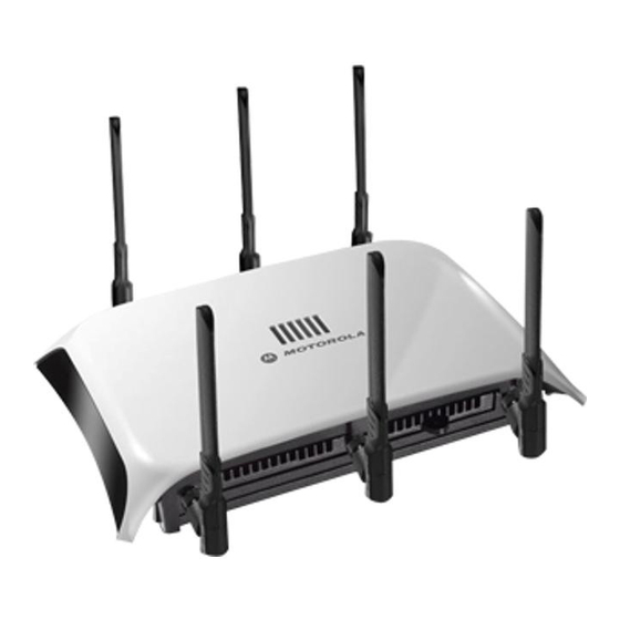
Installation Guide 1 Introduction As a standalone Access Point, an AP7131 series Access Point provides small and medium-sized businesses with a consolidated wired and wireless networking infrastructure, all in a single device. The integrated router, gateway, firewall, DHCP and Power-over-Ethernet (PoE) simplify and reduce the costs associated with networking by eliminating the need to purchase and manage multiple pieces of equipment. -
Page 6: Warnings
AP-7131 Access Point 1.2 Warnings • Read all installation instructions and site survey reports, and verify correct equipment installation before connecting the Access Point. • Remove jewelry and watches before installing this equipment. • Verify the unit is grounded before connecting it to the power source. •... -
Page 7: Hardware Installation
Installation Guide Hardware Installation An AP7131 or AP7131N Access Point installation includes mounting the Access Point, connecting the Access Point to the network, connecting antennae and applying power. Installation procedures vary for different environments. Both an AP7131 and AP7131N model Access Point have the following port designations: •... -
Page 8: Access Point Placement
• Point the Access Point antennas downward if attaching to the ceiling (external antenna models only). To maximize the Access Point’s radio coverage area, Motorola Solutions recommends conducting a site survey to define and document radio interference obstacles before installing the Access Point. -
Page 9: Antenna Options
Installation Guide 2.3.1 Antenna Options Motorola Solutions supports two antenna suites for AP7131 and AP7131N models. One antenna suite supporting the 2.4 GHz band and another antenna suite supporting the 5 GHz band. Select an antenna model best suited to the intended operational environment of your Access Point. - Page 10 Antenna Module ML-2452-PTA3M3-036 3 Port MIMO Antenna An additional adapter is required to use ML-2499-11PNA2-01R and NOTE ML-2499-BYGA2-01R model antennas. Please contact Motorola Solutions for more information. The 5 GHz antenna suite includes the following models: Part Number Antenna Type...
-
Page 11: Power Injector System
Injector is separately ordered and not shipped with an existing AP SKU. An AP7131 and AP7131N can also be used with the 3af power injector (AP-PSBIAS-1P2-AFR). However, AP functionality is limited when powered by an AP-PSBIAS-1P2-AFR, since the AP has Ethernet connectivity limited to only the GE1 port. - Page 12 AP-7131 Access Point A separate Power Injector is required for each Access Point comprising the network. The following guidelines should be adhered to before cabling the Power Injector to an Ethernet source and an Access Point: • Do not block or cover airflow to the Power Injector. •...
-
Page 13: Mounting The Access Point
2.4 Mounting the Access Point Both the AP7131 and AP7131N can attach to a wall, mount under a suspended T-Bar or above a ceiling (plenum or attic) following the same installation instructions. Choose one of the following mounting options based on the physical environment of the coverage area. - Page 14 AP-7131 Access Point...
- Page 15 Installation Guide To mount the Access Point on a wall using the provided template: 1. Copy the template (on the previous page) to a blank piece of paper. Do not reduce or enlarge the scale of the template. If printing the mounting template (on the previous page) from an NOTE electronic PDF, dimensionally confirm the template by measuring each value for accuracy.
- Page 16 AP-7131 Access Point For Motorola Power Injector installations: a. Connect an RJ-45 CAT5 Ethernet cable between the network data supply (host) and the Power Injector’s Data In connector. b. Connect an RJ-45 CAT5 Ethernet cable between the Power Injector’s Data & Power Out connector and the Access Point’s GE1/POE ports.
-
Page 17: Suspended Ceiling T-Bar Installation
To install the Access Point on a ceiling T-bar: 1. Motorola Solutions recommends you loop a safety wire — with a diameter of at least 1.01 mm (.04 in.), but no more than 0.158 mm (.0625 in.) — through the tie post (above the Access Point’s console connector) and secure the loop. - Page 18 AP-7131 Access Point e. Attach the power supply line cord to a power supply. Do not actually connect to the power source until the cabling portion CAUTION of the installation is complete LED Indicators 5. Verify the behavior of the Access Point LEDs. For more information, see 6.
-
Page 19: Above The Ceiling (Plenum) Installation
.625 to .75 inches thick. Both the AP7131 and AP7131N are Plenum rated to UL2043 and NEC1999 NOTE to support above the ceiling installations. To ensure UL compliance and... - Page 20 Antenna Options For information on the antennas available to the Access Point, see 12. Motorola Solutions recommends attaching safety wire to the Access Point safety wire tie point or security cable (if used) to the Access Point’s lock port. 13. Align the ceiling tile into its former ceiling space.
- Page 21 Installation Guide For Motorola Power Injector installations: a. Connect an RJ-45 CAT5 Ethernet cable between the network data supply (host) and the Power Injector’s Data In connector. b. Connect an RJ-45 CAT5 Ethernet cable between the Power Injector’s Data & Power Out connector and the Access Point’s GE1/POE port.
-
Page 22: Led Indicators
Both AP7131 and AP7131N model Access Point have six LEDs on the top of the Access Point housing, and one optional LED light pipe at the bottom of the unit. However, an AP7131 model Access Point does not use LED 6, as no third radio is available. -
Page 23: Three Radio Ap7131 Leds
The LEDs on the top housing of the Access Point are clearly visible in wall and below ceiling installations. The top housing LEDs have the following display and functionality: 2.5.1 Three Radio AP7131 LEDs A three radio model AP7131N Access Point has the following unique LED behavior:... -
Page 24: Single Radio 2.4 Ghz Leds
AP-7131 Access Point 2.5.3 Single Radio 2.4 GHz LEDs A single 2.4 GHz radio model Access Point has the following unique LED behavior: LED 1 LED 2 (LAN) LED 3 (WAN) LED 4 - 5 GHz LED 5 - 2.4 GHz LED 6 Blinking Red Blinking Green... -
Page 25: Rear Ap7131 Led
Installation Guide 2.5.5 Rear AP7131 LED The LED on the rear (bottom) of the Access Point is optionally viewed using a single (customer installed) extended light pipe, adjusted as required to suit above the ceiling installations. The LED light pipe has the following color... -
Page 26: Basic Access Point Configuration
AP-7131 Access Point Basic Access Point Configuration Once the Access Point is installed and powered on, complete the following steps to get the device up and running and access management functions: 1. Attach an Ethernet cable from the Access Point to a controller with an 802.3af compatible power source or use the PWRS-14000-148R power supply to supply power to the Access Point (once fully cabled). - Page 27 Installation Guide 3. Enter the default username admin in the Username field. 4. Enter the default password motorola in the Password field. 5. Click the Login button to load the management interface. When logging in for the first time, you’re prompted to change the NOTE password to enhance device security in subsequent logins.
- Page 28 AP-7131 Access Point The Introduction screen displays the various actions that can be performed using the wizard under the Function Highlight field. Use the Choose One type to Setup the Access Point field options to select the type of wizard to run. The Typical Setup is the recommended wizard.
- Page 29 Installation Guide For the purposes of this guide, use the Typical Setup (Recommended) option to simplify the process of getting the Access Point up and running quickly with a minimum number of changes to the Access Point’s default configuration. For information on using the Access Point’s Advanced Setup option, refer to the WiNG Access Point System Reference Guide to familiarize yourself with the feature set supported by the WiNG operating system.
- Page 30 UI to connect to the Access Point, provision its configuration and administrate the Access Point’s configuration. If designating the Access Point as a Standalone AP, Motorola Solutions NOTE recommends the Access Point’s UI be used exclusively to define its device configuration, and not the CLI.
- Page 31 Installation Guide 12. The Typical Setup Wizard displays the Network Topology screen to define how the Access Point handles network traffic. 13. Select an Access Point Mode from the available options. • Router Mode -In Router Mode, the Access Point routes traffic between the local network (LAN) and the Internet or external network (WAN).
- Page 32 AP-7131 Access Point 14. Select Next. The Typical Setup Wizard displays the LAN Configuration screen to set the Access Point's LAN interface configuration. 15. Set the following DHCP and Static IP Address/Subnet information for the LAN interface: • Use DHCP - Select the checkbox to enable an automatic network address configuration using the Access Point’s DHCP server.
- Page 33 Installation Guide • DNS Forwarding - Select this option to allow a DNS server to translate domain names into IP addresses. If this option is not selected, a primary and secondary DNS resource must be specified. DNS forwarding is useful when a request for a domain name is made but the DNS server, responsible for converting the name into its corresponding IP address, cannot locate the matching IP address.
- Page 34 AP-7131 Access Point 18. Select Next. The Typical Setup Wizard displays the RADIUS Server Configuration screen if required. Otherwise, the Typical Setup Wizard displays the Summary and Commit screen. 19. Use the Radius Server Configuration screen to configure the users for the onboard RADIUS server. Use the screen to add, modify and remove RADIUS users.
- Page 35 Installation Guide 20. Select Add User to display the dialog to enter user information to add to the RADIUS server user database. 21. Enter the following user information: • Username - Provide a user name used to authenticate the user. •...
- Page 36 AP-7131 Access Point 27. Select Next. The Typical Setup Wizard displays the Summary and Commit screen to summarize the screens (pages) and settings updated using the Typical Setup Wizard. No user intervention or additional settings are required. Its an additional means of validating the Access Point’s updated configuration before it’s deployed.
-
Page 37: Specifications
Installation Guide Specifications 4.1 AP7131 Physical Characteristics An AP7131 model Access Point has the following physical characteristics: Dimensions 5.50 in. Depth x 7.88 in. Width x 1.10 in. Height 14 cm Depth x 20.32 cm Width x 2.79 cm Height... -
Page 38: Electrical Characteristics
AP-7131 Access Point 4.3 Electrical Characteristics The AP7131 and AP7131N model Access Points have the following electrical characteristics: Operating Voltage 48VDC (compatible with POE .3af/.3at Draft) Operating Current Not to exceed 750mA @ 48VDC Power 48VDC, 0.75A 4.4 AP7131 Radio Characteristics... -
Page 39: Ap7131N Radio Characteristics
Installation Guide 4.5 AP7131N Radio Characteristics An AP7131N model Access Point has the following radio characteristics: Operating Channels All channels from 4920 MHz to 5825 MHz except channel 52 -64 Channels 1-13 (EU), Channels 1-11 (US/Canada) Channel 14 (2484 MHz) Japan only Actual operating frequencies depend on regulatory Data Rates Supported 802.11g: 1,2,5.5,11,6,9,12,18,24,36,48, and 54Mbps 802.11a: 6,9,12,18,24,36,48, and 54Mbps... -
Page 40: Regulatory Information
These devices (AP-7131 and AP-7131N) are approved under Motorola Solutions, Inc. All Motorola Solutions devices are designed to be compliant with rules and regulations in locations they are sold and will be labeled as required. Any changes or modifications to Motorola Solutions equipment, not expressly approved by Motorola Solutions, could void the user's authority to operate the equipment. -
Page 41: Wireless Device Country Approvals
Installation Guide 5.3 Health and Safety Recommendations 5.3.1 Warnings for the use of Wireless Devices Please observe all warning notices with regard to the usage of wireless devices. 5.3.2 Potentially Hazardous Atmospheres – Fixed Installations You are reminded of the need to observe restrictions on the use of radio devices in fuel depots, chemical plants etc. and areas where the air contains chemicals or particles (such as grain, dust, or metal powders). -
Page 42: Power Supply
AP-7131 Access Point 5.5 Power Supply Use only a Motorola Solutions approved power supply output rated at 48Vdc and minimum 0.75A. The power supply shall be Listed to UL/CSA 60950-1; and certified to IEC60950-1 and EN60950-1 with SELV outputs. Use only a Motorola approved power supply. Use of alternative power supply will invalidate any approval given to this device and may be dangerous. -
Page 43: Radio Frequency Interference Requirements - Canada
Installation Guide Radio Transmitters (Part 15) This device complies with Part 15 of the FCC Rules. Operation is subject to the following two conditions: (1) this device may not cause harmful interference, and (2) this device must accept any interference received, including interference that may cause undesired operation. -
Page 44: Ce Marking And European Economic Area (Eea)
• Italy requires a user license for outside usage. 5.9.1 Statement of Compliance Motorola Solutions hereby, declares that this device is in compliance with the essential requirements and other relevant provisions of Directive 1999/5/EC. A Declaration of Conformity may be obtained from http://www.motorolasolutions.com/doc. -
Page 45: Other Countries
Installation Guide 5.9.4 Other Countries Australia Use of 5GHz RLAN’s in Australia is restricted in the following band 5.50 – 5.65GHz. Brazil Regulatory declarations for AP7131N - BRAZIL Note: The certification mark applied to the AP7131N is for Restrict Radiation Equipment. This equipment operates on a secondary basis and does not have the right for protection against harmful interference from other users including same equipment types. - Page 46 AP-7131 Access Point radio-frequency devices must be susceptible with the interference from legal communications or ISM radio wave radiated devices. Wireless device operate in the frequency band of 5.25-5.35 GHz, limited for Indoor use only. 在 5.25-5.35 秭赫頻帶內操作之無線資訊傳輸設備,限於室內使用 Korea For a radio equipment using 2400~2483.5MHz or 5725~5825MHz, the following two expressions should be displayed 1.
-
Page 47: Waste Electrical And Electronic Equipment (Weee)
Installation Guide 5.10 Waste Electrical and Electronic Equipment (WEEE) English: For EU Customers: All products at the end of their life must be returned to Motorola Solutions for recycling. For information on how to return product, please go to: http://www.motorolasolutions.com/recycling/weee. -
Page 48: Turkish Weee Statement Of Compliance
AP-7131 Access Point Dansk: Til kunder i EU: Alle produkter skal returneres til Motorola Solutions til recirkulering, når de er udtjent. Læs oplysningerne om returnering af produkter på: http://www.motorolasolutions.com/recycling/weee. Ελληνικά: Για πελάτες στην Ε.Ε.: Όλα τα προϊόντα, στο τέλος της διάρκειας ζωής τους, πρέπει να επιστρέφονται... -
Page 49: Motorola Solutions Support Center
• Model number or product name • Software type and version number Motorola Solutions responds to calls by e-mail, telephone, or fax within the time limits set forth in support agreements. If you purchased your product from a Motorola Solutions business partner, contact that business partner for support. -
Page 50: Ap7131 Series Rohs Compliance
塑料和聚合物部件 (Plastic and Polymeric Parts) 光学和光学组件 (Optics and Optical Components) 电池 (Batteries) O:表示该有毒有害物质在该部件所有均质材料中的含量均在 SJ/T11363-2006 标准规定的限量要求以下。 X: 表示该有毒有害物质至少在该部件的某一均质材料中的含量超出 SJ/T11363-2006 标准规定的限量要求。 对销售之日的所售产品,本表表示,公司供应链的电子信息产品可能包含这些物质。注意:在所售产品中可能会也 可能不会含有所有所列的部件。 This table was created to comply with China RoHS requirements for Motorola Solution’s AP7131 and AP7131N model Access Points. - Page 51 Installation Guide...
- Page 52 Schaumburg, IL 60196-1078, U.S.A. http://www.motorolasolutions.com MOTOROLA, MOTO, MOTOROLA SOLUTIONS and the Stylized M Logo are trademarks or registered trademarks of Motorola Trademark Holdings, LLC and are used under license. All other trademarks are the property of their respective owners. © 2013 Motorola Solutions, Inc. All Rights Reserved.
Need help?
Do you have a question about the AP7131 and is the answer not in the manual?
Questions and answers