Motorola AP 7161 Installation Manual
802.11n 3x3 multiple input
multiple output (mimo) access point
Hide thumbs
Also See for AP 7161:
- Installation manual (64 pages) ,
- Reference manual (954 pages) ,
- Installation manual (48 pages)
Table of Contents
Advertisement
Advertisement
Table of Contents

Related Manuals for Motorola AP 7161


Summary of Contents for Motorola AP 7161
- Page 1 AP 7161 ACCESS POINT INSTALLATION GUIDE...
- Page 2 AP 7161 Access Point MOTOROLA SOLUTIONS and the Stylized M Logo are registered in the US Patent & Trademark Office. © Motorola Solutions, Inc. 2014. All rights reserved.
-
Page 3: Table Of Contents
1.3.1 AP 7161 4.9 and 5 GHz Antennas ....... . - Page 4 AP 7161 Access Point 2.3 AP 7161 VMM Mounting and Installation ......41 2.4 AP 7161 Power Options Using Power over Ethernet .
- Page 5 8.0 AP 7161 Series ROHS Compliance ........
-
Page 6: Introduction
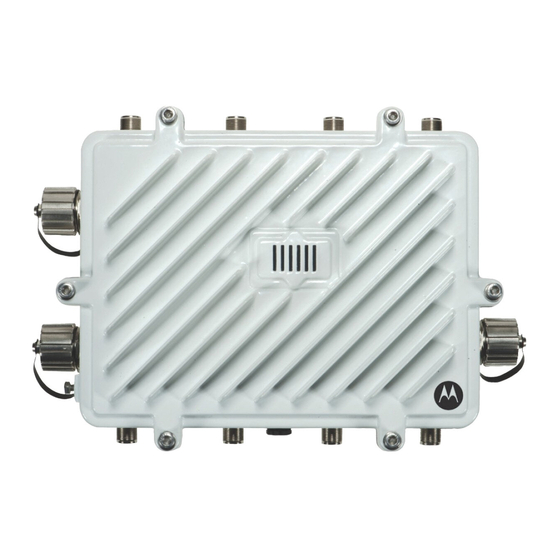
AP 7161 Access Point 1 Introduction Perfect for extending network coverage to outside areas, the AP 7161 brings the latest 802.11n 3x3 Multiple Input Multiple Output (MIMO) tri-radio design together with rugged outdoor performance. True perimeter security is provided using either a dedicated dual band sensor or software mode for both 2.4GHz and 5GHz bands to deliver 24x7 rogue detection and termination. -
Page 7: Document Conventions
AP 7161 offers band unlocked radio flexibility. The user can choose between 2.4Ghz, 5Ghz and 4.9Ghz bands for the radio type. The AP 7161 supports 3x3 MIMO technology, reaching a maximum data rate of 300 Mbps to maintain high performance and better quality of transmission. -
Page 8: Ap 7161 Hardware
AP-7161-66S40-JP AP 7161 OUTDOOR DUAL RADIO 802.11N AP W/SENSOR JP The AP 7161 Vehicle Mounted Modem (VMM) is a software profile within the WiNG 5 architecture that uses the same hardware as the AP 7161 Access Point infrastructure models. 1.3 AP7161 Antenna Accessories Antennas must be ordered separately. -
Page 9: Ap 7161 4.9 And 5 Ghz Antennas
Gain: 3.6dBi (typical) to 4.5dBi (maximum) @2.4GHz, 4.5 (typical) to 5.4 (maximum) @5.8GHz Connector: RP-SMA male The ML-2452-HPAG5A8-01 multi band antenna is suggested for use with AP 7161 NOTE sensor models AP-7161-66S40-US and AP-7161-66S40-WR on ports R3-A and R3-B, respectively. The is suggested for use with AP 7161 VMM. -
Page 10: Ap 7161 11J Antennas
AP 7161 Access Point 1.3.3 AP-7161-66S40-JP Antennas Height Part Number Band Gain Description (inches) ML-2452-HPAG5A8-01 2.4-5.8 4.5/7.5 Outdoor rated Type: dipole Gain: 4.5dBi@2.4GHz, 7.5dBi@5GHz, 5.5dBi@4.9GHz Connector: N-male ML-2452-VMM3M3-036 2.4-5.8 3.6/4.0 Outdoor rated Vehicle Mounted MIMO Omni Patch Type: VMM Gain: 3.6dBi (typical) to 4.5dBi (maximum) @2.4GHz, 4.5 (typical) to 5.4 (maximum) @5.8GHz... -
Page 11: Outdoor Poe Hardware And Mounting Accessories
1.4 Outdoor PoE Hardware and Mounting Accessories The AP 7161 is a Power over Ethernet (PoE) device. When deployed, the use of an outdoor rated PoE power supply and mounting bracket may be required. The recommended Motorola Solutions PoE accessories are listed in the AP 7161 Power Options Using Power over Ethernet on page 45 following table. -
Page 12: Package Contents
• AP 7161 Access Point • Weatherproof RJ45 plug kit • AP 7161 Access Point Installation Guide (this document) The following items are not included with the AP 7161 Access Point models but can be ordered from Motorola Solutions: • Antennas •... -
Page 13: Hardware Installation Guidelines
7161 Access Point. 1.8.1 Precautions Before installing an AP 7161 model Access Point, verify the following grounding and lightning protection notes: • The installation professional should be familiar with all grounding requirements and regional codes and ensure that the Access Point and mounting asset are properly grounded. The grounding cable for an AP 7161 must be at a minimum a #10 gauge wire cross section. -
Page 14: Warnings
AP 7161 Access Point 1.8.2 Warnings • Read all installation instructions and site survey reports, and verify correct equipment installation before connecting the Access Point to its power source. • Remove jewelry and watches before installing this equipment. • Verify that the unit is grounded before connecting it to the power source. -
Page 15: Access Point Placement
An AP 7161 must be installed by trained professionals familiar with RF planning and regulatory limits defined by the regulatory bodies of the country where the devices are being deployed. All common precautions for grounding and Electrostatic Discharge (ESD) protection should be observed during deployment and installation. -
Page 16: Ap 7161 Antenna Connectors
AP 7161 Access Point 1.10.2 AP 7161 Antenna Connectors AP 7161 two radio models (AP-7161-66040-US and AP-7161-66040-WR) are configured with six N type connectors to support two active WLAN data radios. When mounting antennas to ports R1-A, R1-B, and R1-C, ensure that you have selected the appropriate band for the configured radio that uses ports R1-A, R1-B, and R1-C. -
Page 17: Ap 7161 Console, Ge1/Poe And Ge2 Ports
All antenna connectors should be covered with weatherproofing tape. WARNING! 1.10.3 AP 7161 Console, GE1/POE and GE2 Ports The AP 7161 has Ethernet ports for external console, GE1/POE, and GE2 connections.To gain access to the ports you will need to remove the protective caps. - Page 18 When making connections using these ports, a properly rated RJ45 connector is required. One weatherproof RJ45 plug kit is provided with each Access Point. When connecting cables to the AP 7161 Ethernet ports, follow the instructions in the connector packaging and tighten the connectors to create a weatherproof seal. Shielded cables...
-
Page 19: Ap 7161 Grounding Screw
1.10.4 AP 7161 Grounding Screw The grounding screw is located to the right of the GE1/POE port and above the GND symbol. The grounding cable for an AP 7161 must be at a minimum a #10 gauge wire cross WARNING! section. -
Page 20: Led Indicators
The AP 7161 Access Point has six LEDs on the top of the Access Point housing. When the Access Point is positioned with the Motorola Solutions logo in the lower right corner, LED 1 is on the left and LED 6 is on the right. -
Page 21: Two Radio Leds
White at 1 second interval indicates “no adoption”. Solid White indicates normal operation. If LED 6 remains blinking Red for longer than 10 minutes, cycle the power to the WARNING! unit. If the condition persists, contact the Motorola Solutions support center. -
Page 22: Three Radio Leds
AP 7161 Access Point 1.11.2 Three Radio LEDs A three radio model Access Point with sensor (P/N AP-7161-66S40-US and AP-7161-66S40-WR) has the following unique LED behavior: LED 1 LED 2 LED 3 LED 4 LED 5 LED 6 (Sensor) (2.4 GHz) -
Page 23: Ap 7161 Hardware Mounting And Installation
2 AP 7161 Hardware Mounting and Installation It is recommended to use the AP 7161 mounting bracket kit (KT-147407-01) for most deployments. When a standoff distance is required for a pole mounted or wall mounted installation, use the extension arm kit (KT-150173-01). -
Page 24: Extension Arm Kit
2.1.1 Extension Arm Kit When mounting an AP 7161 on poles more than 3 inches in diameter, use the extension arm kit (KT-150173-01) to provide a minimum standoff distance of twelve inches to avoid interference with the antennas. - Page 25 Installation Guide The extension arm kit can also be used in combination with the any of the brackets from the mounting bracket kit. The following ancillary hardware to attach the extension arm to the mounting bracket kit sections is included in the extension arm kit: Description Quantity...
-
Page 26: Pole Mounted Installations
2.2 Pole Mounted Installations The mounting hardware kit and extension arm can be used in various combinations to properly install the AP 7161 on a pole. For poles of up to 3 inches in diameter, attach the pole mount bracket of the mounting hardware kit at the desired position on the pole using band clamps up to 3/4 inch width, or a 1/2 inch x 4 inch wide U-bolt and nuts. - Page 27 Installation Guide 2. Position the U-bolt on the pole and place the pole mount bracket section on the U bolt. Adjust the two 1/2 inch inner nuts until the pole mount bracket section is against the pole and the U-bolt can be secured tightly to the pole at the desired mounting location.
- Page 28 10mm socket, or an adjustable wrench, attach (but don’t tighten) the Access Point bracket section to the AP 7161 with the four M6 flange screws 5. Insert two M6 hex flange screws into the bottom holes on the sides of the Access Point bracket section.
- Page 29 Installation Guide 6. With the Access Point positioned so that the gore vent is facing down, insert the two M6 hex flange screws in the bottom holes on the sides of the Access Point bracket section into the open slot connections on the bottom of the angle adapter bracket section.
- Page 30 AP 7161 Access Point For mounting with band clamps: 1. Attach the pole mount bracket section at the desired mounting location using band clamps. 2. With the angle adapter bracket section positioned so that the open connector slots are on the bottom, attach the angle adapter bracket section to the pole mount bracket section using two 1/2 inch bolts and nuts.
- Page 31 10mm socket, or an adjustable wrench, attach (but don’t tighten) the Access Point bracket section to the AP 7161 with the four M6 hex flange screws. 4. Insert two M6 hex flange screws into the bottom holes on the sides of the Access Point bracket section.
- Page 32 AP 7161 Access Point 5. With the Access Point positioned so that the gore vent is facing down, insert the two M6 hex flange screws in the bottom holes on the sides of the Access Point bracket section into the open slot connections on the bottom of the angle adapter bracket section.
- Page 33 Installation Guide 7. Use a torque wrench or a ratchet and a 10mm socket, or an adjustable wrench, to finish attaching the Access Point bracket section to the angle adapter bracket section with the M6 hex flange screws in the open slot connections and the top holes on the angle adapter bracket section.
- Page 34 AP 7161 Access Point 3. Using a torque wrench or a ratchet and a 10mm socket, or an adjustable wrench, attach the extension arm to the Access Point bracket section with four M6 hex flange screws. The two oval holes must be positioned on the short sides of the Access Point.
-
Page 35: Wall Mounted Installations
For wall mounted installations, use only the Access Point bracket section and angle adjust bracket section if required. Always mount the AP 7161 with the black gore vent facing down. CAUTION The U-bolt and band clamps are not included in the mounting bracket kit. - Page 36 2. Using a torque wrench or a ratchet and a 10mm socket, or an adjustable wrench, attach (but don’t tighten) the Access Point bracket section to the AP 7161 with four M6 hex flange screws and insert two M6 hex flange screws into the bottom holes on the sides of the Access Point bracket section.
- Page 37 Installation Guide align the top holes on the sides with the top holes on the angle adapter bracket section. Insert two M6 hex flange screws into the top holes on the angle adapter bracket section. 4. Use a torque wrench or a ratchet and a 10mm socket, or an adjustable wrench, to finish attaching the angle adapter bracket section to the Access Point bracket section with the four M6 hex flange screws in the open slot connections and the top holes on the angle adapter bracket section.
- Page 38 AP 7161 Access Point To use only the extension arm: 1. Using a torque wrench or a ratchet and a 10mm socket, or an adjustable wrench, attach the extension arm to the Access Point with four M6 hex flange screws. The two oval holes must be positioned on the short sides of the Access Point.
- Page 39 Installation Guide To use the extension arm with the mounting hardware kit: 1. With the open slot connections facing down, attach the angle adjust bracket section at the desired mounting location using four #10/32 lag bolts. 2. Complete the steps for assembling and positioning the angle adapter bracket and Access Point bracket Vertical Pole Mount on page 26 sections outlined above.
- Page 40 AP 7161 Access Point 3. With the Access Point positioned so that the gore vent is facing down, attach the extension arm to the Access Point using four M6 hex flange screws. The two oval holes must be positioned on the short sides of the Access Point.
-
Page 41: Ap 7161 Vmm Mounting And Installation
AP 7161 Access Point infrastructure models (see An AP 7161 Access Point operating as a VMM can be permanently mounted in a vehicle. It provides mesh backhaul access to a mesh infrastructure network to connect mobile data terminals, laptop computers, or any other device that has either an Ethernet or 802.11 wireless capability. - Page 42 To install the AP 7161 Access Point VMM: 1. Position the AP 7161 VMM upside down with the eight screw holes facing upwards. 2. Put the flat plate on top of the VMM. Align the key hole and four screw holes on the flat plate with the...
- Page 43 Installation Guide 3. Put the chassis mount on the flat plate with the key hole and four screw holes aligned. The screw heads on the chassis mount should be facing down. NOTE 4. Put the stiffener plate on the chassis mount with the key hole and four screw holes aligned.
- Page 44 9. Attach the vehicle mount securely to the mount point with metal screws or bolts (not provided). 10. Securely attach the AP 7161 top bracket sub-assembly to the vehicle mount with the four pre-installed thumb screws. Tighten the screws to 90 inch pounds (lbf-in) using a philips screwdriver or pliers.
-
Page 45: Ap 7161 Power Options Using Power Over Ethernet
NOTE injector. Refer to the AP-PSBIAS-7161 Install Guide. If located within 100 meters of the controller and a PoE port is available, the AP 7161 Access Point can also be connected directly to one of the following Motorola Solutions controllers: •... -
Page 46: Ap 7161 Vmm Power Options
An AP 7161 operating as a VMM has the capability of being installed into a variety of vehicular and mobile environments. As such, a professional certified installation partner should be consulted on appropriate power sources and installation into a vehicle or mobile asset. -
Page 47: Basic Access Point Configuration
Installation Guide 3 Basic Access Point Configuration Once the Access Point is installed and powered on, complete the following steps to get the device up and running and access management functions: 1. Attach an Ethernet cable from the Access Point to a controller with an 802.3af compatible power source or use the PWRS-14000-148R power supply to supply power to the AP 7181 (once fully cabled). - Page 48 AP 7161 Access Point 3. Enter the default username admin in the Username field. 4. Enter the default password motorola in the Password field. 5. Click the Login button to load the management interface. When logging in for the first time, you’re prompted to change the NOTE password to enhance device security in subsequent logins.
- Page 49 Installation Guide The Initial Setup Wizard displays the same pages and content for each NOTE Access Point model supported. The only difference being the number of radios configurable by model, as an AP7131 model can support up to three radios, AP6522, AP6532, AP6562, AP8132 and AP7161 models support two radios and AP6511 and AP6521 models support a single radio.
- Page 50 AP 7161 Access Point 7. Select Save/Commit within each page to save the updates made to that page's configuration. Select Next to proceed to the next page listed in the Navigation Panel without saving your updates. While you can navigate to any page in the navigation panel, you cannot...
- Page 51 UI to connect to the Access Point, provision its configuration and administrate the Access Point’s configuration. If designating the Access Point as a Standalone AP, Motorola Solutions NOTE recommends the Access Point’s UI be used exclusively to define its device configuration, and not the CLI.
- Page 52 AP 7161 Access Point 13. The Typical Setup Wizard displays the Network Topology screen to define how the Access Point handles network traffic. 14. Select an Access Point Mode from the available options. • Router Mode -In Router Mode, the Access Point routes traffic between the local network (LAN) and the Internet or external network (WAN).
- Page 53 Installation Guide 15. Select Next. The Typical Setup Wizard displays the LAN Configuration screen to set the Access Point's LAN interface configuration. 16. Set the following DHCP and Static IP Address/Subnet information for the LAN interface: • Use DHCP - Select the checkbox to enable an automatic network address configuration using the Access Point’s DHCP server.
- Page 54 AP 7161 Access Point • DNS Forwarding - Select this option to allow a DNS server to translate domain names into IP addresses. If this option is not selected, a primary and secondary DNS resource must be specified. DNS forwarding is useful when a request for a domain name is made but the DNS server, responsible for converting the name into its corresponding IP address, cannot locate the matching IP address.
- Page 55 Installation Guide 19. Select Next. The Typical Setup Wizard displays the RADIUS Server Configuration screen if required. Otherwise, the Typical Setup Wizard displays the Summary and Commit screen. 20. Use the Radius Server Configuration screen to configure the users for the onboard RADIUS server. Use the screen to add, modify and remove RADIUS users.
- Page 56 AP 7161 Access Point 21. Select Add User to display the dialog to enter user information to add to the RADIUS server user database. 22. Enter the following user information: • Username - Provide a user name used to authenticate the user.
- Page 57 Installation Guide 28. Select Next. The Typical Setup Wizard displays the Summary and Commit screen to summarize the screens (pages) and settings updated using the Typical Setup Wizard. No user intervention or additional settings are required. Its an additional means of validating the Access Point’s updated configuration before it’s deployed.
-
Page 58: Antenna Type Configuration
AP 7161 Access Point 3.1 Antenna Type Configuration For AP 7161 to operate properly, the antenna type and antenna gain must be configured manually. Select antenna type with following command: ap71xx-XXXXXX (config-device-xx-xx-xx-xx-xx-xx-if-radio1)#service antenna-type ap7161-dipole Select antenna gain with following command: ap71xx-XXXXXX (config-device-xx-xx-xx-xx-xx-xx-if-radio1)# antenna-gain <units in dBi>... -
Page 59: Specifications
Installation Guide 4 Specifications 4.1 Hardware Specifications Operating Voltage 36-57 VDC Operating Current Not to exceed 750 mA@48 VDC Power In (PoE) PoE support inbound power - 802.3AT on GE1/POE port Ethernet Ports 2 Gigabit Ethernet ports Dimensions (unit) mounted 28.1cm W x 21.8cx H x 9.4cm D (11.1"... -
Page 60: Radio Specifications
AP 7161 Access Point Wind Ratings 150 mph * (unit bracket measurement) Operational Shock IEC60721-3-4, Class 4M3, MIL STD 810F Operational Vibration IEC60721-3-4, Class 4M3 4.3 Radio Specifications Network Standards IEEE 802.11 a/b/g/n, 802.11e, 802.11i, WPA2, WMM, and WMM-UAPSD Supported Data Rates 802.11b/g:1, 2, 5.5, 11, 6, 9, 12, 18, 24, 36, 48 and 54 Mbps... -
Page 61: Networking And Software Specifications
CB-IEC 60950-1:2005 + A1: 2009, -22:2005; EN 60950-1:2006 + A11:2009 + A1:2010 + A12:2011 Certifications RoHS/WEEE/CMM; CE * For more country specific regulatory information, please contact Motorola Solutions or your authorized partner. Warranty • One (1) year on AP 7161 hardware (accessories not included) •... -
Page 62: Basic Troubleshooting
AP 7161 Access Point 5 Basic Troubleshooting Basic troubleshooting recommendations for the AP 7161 Access Point are listed in the following table: Indication Response LEDs are not lit No power to device: • Verify 802.3at compatible source is connected via PoE •... -
Page 63: Regulatory Information
Motorola Solutions, Inc. (collectively “Motorola”). All Motorola Solutions devices are designed to be compliant with rules and regulations in locations they are sold and will be labeled as required. Any changes or modifications to Motorola Solutions equipment, not expressly approved by Motorola Solutions, could void the user's authority to operate the equipment. - Page 64 AP 7161 Access Point 1 The devices subject to the requirements in this KDB can select the initial channel for operation to avoid TDWRs and apply the Uniform Channel Spreading requirements (see FCC 06-96 in ET Docket 03-122 released June 30, 2006) on the remaining available frequency band of operation.
- Page 65 Installation Guide We encourage the manufacturers to include information for the users, including the operators and installers, to ensure that they understand that it is incumbent on them to cooperate with manufacturers to implement any changes necessary to facilitate compliance. 5 Devices may be optionally designed not to transmit on channels which overlap 5570 –...
-
Page 66: Tdwr Location Information
AP 7161 Access Point 6.2 TDWR Location Information STATE CITY LONGITUDE LATITUDE FREQUENCY TERRAIN ANTENNA ELEVATION HEIGHT ABOVE (MSL) [ft] TERRAIN [ft] PHOENIX W 112 09 46 N 33 25 14 5610 MHz 1064 DENVER W 104 31 35 N 39 43 72... - Page 67 Installation Guide STATE CITY LONGITUDE LATITUDE FREQUENCY TERRAIN ANTENNA ELEVATION HEIGHT ABOVE (MSL) [ft] TERRAIN [ft] SAINT LOUIS W 090 29 21 N 38 48 20 5610 MHz DESOTO COUNTY W 089 59 33 N 34 53 45 5610 MHz CHARLOTTE W 080 53 06 N 35 20 14...
-
Page 68: Wireless Country Approvals
The Federal Communications Commission (FCC) with its action in ET Docket 96-8 has adopted a safety standard for human exposure to radio frequency (RF) electromagnetic energy emitted by FCC certified equipment. Motorola Solutions products meet the uncontrolled environmental limits found in OET-65 and ANSI C95.1, 1991. Proper operation of this radio according to the instructions found in this manual will result in user exposure that is substantially below the FCC recommended limits. -
Page 69: Potentially Hazardous Atmospheres
Installation Guide 6.4.2 Potentially Hazardous Atmospheres You are reminded of the need to observe restrictions on the use of radio devices in fuel depots, chemical plants etc. and areas where the air contains chemicals or particles (such as grain, dust, or metal powders). Safety in Hospitals Wireless devices transmit radio frequency energy and may affect medical electrical equipment. -
Page 70: Radio Frequency Interference Requirements - Fcc
AP 7161 Access Point 6.8 Radio Frequency Interference Requirements - FCC This equipment has been tested and found to comply with the limits for a Class B digital device, pursuant to Part 15 of the FCC rules. These limits are designed to provide reasonable protection against harmful interference in a residential installation. -
Page 71: Ce Marking And European Economic Area (Eea)
• Italy requires a user license for outside usage 6.10 Statement of Compliance Motorola Solutions hereby declares that this device is in compliance with the essential requirements and other relevant provisions of Directive 1999/5/EC. A Declaration of Conformity may be obtained from... -
Page 72: Other Countries
Regulatory Declarations for AP 7161 - BRAZIL Note: The certification mark applied to the AP 7161 is for Restrict Radiation Equipment. This equipment operates on a secondary basis and does not have the right for protection against harmful interference from other users including same equipment types. - Page 73 Installation Guide Article 14 The low power radio-frequency devices shall not influence aircraft security and interfere with legal communications; If found, the user shall cease operating immediately until no interference is achieved. The said legal communications means radio communications are operated in compliance with the Telecommunications Act. The low power radio-frequency devices must be susceptible with the interference from legal communications or ISM radio wave radiated devices.
-
Page 74: Waste Electrical And Electronic Equipment (Weee)
AP 7161 Access Point 6.12 Waste Electrical and Electronic Equipment (WEEE) English: For EU Customers: All products at the end of their life must be returned to Motorola Solutions for recycling. For information on how to return product, please go to: http://www.motorolasolutions.com/recycling/weee. -
Page 75: Turkish Weee Statement Of Compliance
Installation Guide Dansk: Til kunder i EU: Alle produkter skal returneres til Motorola Solutions til recirkulering, når de er udtjent. Læs oplysningerne om returnering af produkter på: http://www.motorolasolutions.com/recycling/weee. Ελληνικά: Για πελάτες στην Ε.Ε.: Όλα τα προϊόντα, στο τέλος της διάρκειας ζωής τους, πρέπει να επιστρέφονται... -
Page 76: Motorola Solutions Support Center
• Model number or product name • Software type and version number Motorola Solutions responds to calls by e-mail, telephone, or fax within the time limits set forth in support agreements. If you purchased your product from a Motorola Solutions business partner, contact that business partner for support. -
Page 77: Ap 7161 Series Rohs Compliance
塑料和聚合物部件 (Plastic and Polymeric Parts) 光学和光学组件 (Optics and Optical Components) 电池 (Batteries) O:表示该有毒有害物质在该部件所有均质材料中的含量均在 SJ/T11363-2006 标准规定的限量要求以下。 X: 表示该有毒有害物质至少在该部件的某一均质材料中的含量超出 SJ/T11363-2006 标准规定的限量要求。 对销售之日的所售产品,本表表示,公司供应链的电子信息产品可能包含这些物质。注意:在所售产品中可能会 也可能不会含有所有所列的部件。 This table was created to comply with China RoHS requirements for the Motorola Solutions AP 7161 model Access Point. - Page 78 AP 7161 Access Point...
- Page 79 Installation Guide...
- Page 80 Schaumburg, IL 60196-1078, U.S.A. http://www.motorolasolutions.com MOTOROLA, MOTO, MOTOROLA SOLUTIONS and the Stylized M Logo are trademarks or registered trademarks of Motorola Trademark Holdings, LLC and are used under license. All other trademarks are the property of their respective owners. © 2014 Motorola Solutions, Inc. All Rights Reserved.
Need help?
Do you have a question about the AP 7161 and is the answer not in the manual?
Questions and answers