
Related Manuals for Gemini 720is


Summary of Contents for Gemini 720is
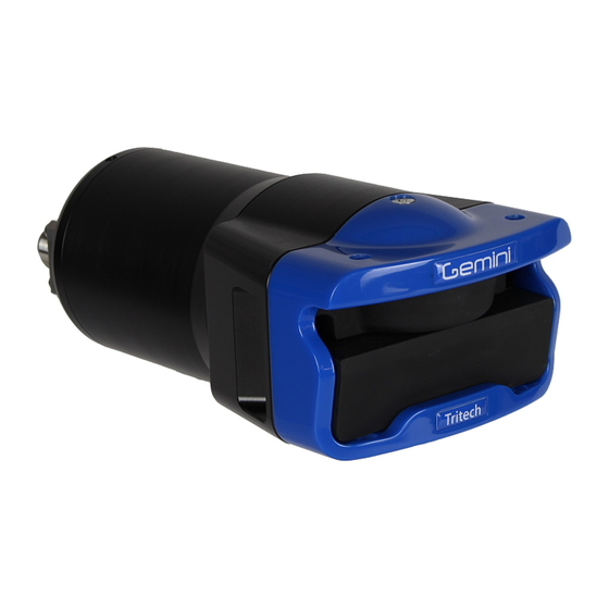
- Page 1 Gemini 720is Imaging Sonar Gemini 720is Imaging Sonar Product Manual Document: 0703-SOM-00002, Issue: 1 Document: 0703-SOM-00002, Issue: 1 © Tritech International Ltd.
- Page 2 Gemini 720is Imaging Sonar © Tritech International Ltd The copyright in this document is the property of Tritech International Ltd. The document is supplied by Tritech International Ltd on the understanding that it may not be copied, used, or disclosed to others except as authorised in writing by Tritech International Ltd.
-
Page 3: Table Of Contents
4.1. System Requirements ................. 23 4.2. Installing the Gemini Software ..............23 4.3. Configuring the Gemini ................24 4.3.1. Check the operation of the Gemini ........... 25 5. Gemini Software Operation ..................26 5.1. User Screen ....................26 5.1.1. Overview ..................26 5.1.2. - Page 4 A. Setting the computer IP address in Windows XP ............ 71 B. Setting the computer IP address in Windows 7 ............73 C. Setting the Gemini Device IP Address in Gemini Software ........75 D. Setting the Gemini Head IP Address in Seanet Pro ..........76 E.
-
Page 5: Help & Support
Gemini 720is Imaging Sonar Help & Support First please read this manual thoroughly (particularly the Troubleshooting section, if present). If a warranty is applicable, further details can be found in the Warranty Statement, 0080- STF-00139, available upon request. Tritech International Ltd can be contacted as follows:... -
Page 6: Warning Symbols
Gemini 720is Imaging Sonar Warning Symbols Throughout this manual the following symbols may be used where applicable to denote any particular hazards or areas which should be given special attention: Note This symbol highlights anything which would be of particular interest to the reader or provides extra information outside of the current topic. -
Page 7: Head Variations
1000m version 4000m version • Aluminium Housing • Titanium Housing The Gemini 720is is available with a wide variety of connectors fitted: • Single Seaconn 5506-1508 (Standard option) • Dual Seaconn 5506-1508 • Single Seaconn MC-BH-8M • Single Burton 5506-1508 •... -
Page 8: Introduction
1. Introduction 1.1. General Overview The Gemini 720is is a 2D imaging sonar. It is a multibeam sonar, offering a 120° field of view with update rates of up to 30Hz giving rapid feedback to the user (hardware is capable of 30Hz, Seanet Pro is limited to 15Hz). -
Page 9: Software Version
Introduction Gemini 720is Imaging Sonar Caution Power should only be applied to the MAIN port of the Gemini. The AUX port, if fitted, provides a regulated power supply - please refer to Section 2.1, “Gemini 720is” for more information. 1.4. Software Version... -
Page 10: Technical Specification
Gemini 720is Imaging Sonar 2. Technical Specification 2.1. Gemini 720is All dimensions are in mm, not to scale Acoustic Operating Frequency 720kHz Number of Channels Angular Resolution 1.0° acoustic, 0.5° effective Scanning Sector 120° Number of Beams Vertical Beamwidth 20° (tilted down 10°) Range 0.2m to 120m... -
Page 11: Hardware Installation & Configuration
(especially if they are not aluminium) they should be painted or lacquered with at least two or three coatings. Caution When deploying the aluminium version of the Gemini 720is, alloys containing copper such as brasses or bronze should be avoided. 1. Sound Velocity Probe 2. -
Page 12: Connector Maintenance Guidelines
Any water trapped in the connection could result in an electrical short. If the Gemini has two ports then the unused connector must have a blanking cap fitted prior to immersing in water. Failure to do this will cause permanent damage. -
Page 13: Sonar Head Pin-Out Diagrams
Ethernet RX+ Ethernet RX- Ethernet Tx+ DC + Ethernet Tx- DC Ground S11110 (1000m) or S11111 (4000m) Gemini 720is fitted with a single Seacon 55 series connector using Ethernet and VDSL communications. Bulkhead view Function Ethernet Rx+ Ethernet Rx- Ethernet Tx+... -
Page 14: Schilling Seanet Connector
Ethernet Rx+ Ethernet Rx- Ethernet Tx- Ethernet Tx+ 3.3.4. Single Titan Impulse MKS-310-FCR connector S11414 (1000m) only Gemini 720is fitted with a single Titan Impulse MKS-310-FCR connector using Ethernet communications only. Bulkhead view Function Ethernet Rx+ Ethernet RX- Ethernet Tx+... -
Page 15: Single Titan Impulse Mks(W)-307-Fcr Connector
3.3.6. Seacon 5506-1508 and Seacon 5506-1506 connectors S11127 (1000m) or S11128 (4000m) Gemini 720is fitted with two Seacon 55 series connectors. The main connector uses Ethernet communications with the auxiliary connector providing an additional Ethernet communication line and regulated 24V DC output. -
Page 16: Surface Adapter Pin-Out Diagrams
For all system types the connection to the surface computer or IT infrastructure from the Gemini Hub, Ethernet or VDSL adapter should be via a shielded Cat5e cable fitted with an RJ45 connector. The 72V VDSL Adapter Unit can also be... -
Page 17: Vdsl Adapter
Hardware Installation & Configuration Gemini 720is Imaging Sonar Sonar Head Connector Function Diagram Photograph Ethernet RX+ Ethernet RX - Ethernet TX+ DC + DC + Ethernet TX - DC Ground DC Ground not connected not connected not connected cable screen... - Page 18 Hardware Installation & Configuration Gemini 720is Imaging Sonar Sonar Head Connector Function Diagram Photograph DC Ground DC + not connected VDSL + VDSL - not connected cable screen Souriau UTS7147S VDSL DC Connector Function Diagram Photograph DC Ground DC +...
-
Page 19: An Example Ethernet Setup
Hardware Installation & Configuration Gemini 720is Imaging Sonar 3.5. An Example Ethernet Setup Test or bench setup for the Gemini Sonar system using Ethernet communications via the Ethernet adapter unit (Gemini 720is shown). Ethernet Adapter Computer CAT5 Patch Cable Gemini 720is... -
Page 20: An Example Vdsl Setup
Hardware Installation & Configuration Gemini 720is Imaging Sonar 3.6. An Example VDSL Setup Test or bench setup for the Gemini Sonar system using VDSL communications via the VDSL adapter unit (Gemini 720is shown). VDSL Adapter Computer CAT5 Patch Cable Gemini 720is... -
Page 21: An Example Rov Setup
Hardware Installation & Configuration Gemini 720is Imaging Sonar 3.7. An Example ROV Setup An example of connections for an ROV, with the Gemini Sonar system using VDSL communications via the VDSL adapter unit (Gemini 720is shown). VDSL Adapter Computer power supply... -
Page 22: Multiple Head Installation
Hub please refer to the Gemini Hub manual or contact Tritech International Ltd. It is also possible to link two Gemini 720is units together as long as at least one unit is fitted with dual Seacon connectors in the dual Ethernet configuration:... -
Page 23: Gemini Software Installation
Gemini 720is Imaging Sonar 4. Gemini Software Installation The Gemini head is supplied with software to control the functions of the sonar and to display the captured images. The software is supplied as an installer package which installs the software and a number of supporting files and documentation. -
Page 24: Configuring The Gemini
The Gemini software is then used to change the IP address of the Gemini. The third stage is to reset the IP address of the computer. The final stage is to check the operation of the Gemini on the network (by running the Gemini software and verifying that the Gemini head is able to communicate). -
Page 25: Check The Operation Of The Gemini
When the Gemini software is started, select the Advanced tab to show details of the connected Gemini and if it is able to communicate, it will be listed in the status window and automatically go online after five seconds. -
Page 26: Gemini Software Operation
5.1. User Screen 5.1.1. Overview The 120° cone in the middle of the display shows the sonar image that the Gemini Sonar is producing. Around this display are the most commonly used controls. On the upper left hand corner are the controls for starting the sonar imaging, starting the software logging of the images received from the sonar, replaying previously logged data, and capturing images. -
Page 27: Online Button
If the Online button is pressed while no heads are visible to the Gemini software, the following message will be displayed. Clicking OK will acknowledge the message, and the software will not go online. -
Page 28: Record Button
Gemini head, nor is it possible to open a file whilst another file is already playing. - Page 29 When replaying a log file, the filename, together with the date and time of recording, will be displayed at the bottom of the screen (below the Gemini data) in green text, for example: Frame Number and Speed Control Document: 0703-SOM-00002, Issue: 1 ©...
-
Page 30: Capture Screen
When clicked, the Capture Screen button will take a screenshot of the Gemini data view and write it to an image file. This image is stored in the Images subdirectory of the log data directory, with a filename of Gemini_nnnn.xxx, where nnnn is an incrementing index number for the image and xxx is the selected image format. -
Page 31: Invert Display (Up/Down)
For example, by default the first video file would be saved as C:\GeminiData \Images\Gemini_0001.wmv. When the video file has been captured, the Gemini software will display a message (as below) giving the name of the file. This message will be displayed for five seconds and then will close automatically. -
Page 32: Filter Selector
The magnification level can be changed between 1.5x (minimum magnification)and 40x (maximum magnification). Clicking within the Gemini data arc will lock the zoom at that point. Clicking outside of the arc will release the lock and the zoomed area will follow the mouse pointer. -
Page 33: Gain Control
When the mouse pointer is within the ‘cone’ on the sonar display (that is over the displayed sonar image), the indicators at the bottom right hand side of the screen will show the position of the mouse pointer relative to the origin of the display (that is relative to the Gemini Sonar). Document: 0703-SOM-00002, Issue: 1... -
Page 34: Measurements
The sonar will continue to operate, but will heat up more rapidly than if it was in water, and it may reach a temperature where it will automatically shut down to protect itself. If this happens, it will not be possible to communicate with or operate the Gemini until it has cooled to a safe temperature. -
Page 35: System Data
Gemini Sonar (or Sonars) connected to the system. More than one Gemini Sonar can be communicating at any one time and the Gemini software will display the images from up to a maximum of four of the sonars. -
Page 36: Configuration Options
Sonar Selection The Sonar ID of the Gemini Sonar is used to determine which sonar will be used as the source of images displayed by the software. The Sonar ID is available on the system data area of the Advanced screen, and should be entered in the Sonar box. - Page 37 The Compression control sets the level applied by the run length encoding; returns below this intensity percentage will be set to zero. The live image displayed by the Gemini software immediately shows the effect of the compression.
- Page 38 Data from external serial sensors can input to the software via a Gemini Hub, the computer COM Ports or via the additional serial ports on the Gemini unit itself. These options can be enabled/disabled using the provided drop-down menus. See Section 5.3, “Serial Data Input”...
-
Page 39: Application Settings
The Secondary logging directory selector allows the user to specify a second directory in which Gemini log data will be written to. For example, this may be used to write to a backup location. If both Primary and Secondary directories are specified a recorded log file will be written to both directories. - Page 40 Gemini Software Operation Gemini 720is Imaging Sonar Resolution The Resolution dropdown menu provides options for screenshot and video capture resolution. This can be used to increase or decrease the image/video size (width x height) as well as the quality. The list contains the following options: commonly used screen resolutions (i.e. 1920x1080) and a Screen (x) option, which is the current monitor resolution.
-
Page 41: Filter Settings
Gemini Software Operation Gemini 720is Imaging Sonar 5.2.4. Filter Settings The Filter Selector on the User screen selects one of three filters to be applied to the image before it is displayed. The Filter Setting section of the Configuration Options screen allows the settings of these three filters to be changed. -
Page 42: Device Network Settings
Appendix C, Setting the Gemini Device IP Address in Gemini Software describes how the Gemini network settings can be altered to allow it to work with a desired network. Once the head has been successfully configured it should not be necessary to change the settings again unless moving to a different infrastructure. -
Page 43: Target Tracking
The distance between the Distance Marker and Set Point is displayed in the bottom right of the Gemini data view (see image below). The displayed values are calculated as: Distance (X, Y) = (Distance Marker - Set Point) The Distance Marker range/ Y coordinate may be updated from an external sensor. - Page 44 Maximum Targets This sets an upper limit of the number of targets that will be considered for tracking. Setting this to a large number will increase the load on the computer CPU and may cause the Gemini software to slow down.
-
Page 45: Serial Data Input
The Reset Targets button will stop any tracking that is currently taking place. 5.3. Serial Data Input Data from external serial sensors can be input into the Gemini software and logged as part of the sonar image record. Document: 0703-SOM-00002, Issue: 1... -
Page 46: Sonars & Sensors
Gemini Software Operation Gemini 720is Imaging Sonar To enable data input to the system select Enabled for the COM Ports or Gemini Hub. The COM Ports drop-down list is for serial ports that are connected to the computer (either natively or through an RS232 to USB converter) and is also for configuration of the RS232 functionality of the Gemini Sonar head. -
Page 47: Gemini Hub
The Hubs tab shows the status information from any connected Gemini Hubs. Hub Setup Tab The Hub Setup tab allows configuration of the serial ports on the rear of the Gemini Hub to allow RS232 data to pass through to the Gemini software from external sensors. -
Page 48: Com Ports
5.3.3. COM Ports The COM Ports enables two extra tabs called Serial Setup and Sonar Ports from where all the serial communication (both connected to the PC and ports on the Gemini head) are configured. Serial setup The Serial Setup tab controls the serial communication being inputted and exported by the Gemini software. - Page 49 The incoming data string, check this against the chosen Decode if the data indicator is red. The Output COM Port section allows the user to export data from the Gemini software to third party applications. Changing the Encode option will alter the output. For more details on the data formats for each string, please refer to Appendix F, Gemini Software String Encode.
-
Page 50: Aux Power
The incoming data string, check this against the chosen Decode if the data indicator is red. 5.3.4. Aux Power The Aux Power will enable, or disable power to the Aux port of the Gemini 720is. Caution As the Aux port is powered by an internal regulator, the maximum power limit should never be exceeding. - Page 51 Gemini Software Operation Gemini 720is Imaging Sonar Example Layout Changing the position values as follows: Will arrange the sonar images in a circle: Note Turning off the range lines and text can improve the display. In this case, sonar 1 is looking forward while 2 and 3 are looking aft. There is no overlap and each sonar is displaying a full 120°...
-
Page 52: Offline Mode
Gemini Sonar was possible, and as described earlier in this manual. 5.6. Automatic Online Once the Gemini Sonar and the Gemini software have been configured so that they can communicate successfully, when the Gemini software is started it will automatically start imaging as soon as it detects the presence of that Sonar. -
Page 53: Settings Files
The Gemini software stores all the settings in the file C:\GeminiData\Settings \Gemini.xml. A backup of this file can be kept as a record of all the Gemini settings. When contacting Tritech International Ltd Technical Support it may be necessary to supply a copy of this file. -
Page 54: Seanet Pro Installation
Gemini 720is Imaging Sonar 6. Seanet Pro Installation 6.1. System requirements Minimum Recommended Processor 2GHz 2GHz dual core Graphics 3D hardware accelerated graphics card. Display 1280x1024 (32bit colour) 1600x1200 (32bit colour) Disk space Install is 20MB, greater than 160GB recommended for log files Networking 100Mbit·s... - Page 55 Setting the Gemini Head IP Address in Seanet Pro The final check to see if the correct changes have been made to the Gemini Sonar is to run Seanet Setup from the desktop icon to display the Node table. If the change of the sonar’s IP address has been successful, the sonar should be listed in the node window.
- Page 56 Seanet Pro Installation Gemini 720is Imaging Sonar Note In order to correctly run the Gemini head on a SCU the SCUv5, or later, is required. Contact Tritech International Ltd for more details of the SCUv5. Document: 0703-SOM-00002, Issue: 1 © Tritech International Ltd.
-
Page 57: Seanet Pro Operation
Seanet Pro Software Manual which is available online www.tritech.co.uk Before starting operations, run Seanet Setup to verify that the Gemini LAN is enabled and any connected devices, including the Gemini sonar, are detected. In Seanet Pro, the Gemini Sonar has been allocated the node range from 100 to 103. - Page 58 Once the Gemini LAN is enabled and a Gemini Sonar connected ensure that Seanet Pro is using its Setup Application. The Gemini will be displayed in the Seanet Setup Node Table. Click on Setup in the Action column to open the Gemini Cfg Setup dialog.
-
Page 59: Gemini Sonar Application
Gemini Sonar. Whenever a Medium Noise or High Noise setting is selected, on initial startup of the Gemini, the VDSL communications will take several seconds to find it’s optimum rate. During this period of rate adaption, the top-left of the Sonar screen will indicate the status text Acquiring…... -
Page 60: Sonar Settings
International Ltd mechanical sonar heads such as SeaKing and SeaPrince. However, the Gemini Sonar has a fixed scan sector of 120° and unlike the mechanical heads does not have option for scan sector size and position adjustments. Therefore these function controls have been omitted from the settings bar. -
Page 61: Application Tools
5. Scanned Area Indicator indicates, in the colour red, the size and position of the scan sector. This control will always indicate a fixed, forward 120° sector for the Gemini Sonar (or 130° for Gemini Narrow Beam Imager). - Page 62 Rng Cross, Rings On, Rings, Grid On - Display Grid line options. Sector On, Sector – Display a Sector overlay with left and right angular limit adjustment (in degrees). Rotation – Rotational offset to correct Sonar heading – (Disabled for Gemini Sonar). Document: 0703-SOM-00002, Issue: 1 © Tritech International Ltd.
- Page 63 Seanet Pro Operation Gemini 720is Imaging Sonar Installation Figure 7.5. This configures the location of the Sonar in the real world and enables the Geo-referencing of sonar targets on the sonar display. From Fixed Position If there is no GPS input, select this option and input the Sonar position in Latitude and Longitude co-ordinates (DegMin or DegMinSec format).
- Page 64 Seanet Pro Operation Gemini 720is Imaging Sonar or if the compass is connected to the Aux port of the sonar select Internal/Aux Compass. If the compass device has been connected through a COM port on the SCU or PC, or if a USBL system is in use then select Ship/USBL Compass.
- Page 65 Velocity of Sound This panel displays the Velocity of Sound value being used by the Gemini Sonar. The Gemini is fitted with a Velocimeter which can be enabled/disabled in the Gemini Cfg Setup dialog.
- Page 66 If Auto VOS is “OFF” then the Velocity of Sound used is based on the Manual VOS applied in the ‘Environment’ (e.g. click on ‘Settings’ – ‘Environment’ in Seanet Toolbar). Note The Gemini Sonar will apply Manual VOS in steps of 3.2m·s , starting from the minimum limit of 1400m·s .
-
Page 67: Outputting Data Via Remv4
Gemini 720is Imaging Sonar 7.3. Outputting data via REMV4 With the Gemini 720is setup to process an incoming serial data stream (see Section 7.1, “Seanet Setup for Gemini” for details) the incoming data can be set to output to external software packages using the REMV4 software. -
Page 68: Maintenance
VOS sensor. The mechanical interface between the bulkhead connectors and housing elements should also be inspected. It is recommended that Gemini units be returned to Tritech as part of a regular maintenance schedule. An annual return is highly recommended, but this can be lengthened, or shortened, by various factors: •... -
Page 69: Troubleshooting
The software reports that no sonars are detected VDSL System – Check the VDSL link light on the Gemini Hub (note that it may take up to 1 minute to establish a stable VDSL link). If there is no VDSL link light then check all cabling between Gemini Hub and the sonar and verify that the sonar is powered correctly with appropriate voltage at the sonar. - Page 70 All Systems – Some poor quality PC network cards have problems with the large data rate from the Gemini sonar and drop a significant amount of packets. If you have large packet loss, try updated network card drivers and a different brand of network card. Also check that the PC and graphics chipset meet the minimum spec.
-
Page 71: Setting The Computer Ip Address In Windows Xp
Gemini 720is Imaging Sonar Appendix A. Setting the computer IP address in Windows XP The following instructions apply to a computer running Windows XP, though the sequence for other operating systems will be similar. If the computer is connected to a network already, disconnect it from that network. - Page 72 Setting the computer IP address in Windows XP Gemini 720is Imaging Sonar Make a note of the settings as currently used by the computer; these will be needed to restore the computer to any existing network. Refer to the appropriate section of this manual for the correct IP address to use.
-
Page 73: Setting The Computer Ip Address In Windows 7
Gemini 720is Imaging Sonar Appendix B. Setting the computer IP address in Windows 7 The following instructions apply to a computer running Windows 7, though the sequence for other operating systems will be similar. Disconnect the computer from any existing network. - Page 74 Setting the computer IP address in Windows 7 Gemini 720is Imaging Sonar A list of attached network devices should now present itself. Find the one which the Gemini head is to be connected to and double-click on it. The Local Area Connection Properties dialog should be displayed. Find the entry labelled Internet Protocol Version 4 (TCP/IPv4), select it and then click on the Properties button.
-
Page 75: Setting The Gemini Device Ip Address In Gemini Software
Gemini devices should be disconnected. Once the ID of the Gemini has been entered at the top of the screen, the details for the new IP address can be entered. Three items need to be entered, the Device ID (to ensure that the correct Gemini is being altered), the new IP Address and the new Subnet Mask. -
Page 76: Setting The Gemini Head Ip Address In Seanet Pro
Ensure that the Gemini is connected directly to the computer. In the Selected Sonar drop-down control, ensure that the correct Gemini is selected. The current Sonar IP Address and Subnet Mask are displayed on the left hand side of the form. - Page 77 IP Address for details of how to do this). Once communication has been re-established the following screen shows the sonar is connected: Returning to Gemini LAN from the Setup menu should confirm that the changes have been made successfully. Document: 0703-SOM-00002, Issue: 1...
-
Page 78: Gemini Software String Decode
Gemini 720is Imaging Sonar Appendix E. Gemini Software String Decode The Gemini Software is capable of handling input from various different types of sensors using the following standard strings: Depth strings Name Description Format/Examples Digi Parascientific Digiquartz 000.0 (depth sensor) - Page 79 Gemini Software String Decode Gemini 720is Imaging Sonar Heading, Position and Time strings Name Description Format/Examples CDL1 Heading, Pitch, Roll Haaa.aP+ccc.ccR+eee.eeT... GPGGA GPS position $GPGGA... GPGGA ZDA GPS position and UTC time $GPGGA... $GPZDA... $GPZDA UTC Time $GPZDA... HEHDT Heading $HEHDT...
-
Page 80: Gemini Software String Encode
Gemini 720is Imaging Sonar Appendix F. Gemini Software String Encode The Gemini Software is capable of outputting different data strings depending on the requirement of the user: Target tracking strings Name Description Format/Examples PTRITAR Basic target tracking output string $PTRITAR, DDMMYYYY, HHMMSS, (Gemini 720i / 720id / NBI) 1, 0.0, 0.0, CS... -
Page 81: Glossary
Gigabyte = 1000MB Gemini Unless specified this can refer to any of the multibeam sonars in the Gemini range by Tritech International Ltd such as the Gemini Imager (720id), Narrow Beam Imager or Gemini Profiler (620pd). Gemini Hub A rack mountable device capable of driving 2 Gemini sonars and multiple serial sensors and outputting the data to a PC network. - Page 82 Glossary Gemini 720is Imaging Sonar Multibeam A sonar which forms multiple "beams" of sound so it can update in real time and does not have to perform a full scan like a traditional sonar. Personal Computer The standard filename extension for Portable Network Graphics - a bitmapped image format employing lossless compression.
Need help?
Do you have a question about the 720is and is the answer not in the manual?
Questions and answers