
Related Manuals for Gemini 720i


Summary of Contents for Gemini 720i
- Page 1 Gemini Imaging Sonar Gemini Imaging Sonar Product Manual Document: 0685-SOM-00001, Issue: 11 Document: 0685-SOM-00001, Issue: 11 © Tritech International Ltd.
- Page 2 Gemini Imaging Sonar © Tritech International Ltd The copyright in this document is the property of Tritech International Ltd. The document is supplied by Tritech International Ltd on the understanding that it may not be copied, used, or disclosed to others except as authorised in writing by Tritech International Ltd.
-
Page 3: Table Of Contents
4.1. System Requirements ................. 24 4.2. Installing the Gemini Software ..............24 4.3. Configuring the Gemini ................24 4.3.1. Check the operation of the Gemini ........... 25 5. Gemini Software Operation ..................26 5.1. User Screen ....................26 5.1.1. Overview ..................26 5.1.2. - Page 4 A. Setting the computer IP address in Windows XP ............ 68 B. Setting the computer IP address in Windows 7 ............70 C. Setting the Gemini Device IP Address in Gemini Software ........72 D. Setting the Gemini Head IP Address in Seanet Pro ..........73 E.
-
Page 5: Help & Support
Gemini Imaging Sonar Help & Support First please read this manual thoroughly (particularly the Troubleshooting section, if present). If a warranty is applicable, further details can be found in the Warranty Statement, 0080- STF-00139, available upon request. Tritech International Ltd can be contacted as follows:... -
Page 6: Warning Symbols
Gemini Imaging Sonar Warning Symbols Throughout this manual the following symbols may be used where applicable to denote any particular hazards or areas which should be given special attention: Note This symbol highlights anything which would be of particular interest to the reader or provides extra information outside of the current topic. -
Page 7: Included Equipment
5. Blanking cap for unused connector (may be included in an accessories kit with spare O- rings) Also provided will be a sonar head flight case, Gemini software, Seanet Pro software and documentation. The latest documentation and software updates are available through www.tritech.co.uk. -
Page 8: Head Variations
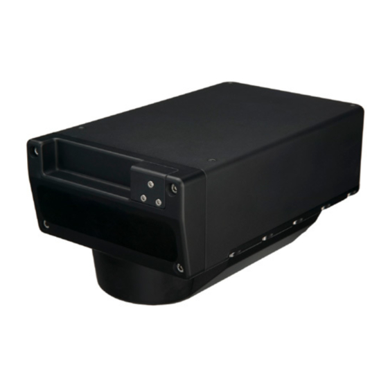
Gemini Imaging Sonar Head Variations Gemini 720i (300m depth rating) Impulse Connectors VDSL Ethernet Gemini 720id (4000m depth rating) Impulse Connectors Burton Connectors VDSL Ethernet Auxiliary Main Finished in titanium (silver/grey) or aluminium (black anodised) Document: 0685-SOM-00001, Issue: 11 © Tritech International Ltd. -
Page 9: Introduction
1. Introduction 1.1. General Overview The Gemini is a 2D imaging sonar. It is a multibeam sonar, offering a 120° field of view with update rates of up to 30Hz giving rapid feedback to the user (hardware is capable of 30Hz, Seanet Pro is limited to 15Hz). -
Page 10: Software Version
Introduction Gemini Imaging Sonar Caution Power should only be supplied on one connector at a time. 1.4. Software Version Note The instructions within this manual apply to software version 2.00.13 onwards. Screenshots and images wihin the software may differ slightly from the ones used within this manual. -
Page 11: Technical Specification
Gemini Imaging Sonar 2. Technical Specification 2.1. Gemini 720i M5 x 0.8 Not to scale, dimensions in mm. Acoustic Operating Frequency 720kHz Number of Channels Angular Resolution 1.0° acoustic, 0.5° effective Scanning Sector 120° Number of Beams Vertical Beamwidth 20°... -
Page 12: Gemini 720Id
Technical Specification Gemini Imaging Sonar Physical Weight 3.9kg air, 1.2kg water Depth Rating 300m Materials & Finish Aluminium alloy (6082T6) hard anodised Operating Temperature -10 to 35°C Storage Temperature -20 to 50°C 2.2. Gemini 720id Ø140 Ø145 Not to scale, dimensions in mm. -
Page 13: Vdsl Adapter
Technical Specification Gemini Imaging Sonar Physical Property Aluminium Body Titanium Body Weight 8kg air, 3.5kg water 12kg air, 7.5kg water Depth Rating 4000m 4000m Materials Aluminium alloy (6082T6) Titanium (6 AL-4V) Finish Hard anodised Bead blasted Operating Temperature -10 to 35°C Storage Temperature -20 to 50°C... -
Page 14: Ethernet Adapter
Technical Specification Gemini Imaging Sonar 2.4. Ethernet Adapter Not to scale, dimensions in mm. Weight 1.1kg Materials Enclosure: Aluminium alloy (AC-44300), Connectors: thermoplastic Finish Powder Coated Operating Temperature 5 to 35°C Storage Temperature -20°C to 50°C Supply Voltage 22 - 75V DC... -
Page 15: Hardware Installation & Configuration
10° which should be taken into account when mounting the Sonar. For the 720i there are 4 tapped M5 holes (10mm deep) on the top surface that are to be used for mounting the sonar. -
Page 16: Sonar Head Pin-Out (Impulse Titan Connector)
Any water trapped in the connection could result in an electrical short. If the Gemini has two ports then the unused connector must have a blanking cap fitted prior to immersing in water. Failure to do this will cause permanent damage. -
Page 17: Impulse Titan Mks-310-Fcr (Ethernet Port)
Hardware Installation & Configuration Gemini Imaging Sonar 3.3.1. Impulse Titan MKS-310-FCR (Ethernet Port) Function Diagram Photograph Ethernet RX + Ethernet RX - Ethernet TX + DC + DC + Ethernet TX- DC Ground DC Ground TTL Ground TTL IN Impulse Titan MKS-310-FCR 3.3.2. -
Page 18: Burton 5506-1508 (Main Port)
Hardware Installation & Configuration Gemini Imaging Sonar 3.4.1. Burton 5506-1508 (Main Port) Function Diagram Ethernet RX + Ethernet RX - Ethernet TX + DC + VDSL + Ethernet TX - DC Ground (0V) VDSL - 5506-1508 3.4.2. Burton 5506-1506 (Auxiliary Port) -
Page 19: Vdsl Cable
An RS232 serial connection or TTL connection is possible to enable the use of an auxiliary device or sensor connected in series with the Gemini head. A cable to connect to the Auxiliary port is available from Tritech International Ltd with the following specification:... -
Page 20: Surface Adapter Pin-Out Diagrams
3.6. Surface Adapter Pin-out Diagrams Note For all system types the connection to the surface computer or IT infrastructure from the Gemini Hub, Ethernet or VDSL adapter should be via a shielded Cat5e cable fitted with an RJ45 connector. 3.6.1. Ethernet Adapter... -
Page 21: Vdsl Adapter
DC + not connected not connected Souriau UTS7124P 3.7. An Example Ethernet Setup Test or bench setup for the Gemini Sonar system using Ethernet communications via the Ethernet adapter unit (Gemini 720i shown). Document: 0685-SOM-00001, Issue: 11 © Tritech International Ltd. -
Page 22: An Example Vdsl Setup
Hardware Installation & Configuration Gemini Imaging Sonar 3.8. An Example VDSL Setup Test or bench setup for the Gemini Sonar system using VDSL communications via the VDSL adapter unit (Gemini 720i shown). 3.9. An Example ROV Setup An example of connections for an ROV, with the Gemini Sonar system using VDSL communications via the VDSL adapter unit (Gemini 720i shown). -
Page 23: Multiple Head Installation
Gemini Imaging Sonar 3.10. Multiple Head Installation It is possible to control and display up to four Gemini heads from one computer using the Gemini software. In order to do this extra hardware will be required to connect the extra... -
Page 24: Gemini Software Installation
The Gemini software is then used to change the IP address of the Gemini. The third stage is to reset the IP address of the computer. The final stage is to check the operation of the Gemini on the network (by running the Gemini software and verifying that the Gemini head is able to communicate). -
Page 25: Check The Operation Of The Gemini
When the Gemini software is started, select the Advanced tab to show details of the connected Gemini and if it is able to communicate, it will be listed in the status window and automatically go online after five seconds. -
Page 26: Gemini Software Operation
5.1. User Screen 5.1.1. Overview The 120° cone in the middle of the display shows the sonar image that the Gemini Sonar is producing. Around this display are the most commonly used controls. On the upper left hand corner are the controls for starting the sonar imaging, starting the software logging of the images received from the sonar, replaying previously logged data, and capturing images. -
Page 27: Online Button
If the Online button is pressed while no heads are visible to the Gemini software, the following message will be displayed. Clicking OK will acknowledge the message, and the software will not go online. -
Page 28: Record Button
163002_IMG.ECD in the directory C:\GeminiData \LD20141018. The software will automatically create any directories needed for recording. 5.1.4. Player Controls The player controls manage the replay of Gemini data previously recorded by the software. Document: 0685-SOM-00001, Issue: 11 © Tritech International Ltd. - Page 29 Gemini head, nor is it possible to open a file whilst another file is already playing.
-
Page 30: Capture Screen
When clicked, the Capture Screen button will take a screenshot of the Gemini data view and write it to an image file. This image is stored in the Images subdirectory of the log data directory, with a filename of Gemini_YYYY-MM-DD-HHmmSS.xxx, where: •... -
Page 31: Record Video
• xxx: Video file format. See Section 5.2.3, “Application Settings” for the video format and resolution options. When the video file has been captured, the Gemini software will display a message (as below) giving the name of the file. This message will be displayed for five seconds and then will close automatically. -
Page 32: Draw Grid
The magnification level can be changed between 1.5x (minimum magnification)and 40x (maximum magnification). Clicking within the Gemini data arc will lock the zoom at that point. Clicking outside of the arc will release the lock and the zoomed area will follow the mouse pointer. -
Page 33: Sound Velocity Indicator
5.1.14. Gain Assist By default this is turned on as indicated by green text. When turned on the Gemini will automatically reduce a high gain setting on range lines where bright targets are observed. This improves the clarity of the target, but can give the effect of dark bands in the background image. -
Page 34: Range Control
(that is relative to the Gemini Sonar). The pointer position is expressed as a range / bearing pair, and as a Cartesian co-ordinate (X, Y). -
Page 35: Warnings
5.1.19. Warnings Out of water If the Gemini detects that it is not immersed in water, the warning “Out of water” will be displayed in the centre of the scan image: The sonar will continue to operate at full power during a 20 minute countdown period. During the countdown period, toggling the Online button will reset the timer back to the start or immersing the sonar back into water will clear the warning. -
Page 36: Advanced Screen
Gemini Sonar (or Sonars) connected to the system. More than one Gemini Sonar can be communicating at any one time and the Gemini software will display the images from up to a maximum of four of the sonars. -
Page 37: Configuration Options
Sonar Selection The Sonar ID of the Gemini Sonar is used to determine which sonar will be used as the source of images displayed by the software. The Sonar ID is available on the system data area of the Advanced screen, and should be entered in the Sonar box. - Page 38 The Compression control sets the level applied by the run length encoding; returns below this intensity percentage will be set to zero. The live image displayed by the Gemini software immediately shows the effect of the compression.
- Page 39 Serial Inputs Data from external serial sensors can input to the software via a Gemini Hub or the computer COM Ports. These options can be enabled/disabled using the provided drop-down menus.
-
Page 40: Application Settings
The Secondary logging directory selector allows the user to specify a second directory in which Gemini log data will be written to. For example, this may be used to write to a backup location. If both Primary and Secondary directories are specified a recorded log file will be written to both directories. - Page 41 Gemini Imaging Sonar Enable Auto Logging This option will enable the Gemini software to start logging data immediately upon start up and when the software goes online, without any additional user intervention. It will use the Primary and Secondary locations for storage and use the ECD file format for storage.
-
Page 42: Filter Settings
Gemini Software Operation Gemini Imaging Sonar Reset to Defaults Pressing the Reset to Defaults button returns the software settings to the default values. Caution should be taken as this will overwrite all user settings changes. 5.2.4. Filter Settings The Filter Selector on the User screen selects one of three filters to be applied to the image before it is displayed. -
Page 43: Device Network Settings
Appendix C, Setting the Gemini Device IP Address in Gemini Software describes how the Gemini network settings can be altered to allow it to work with a desired network. Once the head has been successfully configured it should not be necessary to change the settings again unless moving to a different infrastructure. -
Page 44: Target Tracking
Distance Marker panel. The Distance Marker line width can be set by entering a value into the Marker Width field. In the Gemini data view, each marker can be clicked and dragged to a new position. The distance measurement will continuously update and reflect the distance between the two markers. - Page 45 Note Although both options will only be displayed, the Detect + Track option will only be available for selection if a Gemini 720is has been detected. The Target Tracking method can be selected using the drop down selection on the Tracking Mode box.
- Page 46 Maximum Targets This sets an upper limit of the number of targets that will be considered for tracking. Setting this to a large number will increase the load on the computer CPU and may cause the Gemini software to slow down.
- Page 47 Gemini Software Operation Gemini Imaging Sonar Active Range Window and Active Bearing Window These settings set up a mask around a tracked target. As long as the target moves within the mask from one instance to the next the target will remain tracked. If the target moves too quickly tracking will cease.
-
Page 48: Serial Data Input
To enable data input to the system select Enabled for either (or both) of the COM Ports or Gemini Hub. The COM Ports drop-down list is for serial ports that are connected to the computer (either natively or through an RS232 to USB converter) and is also for configuration of the RS232 functionality of the Gemini Sonar head. -
Page 49: Gemini Hub
The Hubs tab shows the status information from any connected Gemini Hubs. Hub Setup Tab The Hub Setup tab allows configuration of the serial ports on the rear of the Gemini Hub to allow RS232 data to pass through to the Gemini software from external sensors. -
Page 50: Com Ports
The incoming data string, check this against the chosen Decode if the data indicator is red. Gemini RS232 The ports on the rear of any connected Gemini heads. This data can be Ports decoded as per the computer COM ports or the data can be routed as an output from one of the computer COM ports (if the data is required on an second computer, for example). -
Page 51: Multiple Head Operation
Gemini Imaging Sonar 5.4. Multiple Head Operation Note The following instructions refer to a Gemini Sonar with a 120° swathe. Other products within the Gemini range may have differing swathes, but the same basic principles described apply. The number of heads connected to a system can be selected using the drop-down list on the right-hand pane of the Advanced screen. - Page 52 Gemini Software Operation Gemini Imaging Sonar Note Turning off the range lines and text can improve the display. In this case, sonar 1 is looking forward while 2 and 3 are looking aft. There is no overlap and each sonar is displaying a full 120° arc.
-
Page 53: Offline Mode
The Gemini software stores all the settings in the file C:\GeminiData\Settings \Gemini.xml. A backup of this file can be kept as a record of all the Gemini settings. When contacting Tritech International Ltd Technical Support it may be necessary to supply a copy of this file. -
Page 54: Keyboard Shortcuts
Gemini Software Operation Gemini Imaging Sonar 1. Shut down the Gemini software. 2. Delete (or rename) the C:\GeminiData\Settings\Gemini.xml file. 3. Copy the Factory.xml file into the location C:\GeminiData\Settings and rename it to Gemini.xml 4. Start the Gemini software. 5.8. Keyboard Shortcuts A number of keyboard shortcuts are available for commonly used activities. -
Page 55: Seanet Pro Installation
Setting the Gemini Head IP Address in Seanet Pro The final check to see if the correct changes have been made to the Gemini Sonar is to run Seanet Setup from the desktop icon to display the Node table. If the change of the sonar’s IP address has been successful, the sonar should be listed in the node window. -
Page 56: Seanet Pro Operation
Seanet Pro Software Manual which is available online www.tritech.co.uk Before starting operations, run Seanet Setup to verify that the Gemini LAN is enabled and any connected devices, including the Gemini sonar, are detected. In Seanet Pro, the Gemini Sonar has been allocated the node range from 100 to 103. - Page 57 ‘OK’ on the main form to upload these changes into the Sonar. Once the Gemini LAN is enabled and a Gemini Sonar connected and displayed in the Seanet Setup Node Table click on Setup in the Action column to open the Gemini Cfg Setup dialog.
-
Page 58: Gemini Sonar Application
International Ltd mechanical sonar heads such as SeaKing and SeaPrince. However, the Gemini Sonar has a fixed scan sector of 120° and unlike the mechanical heads does not have option for scan sector size and position adjustments. Therefore these function controls have been omitted from the settings bar. -
Page 59: Application Tools
5. Scanned Area Indicator indicates, in the colour red, the size and position of the scan sector. This control will always indicate a fixed, forward 120° sector for the Gemini Sonar (or 130° for Gemini Narrow Beam Imager). - Page 60 Seanet Pro Operation Gemini Imaging Sonar Markers Figure 7.5. Adds A and B markers onto the sonar display, the range and bearing to each marker & separation and relative bearing are shown. Click on the symbol to deploy on the Marker panel and that marker symbol will be dropped at the Origin (0, 0) on the Sonar display.
- Page 61 Gemini Imaging Sonar Sector On, Sector – Display a Sector overlay with left and right angular limit adjustment (in degrees). Rotation – Rotational offset to correct Sonar heading – (Disabled for Gemini Sonar). Installation Figure 7.8. This configures the location of the Sonar in the real world and enables the Geo-referencing of sonar targets on the sonar display.
- Page 62 Seanet Pro Operation Gemini Imaging Sonar Heading Use this option to select the source of the heading data. If using a sonar which contains an internal heading and compass device or if the compass is connected to the Aux port of the sonar select Internal/Aux Compass.
- Page 63 Velocity of Sound This panel displays the Velocity of Sound value being used by the Gemini Sonar. The Gemini is fitted with a Velocimeter which can be enabled/disabled in the Gemini Cfg Setup dialog.
- Page 64 If Auto VOS is “OFF” then the Velocity of Sound used is based on the Manual VOS applied in the ‘Environment’ (e.g. click on ‘Settings’ – ‘Environment’ in Seanet Toolbar). Note The Gemini Sonar will apply Manual VOS in steps of 3.2m·s , starting from the minimum limit of 1400m·s .
-
Page 65: Maintenance
VOS sensor. The mechanical interface between the bulkhead connectors and housing elements should also be inspected. It is recommended that Gemini units be returned to Tritech as part of a regular maintenance schedule. An annual return is highly recommended, but this can be lengthened, or shortened, by various factors: •... -
Page 66: Troubleshooting
The software reports that no sonars are detected VDSL System – Check the VDSL link light on the Gemini Hub (note that it may take up to 1 minute to establish a stable VDSL link). If there is no VDSL link light then check all cabling between Gemini Hub and the sonar and verify that the sonar is powered correctly with appropriate voltage at the sonar. - Page 67 All Systems – Some poor quality PC network cards have problems with the large data rate from the Gemini sonar and drop a significant amount of packets. If you have large packet loss, try updated network card drivers and a different brand of network card. Also check that the PC and graphics chipset meet the minimum spec.
-
Page 68: Setting The Computer Ip Address In Windows Xp
Gemini Imaging Sonar Appendix A. Setting the computer IP address in Windows XP The following instructions apply to a computer running Windows XP, though the sequence for other operating systems will be similar. If the computer is connected to a network already, disconnect it from that network. - Page 69 Setting the computer IP address in Windows XP Gemini Imaging Sonar Make a note of the settings as currently used by the computer; these will be needed to restore the computer to any existing network. Refer to the appropriate section of this manual for the correct IP address to use.
-
Page 70: Setting The Computer Ip Address In Windows 7
Gemini Imaging Sonar Appendix B. Setting the computer IP address in Windows 7 The following instructions apply to a computer running Windows 7, though the sequence for other operating systems will be similar. Disconnect the computer from any existing network. - Page 71 Setting the computer IP address in Windows 7 Gemini Imaging Sonar A list of attached network devices should now present itself. Find the one which the Gemini head is to be connected to and double-click on it. The Local Area Connection Properties dialog should be displayed. Find the entry labelled Internet Protocol Version 4 (TCP/IPv4), select it and then click on the Properties button.
-
Page 72: Setting The Gemini Device Ip Address In Gemini Software
Gemini devices should be disconnected. Once the ID of the Gemini has been entered at the top of the screen, the details for the new IP address can be entered. Three items need to be entered, the Device ID (to ensure that the correct Gemini is being altered), the new IP Address and the new Subnet Mask. -
Page 73: Setting The Gemini Head Ip Address In Seanet Pro
Ensure that the Gemini is connected directly to the computer. In the Selected Sonar drop-down control, ensure that the correct Gemini is selected. The current Sonar IP Address and Subnet Mask are displayed on the left hand side of the form. - Page 74 IP Address for details of how to do this). Once communication has been re-established the following screen shows the sonar is connected: Returning to Gemini LAN from the Setup menu should confirm that the changes have been made successfully. Document: 0685-SOM-00001, Issue: 11...
-
Page 75: Gemini Software String Decode
Gemini Imaging Sonar Appendix E. Gemini Software String Decode The Gemini Software is capable of handling input from various different types of sensors using the following standard strings: Depth strings Name Description Format/Examples Digi Parascientific Digiquartz 000.0 (depth sensor) SonDepth Depth $SONDEP... - Page 76 Gemini Software String Decode Gemini Imaging Sonar Heading, Position and Time strings Name Description Format/Examples CDL1 Heading, Pitch, Roll Haaa.aP+ccc.ccR+eee.eeT... GPGGA GPS position $GPGGA... GPGGA ZDA GPS position and UTC time $GPGGA... $GPZDA... $GPZDA UTC Time $GPZDA... HEHDT Heading $HEHDT...
-
Page 77: Glossary
Gigabyte = 1000MB Gemini Unless specified this can refer to any of the multibeam sonars in the Gemini range by Tritech International Ltd such as the Gemini Imager (720id), Narrow Beam Imager or Gemini Profiler (620pd). Gemini Hub A rack mountable device capable of driving 2 Gemini sonars and multiple serial sensors and outputting the data to a PC network. - Page 78 The software supplied by Tritech International Ltd which is capable of running all the sonar devices. Transistor Transistor Logic - superfluous terminology intended to mean a signal that can be input to the Gemini to trigger advanced functions. Transmit (data) Universal Serial Bus.
- Page 79 Glossary Gemini Imaging Sonar Velocity of Sound Windows Media Video - a compression format for several proprietary codecs developed by Microsoft for storing video files. Document: 0685-SOM-00001, Issue: 11 © Tritech International Ltd.
Need help?
Do you have a question about the 720i and is the answer not in the manual?
Questions and answers