Advertisement
Quick Links
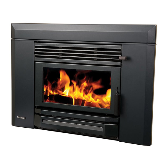
SPECIFICATION & INSTALLATION GUIDE FOR
MASPORT LE4000 PROVINCIAL BUILT-IN FIRE,
NEW ZEALAND MODEL
20.03.2012
Manufactured in New Zealand by:
GLEN DIMPLEX AUSTRALASIA LIMITED
P.O. Box 58 473, Botany
Auckland 2163
Ph: 0800 666 2824
Fax: 09 274 8472
Email: sales@glendimplex.co.nz
Web: www.glendimplex.co.nz
Part. No. 593398
1
Advertisement

Subscribe to Our Youtube Channel
Related Manuals for Masport LE4000


Summary of Contents for Masport LE4000
- Page 1 SPECIFICATION & INSTALLATION GUIDE FOR MASPORT LE4000 PROVINCIAL BUILT-IN FIRE, NEW ZEALAND MODEL Manufactured in New Zealand by: GLEN DIMPLEX AUSTRALASIA LIMITED P.O. Box 58 473, Botany Auckland 2163 Ph: 0800 666 2824 Fax: 09 274 8472 Email: sales@glendimplex.co.nz Web: www.glendimplex.co.nz 20.03.2012...
- Page 2 CONTENTS ZERO CLEARANCE BOX (SHIELDING BOX) KIT...
- Page 3 The model LE4000 Provincial has been tested to demonstrate compliance with current general emission requirements in New Zealand, but some areas have stricter limits. So check the...
- Page 4 KEEP FURNITURE AND DRAPES WELL AWAY FROM THE STOVE. NOTE The following instructions cover the installation of the model LE4000 Provincial Built-In Fire to be installed when no conventional masonry chimney is available. The woodfire will need a ‘zero clearance’ metal shielding box, ‘zero clearance’ fascia with top & bottom ventilated rails and special ‘zero clearance’...
-
Page 5: Floor Plan
STANDARD INSTALLATIONS- FLOOR TO CEILING ENCLOSURE: Inspect the house construction at the proposed installation position to verify that the flue shield (250mm diameter, plus 25mm clearance all around) can pass right up through the ceiling space without requiring the removal of essential roof or ceiling support beams. The flue cen- terline will be 271 mm out from the rear wall and it must be at least 730mm distant from any side wall. - Page 6 For durability of finishes and surfaces you should contact the relevant manufacturer for their specifications. Masport accepts no responsibility for the deterioration of surfaces or finishes. It is usually convenient to carry the heat-proof material right up to ceiling level. At the lower edge, drill (4.5 mm diameter) into the metal support angle through the holes in the top...
- Page 7 Cement tiles or slate to the top of the floor protector. The part inside the enclosure will not be visible and therefore does not need complete coverage. It is necessary to fix the finishing layer only under the support rails in this area. The visible edges of the floor protector are best finished with wooden trim or tiles.
- Page 8 If necessary, replace the electrical connections at the rear of the fan switch (see installation manual) and ensure that the earth wire is connected to the post behind the Masport badge on the left fascia upright.
- Page 9 Fig. 7...
- Page 10 Fig. 8 INSTALLATION ON COMBUSTIBLE FLOOR WITH MANTLE SHELF Fig. 9 INSTALLATION ON CONCRETE FLOOR WITH MANTLE SHELF...
- Page 11 Fig. 10 INSTALLATION - ELEVATED WITHOUT MANTLE SHELF Fig. 11 INSTALLATION ON COMBUSTIBLE FLOOR WITHOUT MANTLE...
- Page 12 HEIGHTS OF FLUE PIPE & CASINGS FOR STANDARD CASING COVER & COWL & TOP FLUE PIPE SPAC- ER BRACKET BY GLEN DIMPLEX FALSE CHIMNEY VENTED THROUGH 150-350 CASING COVER Fig. 12 HEIGHTS OF FLUE PIPE & CASINGS FOR STANDARD CASING COVER & COWL & TOP FLUE PIPE SPAC- ER BRACKET BY GLEN DIMPLEX FALSE CHIMNEY VENTED THROUGH SIDE VENT Fig.
-
Page 13: Hearth Requirements
HEARTH REQUIREMENTS: An insulating floor protector (hearth) is required. The minimum requirement for an insulating floor protector (hearth) is one layer of 6mm thick ‘PROMATECT H’, SUPALUX, or ETERPAN LD (or simi- lar with a heat transition coefficient of 5 W/m³ K), and a layer of tiles or slate. This will give a thick- ness of approximately 14mm, and the extension from the face of the glass must be at least 441mm (or 440mm from fireplace surround) if the floor protector is flush with the surrounding heat sensitive material. -
Page 14: Maintenance
ELECTRICAL INSTALLATION ALL ELECTRICAL WORK MUST BE CARRIED OUT BY A LICENCED REGISTERED ELECTRICIAN. THE FAN IS TO BE PERMANENTLY CONNECTED TO THE MAINS SUPPLY WITH NO PERIPHERAL CONTROLS. THIS MEANS, THERE MUST NOT BE A PLUG AND SOCKET ARRANGEMENT. IN ORDER TO COMPLY WITH THE NEW ZEALAND ELECTRICAL STANDARDS, AN ISOLATION SWITCH IS NEEDED FOR ISOLATING THE FAN FROM THE SOURCE OF POWER. - Page 15 SLIM AND WIDE FASCIA ASSEMBLY & INSTALLATION FOR LE4000 PROVINCIAL INSERTS If the fascia is not assembled use steps 1-4 to put together fascia components. Use steps 5 & 6 to attach fascia to firebox cabinet / casing. Lay the fascia panels flat, face down on something soft so they won’t scratch.
Need help?
Do you have a question about the LE4000 and is the answer not in the manual?
Questions and answers