Table of Contents
Advertisement
Owners &
Installation
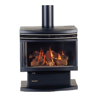
Monaco
Gas Fires
PLEASE KEEP THESE INSTRUCTIONS
FOR FUTURE REFERENCE
WARNING
Improper installation, adjustment, alteration,
service or maintenance can cause injury or
property damage.
For assistance or additional information
consult an authorized technichian, or your
Masport Gas Fire Dealer.
FOR YOUR SAFETY
Do not store or use gasoline or other
flammable vapours and liquids in the vicinity
of this appliance
Installation and service must be performed by
authorized personnel.
Metal Fab Industies Limited - New Zealand
PO Box 58 473
Greenmount
Auckland
FOR YOUR SAFETY
What to do if you smell gas
•
Do not try to light any
appliance
•
Do not touch any
electrical switch
•
Do not use any phone
in your building
•
Immediately close the
shutoff valve behind the
heater
•
Call the technician
Metal Fab PTY - Australia
Unit 2, 205 Abbotts Road
Dendenong South
Victoria 3175
591558
Advertisement
Table of Contents

Related Manuals for Masport Monaco


Summary of Contents for Masport Monaco
- Page 1 For assistance or additional information • Do not touch any consult an authorized technichian, or your electrical switch Masport Gas Fire Dealer. • Do not use any phone FOR YOUR SAFETY in your building • Do not store or use gasoline or other...
- Page 2 THE INSTRUCTIONS IN THIS MANUAL APPLY TO MASPORT MONACO GAS FIRES. THE MODELS COVERED ARE:- For use with Natural Gas:- MONACO ACC NG, MONACO ECS NG. For use with Liquid Propane Gas (LPG):- MONACO ACC LP, MONACO ECS LP. (ACC = Accessory, ECS = Electronic Control System)
-
Page 3: Table Of Contents
Statutory Regulations (e.g. AS 5601 (AG-601), NZS 5261). Any shortcomings in the appliance and flue installation will be the responsibility of the installer, and Masport Ltd will not be accountable for any such failings or their consequences. -
Page 4: Operating Instructions
OPERATING INSTRUCTIONS DO NOT PLACE ARTICLES ON OR AGAINST THIS APPLIANCE. DO NOT USE OR STORE FLAMMABLE MATERIALS NEAR THIS APPLIANCE. DO NOT SPRAY AEROSOLS IN THE VICINITY OF THIS APPLIANCE WHILE IT IS IN OPERATION. LIGHTING AND RUNNING THE FIRE:- •... - Page 5 • Check the display on the remote control. If it reads ‘OFF’, aim the remote control toward the receiver and press the centre button on the remote to switch it to ‘ON’. When the display shows ‘ON’, the SET TEMP will be displayed below the ROOM TEMP. For the burner to light, the SET TEMP must be higher than the ROOM TEMP.
-
Page 6: Cleaning Instructions
• The lower rocker switch on the handpiece controls the fan, switching it to ‘OFF’, ‘LOW’, ‘MEDIUM’ and ‘HIGH’ sequentially. NOTE. The fan is also controlled by an internal switch which will not permit it to start until the fire is hot (about ten minutes from cold on high fire) and will keep it running after the fire goes out. -
Page 7: Installing Instructions
INSTALLING INSTRUCTIONS HEATER DIMENSIONS... -
Page 8: Minimum Installation Clearances
(To heat sensitive surfaces) NOTE: The clearances shown are for fire hazard only. For durability of finishes or surfaces you should contact the relevant manufacturer for their specification. MASPORT accepts no responsibility for the deterioration of surfaces or finishes. NO FLOOR PROTECTOR (HEARTH) IS REQUIRED... -
Page 9: Thermostats
THERMOSTATS ACC Models. Two accessory options are available: • The hand-held IRRC Model 300 non-programmable remote thermostat. • The wall-mounted programmable thermostat. Instructions for installing both options are supplied with them. ECS Models. An optional battery powered wall-mounted programmable thermostat is available. GAS PRESSURE ADJUSTMENT. -
Page 10: Ember Placement
3. Cut appropriate holes through the ceiling and roof material and install the flue in accordance with the instructions accompanying it, taking care to provide any safety clearances specified in the instructions (usually 25mm between the flue shield and any nearby combustible material). The installation must meet the requirements of AS 5601 (AG 601) or NZS 5261 as appropriate. -
Page 11: Test Firing
TEST FIRING It is absolutely essential that the installer test fires the heater before leaving the site. If fitted, open the gas supply valve at the rear of the heater and check all gas joints for leakage using a leak check solution or an electronic ‘sniffer’, NOT a naked flame. -
Page 12: Maintenance Instructions
MAINTENANCE INSTRUCTIONS Maintenance must be carried out only by authorised personnel. Minor adjustments can be made with the heater in its normal operating position, but it will be found more convenient to move the heater away from the wall for major work. If it is necessary to move the heater:- •... -
Page 13: Glass Removal And Assembly
GLASS REMOVAL AND ASSEMBLY Carry out these procedures only while the heater is standing upright. 1. Remove the louvre by lifting it upwards and outwards. 2. Remove the dress guard, if fitted. 3. Remove two fastening screws securing the top glass trim. 4. -
Page 14: Routine Maintenance
This is not unique to Masport gas fires. If the surface discolours or blisters, simply scuff any loose paint from the firebox and lightly re-spray with Masport high temperature paint. -
Page 15: Ecs Wiring Diagrams
NOTE: If the supply cord is damaged it must be replaced by the manufacturer or its service agent or a similarly qualified person in order to avoid a hazard. -
Page 16: Trouble Shooting
TROUBLE - SHOOTING The following table lists possible problems and their likely causes. Most of these will require a professional serviceman and we recommend that this work be performed by an Authorised Technician. If a problem cannot be solved after referring to this table, please call the Retailer from whom the appliance was purchased. Refer to your Warranty Card for details of Warranty cover. - Page 17 PROBLEM POSSIBLE CAUSE(S) SOLUTION Smell of gas in the room. Pipe fittings may be leaking. Check all joints for leaks, including the gas supply system, the pilot light supply tube, the main burner supply tube and all connections to the control valve. Use ONLY a proper leak check solution.
-
Page 18: Annual Service Record
ANNUAL SERVICE RECORD DATE SERVICE DETAILS SERVICED BY... - Page 20 MASPORT LTD. 1/37 MT WELLINGTON HIGHWAY. P.O. Box 14-349 Panmure, Auckland New Zealand. A.G.A. Approvals: Monaco ACC NG, Monaco ACC LP – Both Certificate No. 5656 Monaco ECS NG, Monaco ECS LP – Both Certificate No. 5656 Installed by:- Date:-...
Need help?
Do you have a question about the Monaco and is the answer not in the manual?
Questions and answers