
Subscribe to Our Youtube Channel
Related Manuals for Numatic CRO 8055/100T


Summary of Contents for Numatic CRO 8055/100T
- Page 1 Owner Instructions Original instructions Warning! Read instructions before using the machine CRO 8055/100T CRO 8055/120T Ride On Scrubber Dryer www.numatic.com...
-
Page 2: Table Of Contents
Before continuing, please refer to Quick Set Up Guide on Page 7 Index Page 2 Machine overview Page 3 Control panel overview Page 4 Rating label / Personal Protective Equipment / Recycling Page 5 Safety Precautions Page 6 Quick set-up guide Page 7 Machine set-up Raise / Lower the Floor-tool... -
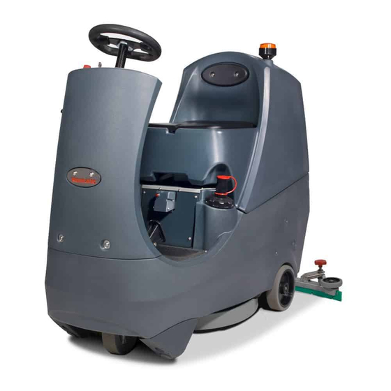
Page 3: Machine Overview
Machine Overview Operator control panel On-board charger and charge indicator Brush deck foot pedal Accelerator pedal Anti-tip buffers Pedestrian warning light Floor-tool raise / lower lever Floor-tool transit bracket Clean water tank fill point Air separator assembly Brush deck Waste water emptying hose 40 Amp battery fuse Vacuum hose Gel batteries... -
Page 4: Control Panel Overview
Control Panel Overview Water Flow Rate Indicator and Selection Button Brush Engage and Disengage Button Service Indicator Brush Pressure / Load Indicator Run Time Selection Button Battery Charge Level Indicator Off Aisle Vacuum Button On / Off Switch Forward / Reverse Switch LED Status Indicator Maximum Speed Control Horn Button... - Page 5 Charging Leads: Ho5VV-F x 1.0 mm x 3 Core No HOT drinks Transaxle 205190 when operating this Battery Charger (230V) machine. (115V) In the event of a breakdown contact your Numatic dealer or the Numatic Technical help line +44 (0)1460 269268...
- Page 6 MUST be removed. If this product does not have a factory installed Numatic battery charger and batteries then it is the responsibility of the owner and user of the product to ensure that the charging system and battery combination are compatible, fit for purpose and safe to use.
-
Page 7: Quick Set-Up Guide
Quick Set-Up Guide PLEASE READ BEFORE COMMENCING ANY OPERATION AFTER THE REMOVAL OF ALL THE PACKAGING, CAREFULLY OPEN AND CHECK THE CONTENTS. Contents: 1 x Operator Manual 2 x Battery Charger Lead 2 x Keys 1 x 40 Amp Fuse (1 x Spare) 1 x Maxi Fuse-puller Lift top tank assembly to reveal battery compartment. -
Page 8: Raise / Lower The Floor-Tool
Machine Set-Up Always ensure that the machine is switched off before making any adjustments Raise / Lower the Floor-tool To lower the floor-tool move the floor-tool lever into the upper position (Fig.7/9). To raise the floor-tool move the floor-tool lever into the lower position (Fig.8). Note: The machine will not operate in reverse with the Floor-tool lowered. -
Page 9: Raise / Lower The Brush Deck
Machine Set-Up Always ensure that the machine is switched off before making any adjustments Raise / Lower the Brush Deck To lower the brush deck slide the brush deck foot pedal forward with your foot (Fig.14) and gently release the foot pedal (Fig.15). -
Page 10: Filling The Clean-Water Tank
Machine Set-Up Always ensure that the machine is switched off before making any adjustments Filling the Clean-water Tank The CRO 8055 is equipped with a large capacity 80 litre clean water tank, allowing for large areas to be covered in a single fill. -
Page 11: Setting The Cleaning Controls
Machine Operation IMPORTANT Do not operate machine unless the operator manual has been read and fully understood. The machine is now ready to be driven to the cleaning site (see the quick set-up guide if necessary). Before performing the cleaning operation, place out appropriate warning signs and sweep or dust-mop the floor. When you have arrived at the cleaning site, lower the Floor-tool (see page 8) and the brush deck (see page 9). -
Page 12: Brush Pressure
Machine Operation Brush Pressure The machine is equipped with a brush-pressure load warning system (Fig.28). As the load on the Brush increases the LEDs on the Load Indicator will illuminate from left to right. Note: The run-time of the machine may decrease if the load on the brushes is increased Emergency Stop Button and Horn The CRO 8055 is equipped with an electronic braking system. -
Page 13: Maximum Speed Control
Machine Operation Machine in Use To operate, select forward, press the accelerator pedal. Vacuum pick-up and water-flow will turn on if selected and the brush and floor tool are in the lowered position, the machine will move forward. Clean water is dispersed evenly via ‘THRU- FEED’ scrubbing brushes. The waste water is then retrieved by the suction floor-tool (Fig.32). -
Page 14: Hose U-Bend Clip
Machine Operation Hose U-bend Clip The vacuum hose has a U-bend clip which creates a U-bend in the hose preventing water spillage when the vacuum is switched off. If you need to remove the U-bend clip for any reason always ensure it is refitted correctly before you resume operation (Fig 36-39). -
Page 15: Machine Cleaning
Machine Cleaning Always ensure that the machine is switched off prior to any maintenance. After use, empty waste-water tank using emptying hose and flush-out with clean water. Next remove floor-tool vacuum hose ensuring you remove the U-bend clip and flush out with clean water. Next empty clean water tank, using emptying hose and again flush out with clean water. - Page 16 Machine Cleaning Always ensure that the machine is switched off prior to any maintenance. Located in your waste water (top) tank is a vacuum shut off system, this prevents suction when the waste water tank is full. It also prevents foam created by high-foaming detergents from entering the motor. Sometimes the float vents get clogged and blocked, clean to ensure correct operation (Fig.46-47) reguarlly check and clean the air filter in the top of the assembly.
- Page 17 Changing the Floor-tool Blades Always ensure that the machine is switched off prior to any maintenance. To clean the floor-tool, lower the Floor-tool then unscrew the retaining knobs and slide off of the floor-tool holding bracket. Rinse the floor-tool assembly with clean water and refit. Periodically the floor-tool blades should be examined and checked for wear and damage.
-
Page 18: Floor-Tool Height Adjustment
Floor-tool Height Adjustment If your machine leaves streaks on the cleaned floor, either clean the floor-tool blade (See page 13) adjust blade pressure for optimum performance. -
Page 19: Machine Charging
Machine Charging Always ensure that the machine is switched off prior to charging. The battery charge indicator displays the charge level of the batteries; when fully charged, all meter lights are illuminated. As the machine is used and the batteries are discharged, the meter lights will go out from right to left. If the battery-charge level is allowed to discharge to the point that only three red lights are illuminated, the operator must consider charging the machine. -
Page 20: Free-Wheel Function
Free-wheel Function ALWAYS ENSURE THAT THE MACHINE IS ON LEVEL GROUND BEFORE DISENGAGING BRAKE ARM. NEVER DISENGAGE THE BRAKE WHEN THE MACHINE IS ON A SLOPE / GRADIENT. The CRO 8055 is equipped with a free-wheel function that will enable the operator to move the machine. The Free-wheel lever can be found on the right hand side of the rear axle (Fig.58). - Page 21 Battery Care Viewing Panel Charging Light Sequence Signal (LED) Meaning Red LED on First Phase (constant current Mode) Orange LED on Second Phase (Constant Voltage Mode) Green LED on Third Phase (Constant Voltage Mode) Charge Complete Cooling Fan Locked > 1 flash between pause Over Voltage Protection / Output Short Circuit / Battery Reverse Polarity >...
- Page 22 Contact Service Agent.
- Page 23 Contact Service Agent...
- Page 24 Trouble Shooting PROBLEM CAUSE SOLUTION Machine will not operate Missing or blown fuses Fit or replace fuse (page 7) Key in the ‘OFF’ position Turn key to ‘ON’ position (page 7) Low battery charge Charge batteries (page 19) Machine stop button in ‘OFF’ mode Reset stop button (page 12) Machine is connected and charging Take off charge (page 19)
- Page 25 Spare Parts BRUSHES: TOP TANK: 606028 207000 550 mm Polyscrub Brush Grit Filter Basket 606550 550 mm Nyloscrub Brush 208861 Air-Filter 900526 208980 500 mm Nuloc2 Drive Board Cro Foam Pad SQUEEGEE: 304503 Separator Seal Strip 1045 mm Long 599469 208862 Complete 650 mm Squeegee Assembly Seat Pad...
- Page 26 Schematic Diagram In the event of a breakdown contact your Numatic dealer or the Numatic Technical help line +44 (0)1460 269268 EU Declaration of Conformity EU DECLARATION CONFORMITY We hereby declare under our sole responsibility that the following equipment fulfi ls all the relevant provisions of the...
- Page 28 Distributed by Numatic International Limited Chard, Somerset TA20 2GB ENGLAND. Telephone 01460 68600 Fax: 01460 68458 www.numatic.co.uk Specification subject to change without prior notice 244488 11/15 (A05) www.numatic.co.uk © Numatic International Limited...
Need help?
Do you have a question about the CRO 8055/100T and is the answer not in the manual?
Questions and answers