Table of Contents
Advertisement
Style Selections
is a registered trademark
®
of LF, LLC. All rights reserved.
Questions, problems, missing parts? Before returning to your retailer, call our
customer service department at 1-877-888-8225, 8 a.m. - 8 p.m., EST, Monday - Friday.
EB15208
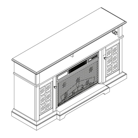
ELECTRIC FIREPLACE
WITH MEDIA MANTEL
MODEL #88287/26MM8715-Z248
1
ITEM #0667535
Français p. 21
Español p. 41
Lowes.com
Advertisement
Table of Contents

Related Manuals for Style selections 88287/26MM8715-Z248


Summary of Contents for Style selections 88287/26MM8715-Z248
- Page 1 Style Selections is a registered trademark ® of LF, LLC. All rights reserved. MODEL #88287/26MM8715-Z248 Français p. 21 Español p. 41 Questions, problems, missing parts? Before returning to your retailer, call our customer service department at 1-877-888-8225, 8 a.m. - 8 p.m., EST, Monday - Friday.
-
Page 2: Table Of Contents
TABLE OF CONTENTS Product Specifications ......................... 2 Safety Information ..........................3 Package Contents ..........................6 Hardware Contents..........................7 Preparation ............................8 Assembly Instructions........................... 8 Operating Instructions ........................16 Care and Maintenance ........................17 Troubleshooting ..........................18 Warranty ............................. 19 Replacement Parts List ........................20 PRODUCT SPECIFICATIONS VOLTAGE 120VAC, 60 Hz... -
Page 3: Safety Information
SAFETY INFORMATION Please read and understand this entire manual before attempting to assemble, operate or install the product. When using electrical appliances, basic precautions should always be followed to reduce the risk of fire, electrical shock and injury to persons, including the following: DANGER: •... - Page 4 4. The appliance is not to be used by children or persons with reduced physical, sensory or mental capabilities, or lack of experience and knowledge, unless they have been given supervision or instruction. SAFETY INFORMATION 5. Always unplug this appliance when not in use. 6.
-
Page 5: Save These Instructions
SAFETY INFORMATION • Batteries are to be inserted with the correct polarity. • Exhausted batteries are to be removed from the product. • Non-rechargeable batteries are not to be recharged. SAVE THESE INSTRUCTIONS Cold-climate installation: It is mandatory the outer walls be insulated to conform to applicable insulation codes. -
Page 6: Package Contents
PACKAGE CONTENTS PART DESCRIPTION QUANTITY Front Base Left Side Panel Right Side Panel Center Front Panel Left Door Right Door Mantel Top Wood Shelf Upper Side Panel Center Left Side Panel Center Right Side Panel Left Base Right Base Lower Insert Support Bar Center Shelf Support Panel Center Upper Back Panel... -
Page 7: Hardware Contents
HARDWARE CONTENTS (shown actual size) Screw Door Pull Wood Dowel Truss Head Screw Shelf Pin Qty: 8 (Not to scale) Qty: 10 Qty: 30 Qty: 16 Qty: 2 Long Screw Bolt Long Bolt Washer Door Bumper Qty: 6 Qty: 56 Qty: 6 Qty: 6 Qty: 4... -
Page 8: Preparation
PREPARATION Before beginning assembly of product, make sure all parts are present. Compare parts with package contents list and hardware contents list. If any part is missing or damaged, do not attempt to assemble, install or operate the product. To protect the product from possible scratches, please assemble the parts on a scratch-free surface. - Page 9 3. Insert plastic blocks from 3-block connector pack (V) into lower insert support bar (N), securing with bolts (GG). Then, align left base (L) and right base (M) to front base (A), and slide lower insert support bar (N) where shown, securing with bolts (GG).
- Page 10 5. Attach support panel (P) where shown to mantel top (G) using bolt (GG). Hardware Used Bolt 6. Insert wood dowels (AA) into assembly where shown, then attach center shelf (O). Secure from underneath using bolts (GG) and from above using long screws (FF).
- Page 11 8. Insert plastic blocks from 2-block connector pack (U) where shown into center front panel (D). Secure with bolts (GG). Insert wood dowels (AA) into each end of center front panel (D), then attach center front panel (D) to center left side panel (J) and center right side panel (K).
- Page 12 10. Insert wood dowels where shown into assembly, then attach base assembly from Step 3 to unit. Secure where shown with long screws (FF). Hardware Used Wood Dowel Long Screw Bolt 11. Set the assembly upright. Attach the center upper back panel (Q) and rear panels (R) to the back of the assembly using truss head screws (BB).
- Page 13 13. Remove the preassembled bolts from the door pulls (DD), then install door pulls (DD) to left door (E) and right door (F) with the bolts. Hardware Used Door Pull 14. Attach left door (E) and right door (F) to assembly using screws preassembled to the hinges.
- Page 14 16. Align insert support bar (S) with the holes on center right side panel (K) and center left side panel (J). Attach plastic blocks from 2-block connector pack (U) where shown to secure insert support bar (S). Secure with bolts (GG). Hardware Used Bolt 17.
- Page 15 19. WARNING: Installing the tipping restraint hardware will help prevent accidents and/or damage to the unit. It is highly recommended you complete this step. Unit Anchor To secure the item to the wall, find and mark a stud wall closest to the edge of the left side of the mantel. Attach the wall anchor from the tipping restraint hardware pack (T) at the marked locations using 2 of the screws from the pack.
-
Page 16: Operating Instructions
OPERATING INSTRUCTIONS The heater can be operated by either the remote control or the control panel. Control Panel Display Front View of Insert (Y) Remote (X) FUNCTION ICON DESCRIPTION POWER Use the POWER button to turn on or off the fireplace from the remote or control panel. -
Page 17: Care And Maintenance
CARE AND MAINTENANCE • Dust the fireplace regularly with a soft, non-lint producing cloth or household dusting product. • Clean the fireplace with a gentle non-abrasive household cleaner. Make sure to dry the fireplace immediately with a soft cloth or towel. •... -
Page 18: Troubleshooting
TROUBLESHOOTING PROBLEM POSSIBLE CAUSE CORRECTIVE ACTION Unplug the fireplace, remove the back panel of the fireplace and The thermostat sensor is check that the thermostat is plugged into the main circuit board. If Display shows “ ”. broken or disconnected. this does not solve the problem, contact customer service for a replacement thermostat sensor. -
Page 19: Warranty
1-YEAR LIMITED WARRANTY The manufacturer warrants this product to be free from manufacturing and material defects for a period of one year from date of purchase, subject to the following conditions and limitations. 1. Install and operate this item in accordance with the installation and operating instructions furnished with the product at all times. -
Page 20: Replacement Parts List
Y15-C70-P85 Emberbed with Log Y15-S148-P02 Emberbed Circuit Board Y15-C75-P44E Blue Flame Circuit Board Y15-C70-P40BL Flame Circuit Board Y15-C76-P40 Spinner Y15-S148-P11 Remote Control P115 Printed in China Style Selections is a registered trademark ® of LF, LLC. All rights reserved. Lowes.com...
Need help?
Do you have a question about the 88287/26MM8715-Z248 and is the answer not in the manual?
Questions and answers
I keep getting an E3 code on my insert which is overheating, ehat is overheating.
The E3 code indicates that the manual reset overheat protection has triggered. To resolve this, inspect the heater to ensure that air inlets and outlets are not blocked, as this may cause overheating. Unplug the heater for 30 minutes to allow it to cool down, then replug and operate it while monitoring for signs of overheating. If the problem persists, discontinue use and contact customer service.
This answer is automatically generated
Continuous E3 message. Vacuming vent usually resolve problem not this time. Plug in plug not working. Tried everything in manual. Is there a way to isolate problem. E3 shows up with every option.