Table of Contents
Advertisement
WARNING: This appliance
is equipped for (Natural and
Propane) gas. Field conversion is
not permitted other than between
natural or propane gases.
WARNING: IF THE INFORMATION IN THIS MANUAL IS NOT FOLLOWED
EXACTLY, A FIRE MAY RESULT CAUSING PROPERTY DAMAGE, PERSONAL
INJURY, OR LOSS OF LIFE.
– Do not store or use gasoline or other flammable vapors and liquids in vicinity of this or any
other appliance.
•
Do not try to light any appliance.
•
Do not touch any electrical switch; do not use any phone in your building.
•
Immediately call your gas supplier from a neighbor's phone. Follow the gas
supplier's instructions.
•
If you cannot reach your gas supplier, call the fire department.
– Installation and service must be performed by a qualified installer, service agency
or the gas supplier.
This is an unvented gas-fired heater. It uses air (oxygen) from the room in which it is
installed. Provisions for adequate combustion and ventilation air must be provided.
Refer to Air For Combustion and Ventilation section on page 8 of this manual.
INSTALLER : DO NOT DISCARD THIS MANUAL - LEAVE FOR HOMEOWNER'S
FUTURE REFERENCE.
This appliance may be installed in an aftermarket, permanently located manufactured
(mobile) home, where not prohibited by local codes. This appliance is for use with the
type of gas indicated on the rating plate only. This appliance is not convertible for use
with other gases.
Questions, problems, missing parts? Before returning to your retailer, contact
our customer service department at 1-866-573-0674, 8:00 a.m - 4:30 p.m.,
EST, Monday - Friday or e-mail customerservice@usaprocom.com.
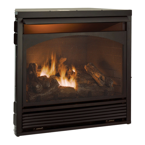
VENT-FREE GAS FIREPLACE INSERT
CAUTION - FOR YOUR SAFETY
ITEM #0293807
MODEL #SSFBD32RT
Español p. 37
LS-SSFBD32RT-1002
Advertisement
Table of Contents

Related Manuals for Style selections SSFBD32RT


Summary of Contents for Style selections SSFBD32RT
- Page 1 ITEM #0293807 VENT-FREE GAS FIREPLACE INSERT MODEL #SSFBD32RT Español p. 37 WARNING: This appliance is equipped for (Natural and Propane) gas. Field conversion is not permitted other than between natural or propane gases. CAUTION - FOR YOUR SAFETY WARNING: IF THE INFORMATION IN THIS MANUAL IS NOT FOLLOWED EXACTLY, A FIRE MAY RESULT CAUSING PROPERTY DAMAGE, PERSONAL INJURY, OR LOSS OF LIFE.
-
Page 2: Table Of Contents
TABLE OF CONTENTS Safety Information...........................3 Product Features..........................6 Air For Combustion and Ventilation....................8 Installation .............................11 Installing Logs..........................20 Operation............................22 Care and Maintenance........................28 Troubleshooting..........................30 Replacement Parts........................33 WARNING: Read the installation & operation instructions before using this appliance. IMPORTANT: Read instructions and warnings carefully before starting installation. Failure to follow these instructions may result in a possible fire hazard and will void the warranty. -
Page 3: Safety Information
SAFETY INFORMATION IMPORTANT: Read this owner’s manual carefully and completely before trying to assemble, operate, or service this heater. Improper use of this heater can cause serious injury or death from burns, fire, explosion, electrical shock, and carbon monoxide poisoning. Only a qualified installer, service agent, or local gas supplier may install and service this product. - Page 4 Do not place Propane/LP supply tank(s) inside any structure. Propane/LP supply tank(s) must be placed outdoors. This heater needs fresh air ventilation to run properly. This heater has an Oxygen Depletion Sensing (ODS) safety shut-off system. The ODS shuts down the heater if not enough fresh air is available.
- Page 5 Do not add extra logs or ornaments such as pine cones, vermiculite, or rock wool. Using these added items can cause sooting. Do not add lava rock around base. Rock and debris could fall into the control area of heater. After servicing, always replace screen before operating heater.
-
Page 6: Product Features
PRODUCT FEATURES SAFETY PILOT This heater has a pilot with an Oxygen Depletion Sensing (ODS) safety shutoff system. The ODS/pilot shuts off the heater if there is not enough fresh air. PIEZO IGNITION SYSTEM This heater is equipped with an electronic piezo control system. This system requires AAA batteries (provided). - Page 7 UNPACKING 1. Remove top inner pack. 2. Tilt carton so that heater is upright. 3. Remove protective side packaging. 4. Slide heater out of carton. 5. Remove protective plastic wrap. 6. Hold the screen, lift, and pull forward. 7. Remove log set by cutting plastic ties. 8.
-
Page 8: Air For Combustion And Ventilation
AIR FOR COMBUSTION AND VENTILATION WARNING: This heater should not be installed in a confined space or unusually tight construction unless provisions are provided for adequate combustion and ventilation air. Read the following instructions to ensure proper fresh air for this and other fuel burning appliances in your home. - Page 9 DETERMINING FRESH-AIR FLOW FOR HEATER LOCATION Determining if You Have a Confined or Unconfined Space Use this worksheet to determine if you have a confined or unconfined space. Space: Includes the room in which you will install heater plus any adjoining rooms with door-less passageways or ventilation grills between the rooms.
- Page 10 WARNING: If the area in which the heater may be operated is smaller than that defined as an unconfined space or if the building is of unusually tight construction, provide adequate combustion and ventilation air by one of the methods described in the National Fuel Gas Code, ANS Z223.1, Section 5.3 or applicable local codes.
-
Page 11: Installation
INSTALLATION NOTICE: This heater is intended for use as supplemental heat. Use this heater along with your primary heating system. Do not install this heater as your primary heat source. If you have a central heating system, you may run system’s circulating blower while using heater. - Page 12 NOTE: When heater is installed directly on carpeting, tile or other combustible material, other than wood flooring, the heater must be installed on a metal or wood panel extending the full width and depth of the heater. BUILT-IN FIREPLACE INSTALLATION Clearance to Combustibles Fig.
- Page 13 IMPORTANT: When finishing your firebox, Rough Opening for Installing in Corner Fig. 8 - combustible materials such as wall board, gypsum board, sheet rock, drywall, plywood, etc, must have ½ -in. clearance to the sides and top of the firebox. Combustible materials should never overlap the firebox front.
- Page 14 CONNECTING TO GAS SUPPLY WARNING: A qualified technician must connect heater to gas supply. Follow all local codes. WARNING: This appliance requires a 3/8 in. NPT inlet connection to pressure regulator (see Fig. 10). CAUTION: Never connect heater directly to the gas supply. This heater requires an external regulator (not supplied).
- Page 15 CAUTION: Use only new black iron or steel pipe. Internally tinned copper tubing may be used in certain areas. Check your local codes. Use pipe of ½ in. diameter or greater to allow proper volume gas to heater. If pipe is too small, loss of pressure will occur.
- Page 16 CAUTION: Two gas line installations at the same time is forbidden. Do not open the cover while the machine is running. Heater is pre-set at factory for propane gas; no changes are required for connecting to propane. Only a qualified installer or service technician can perform gas selection and connecting to gas supply.
- Page 17 Fig. 13 NATURAL GAS PROPANE GAS Fig. 14 NATURAL GAS PROPANE GAS PLUG Fig. 15 PLUG NATURAL GAS PROPANE GAS...
- Page 18 CHECKING GAS CONNECTIONS WARNING: Test all gas piping and connections for leaks after installing or servicing. Correct all leaks immediately. WARNING: Never use an open flame to check for a leak. Apply a mixture of liquid soap and water to all joints. If bubbles form, there may be a leak. Correct all leaks immediately. Pressure Testing Gas Supply Piping System Test Pressures In Excess Of 1/2 PSIG ( 3.5kPa ) 1.
- Page 19 Installation for Decorative Trim: 1. Installation for Left/Right Decorative Trim: Wedge two flanged screws on sides of the shell into slots of Left/Right Decorative Trim. (See Fig. 18) 2. Installation for Top Decorative Trim: Wedge two flanged screws on top cover into slots of Top Decorative Trim. (See Fig.
-
Page 20: Installing Logs
INSTALLING LOGS Fig. 22 - Installing Log Set WARNING: Failure to position the parts Log Set Burner Ports in accordance with these diagrams or failure to use only parts specifically approved with this heater may result in property damage or personal injury. CAUTION: After installation, and periodically thereafter, check to ensure that no flame comes in contact with any log. - Page 21 STEP 7: Insert the pinhole on the upper part of STEP 6: Install the log 6 on the right front angle. log 7 in the pin on log 1, log 3 and log 5. STEP 9: Insert the pinhole on the upper part of STEP 8: Insert the pinhole on the upper part of log 8 log 9 in the pin on log 4 and log 6.
-
Page 22: Operation
OPERATION FOR YOUR SAFETY READ BEFORE LIGHTING WARNING: If you do not follow these instructions exactly, a fire or explosion may result causing property damage, personal injury, or loss of life. NOTICE: During initial operation of new heater, burning logs will give off a paper burning smell. - Page 23 LIGHTING INSTRUCTIONS 1. STOP! Read the safety information on the front and back of the warning plate on page 22. 2. Make sure manual shutoff valve is fully open. 3. Unscrew ignitor cap and install an AAA type battery with the anode (+) pointing out. Replace cap.
- Page 24 REMOTE CONTROL OPERATION Fig. 24 REMOTE CONTROL OPERATION This appliance must not be used with glass doors in the closed position. This can lead to pilot outages and severe sooting outside the fireplace. The transmitter operates on two AAA batteries. KEY SETINGS ON - Operates unit to on position, Manually operated solenoid ON.
- Page 25 Fig. 29 After 3 seconds the LCD screen will default to display room temperature and the word TEMP will show (Fig. 29). (Flame icon will appear on LCD screen in manual on mode). OFF OPERATION Press the OFF key and the appliance flame will Fig.
- Page 26 REMOTE CONTROL OPERATION NOTES: The Thermo Feature on the transmitter operates the appliance whenever the ROOM TEMPERATURE varies a certain number of degrees from the SET TEMPERATURE. This variation is called the “SWING” or TEMPERATURE DIFFERENTIAL. The normal operating cycle of an appliance may be -4 times per hour depending on how well the room or home is insulated from the cold or drafts.
- Page 27 INSPECTING BURNERS Check pilot flame pattern and burner flame patterns often. PILOT FLAME PATTERN 1. Turn control knob to pilot position. 2. Inspect pilot flame and refer to Fig. 34 and 35. • Fig. 34 shows a correct pilot flame pattern. •...
-
Page 28: Care And Maintenance
CARE AND MAINTENANCE WARNING: Failure to keep primary air openings of burners clean may result in sooting and property damage. CAUTION: You must keep control areas, burner, and circulating air passageways of heater clean. Inspect these areas of heater before each use. Have heater inspected yearly by a qualified service person. - Page 29 CLEANING ODS/PILOT Use a vacuum cleaner, pressurized air, or a small, soft bristled brush to clean. A yellow tip on the pilot flame indicates dust and dirt in the pilot assembly. There is a small pilot air inlet hole about two inches from where the pilot flame comes out of the pilot assembly (see Fig.
-
Page 30: Troubleshooting
TROUBLESHOOTING WARNING: If you smell gas: • Shut off gas supply. • Do not try to light any appliance. • Do not touch any electrical switch; do not use any phone in your building. • Immediately call your gas supplier from a neighbor’s phone. Follow the gas supplier’s instructions. - Page 31 Problem Possible Cause Corrective Action ODS/pilot lights but flame 1. Control knob is not fully 1. Press in control knob fully. goes out when control knob pressed in. is released. 2. Control knob is not pressed 2. After ODS/pilot lights, keep in long enough.
- Page 32 Problem Possible Cause Corrective Action Slight smoke or odor 1. Residues from 1. Problem will stop after a during initial operation. Manufacturing process. few hours of operation. Heater produces a 1. Turning control knob to high 1. Turn control knob to low (1) whistling noise when (5) position when burner is position and let warm up for...
-
Page 33: Replacement Parts
REPLACEMENT PARTS NOTE: Use only original replacement parts. This will protect your warranty coverage for parts replaced under warranty. PARTS UNDER WARRANTY Call Customer Service toll free at (1-866-573-0674) for referral information. When calling Customer Service, have ready: • Your name •... - Page 34 REPLACEMENT PARTS LIST For replacement parts, call our customer service department at 1-866-573-0674, 8:00 a.m - 4:30 p.m., EST, Monday - Friday or e-mail customerservice@usaprocom.com. Part.. Description Part # NDD0308x400 Hood FB32D201 DF Regulator RV83FI-4/9 Logs Assembly FB32D500 Log 1 FB32D501B Log 2 FB32D502B...
- Page 36 2-YEAR LIMITED WARRANTY The manufacturer warrants this product to be free from defects in workmanship and material present at time of shipment from the factory for two (2) years from the date of purchase. This warranty applies only to the original purchaser. The manufacturer agrees to correct such defect at no charge or, at our option, replace the product with a comparable or superior model.
Need help?
Do you have a question about the SSFBD32RT and is the answer not in the manual?
Questions and answers