Table of Contents
Advertisement
Advertisement
Table of Contents

Related Manuals for Zoom 5354


Summary of Contents for Zoom 5354
- Page 1 Cable Modem/Router with Wireless-N U S E R M A N U A L...
- Page 2 Do not place the cable modem in a confined space that may cause overheating. Do not restrict the flow of air around the cable modem. Zoom Telephonics assumes no liability for damage caused by any improper use of the cable modem. ...
-
Page 3: Table Of Contents
CHAPTER 5 - USING AN EXTERNAL USB DRIVE Installing a USB Drive............................32 Sharing your USB Drive’s Data with Devices on your Network ..............36 CHAPTER 6 - ONLINE GAMING Gaming .................................39 DMZ Host..............................40 Port Triggers..............................41 CHAPTER 7 - ADVANCED SETTINGS Changing Default Settings..........................44 Accessing the Zoom Configuration Manager ....................45 Understanding the Configuration Manager Interface Screens..............46 Configuration Manager Interface Menus ..................... 47 CHAPTER 8 - STATUS MENU OPTIONS Software ...............................49 Connection ..............................50 Security.................................51 ... - Page 4 Diagnostics ..............................53 Event Log ..............................56 CHAPTER 9 - BASIC MENU OPTIONS Setup ................................57 DHCP................................60 DHCPv6.................................61 LAN IPv6 ...............................62 DDNS ................................63 Backup/Restore ............................65 CHAPTER 10 - ADVANCED MENU OPTIONS Options .................................67 IP Filtering ..............................70 MAC Filtering..............................71 Port Filtering..............................73 Forwarding..............................74 Port Triggers..............................76 DMZ Host..............................78 RIP Setup ..............................79 CHAPTER 11 - FIREWALL MENU OPTIONS Basic................................82 Event Log ..............................83 CHAPTER 12 - PARENTAL CONTROL MENU OPTIONS...
- Page 5 APPENDIX B: IF YOU NEED HELP APPENDIX C: COMPLIANCE ...
-
Page 6: Chapter 1 - Getting Started
Getting Started This User Manual provides instructions for connecting and configuring your Cable Modem/Router and for setting up wireless and wired connections to the cable modem. One chapter shows how to connect a USB Flash drive or hard drive for Network Addressable Storage and media streaming. - Page 7 To learn how to change your default password, please see Accessing the Zoom Configuration Manager. If you want to plug a USB drive into either USB port of the Cable Modem/Router...
-
Page 8: Chapter 2 - Installing The Cable Modem/Router With Wireless-N
Installing the Cable Modem/Router with Wireless-N This chapter provides basic instructions for connecting the hardware and configuring the Cable Modem/Router with Wireless-N using the Zoom Configuration Manager. This chapter is almost identical to the printed Quick Start. We strongly recommend that you use the cable modem stand to make the cable modem stand vertically. -
Page 9: If You Are Replacing An "Old" Cable Modem, Do This
CM-MAC address. You may also be asked for your cable modem's model name and number, which is ZOOM 5354. If you need the modem's serial number, you can find it near the MAC address on the label. Comcast only allows a 12 digit serial number so if they ask for it;... -
Page 10: If This Is A First-Time Cable Modem Installation (That Is, You Are Not Replacing An "Old" Cable Modem), Do This
If the coaxial cable has a screw-on connector, turn the connector clockwise when tightening the cable onto the Zoom cable modem.. (If you’re not sure a cable is live, you can see whether you get a good TV signal when that cable is used with a working TV set-top box.) Here are some ways... - Page 11 Cable Modem/Router for details on establishing a wireless connection. Connect the Zoom power cube between the Zoom cable modem and a live power jack. Make sure the cable modem’s Power Switch is ON. It normally takes 5 to 30 minutes to establish an Internet link the first time a Cable Modem/Router connects to a cable service provider.
- Page 12 If no web page appears after opening your browser, you need to call your cable company to register your modem. Below is a list of some major cable service providers’ phone numbers to call to activate your cable modem. Note that this list is subject to change.
-
Page 13: Hardware Connection
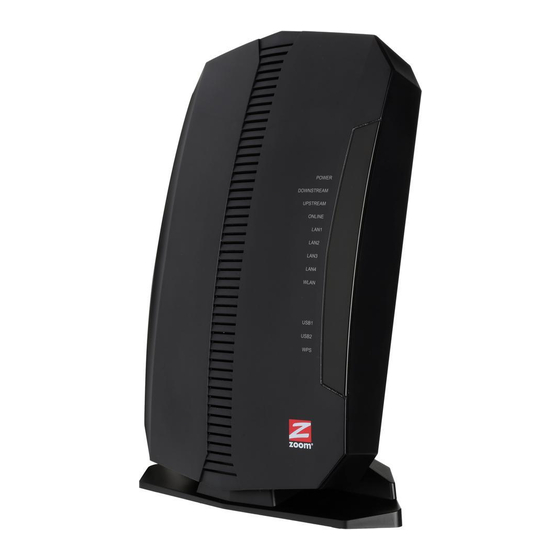
To learn how to change your default password, please see Accessing the Zoom Configuration Manager. If you want to use the Cable Modem/Router to stream media from a USB drive or... - Page 14 (Gigabit Ethernet 1-4) port. Cable Connect your coaxial cable line to this port. Front Panel LEDs Your Zoom cable modem has several lights on its front panel to help you monitor the Cable Modem/Router’s status. LIGHT COLOR DESCRIPTION Power is supplied to the cable...
- Page 15 Blinking: Data is flowing and Ethernet is connected LAN 1-4 Connected at highest LAN speed, 1 Green or Green: Ethernet LAN Gbps Amber ports Connected at 10 or 100 Mbps Amber: No Ethernet link detected OFF: Blinking: Data is flowing WLAN Green Wireless in enabled...
- Page 16 Connecting Other Devices to the Cable Modem/Router This chapter explains how to connect devices (computers, phones, tablets, game stations, etc.) to the Cable Modem/Router. These devices can be connected either wirelessly or to one of the Ethernet ports on your Cable Modem/Router. If you are connecting a computer or other device to an Ethernet LAN port of the Cable Modem/Router, please go to Connecting Additional Computers and/or Other Devices to...
-
Page 17: Establishing Your Wireless Network
The default SSID (wireless network name) is assigned as Zoomxxxx (where xxxx ar 4 random alpha-numeric characters). This SSID is printed on the back label of your Cable Modem/Router. Most users should simply use these default settings. If you want to change these default settings please see, Chapter 4, Changing the Default Wireless Settings before... -
Page 18: Connecting A Wireless-Enabled Device (Including The Iphone Or Other Cellular Phones, Ipad Or Other Tablets, The Ipod Touch, Etc.) To The Cable Modem/Router
Some computers may need a wireless network adapter installed. This can be a USB adapter, PC Card adapter, or PCI adapter. When you install the adapter, make sure that it is set to infrastructure or access point mode (NOT ad-hoc or peer-to-peer mode). If you need help installing your wireless adapter or setting its mode, refer to the documentation that came with it. -
Page 19: Connecting A Windows 8.1 Or 8 Computer With Built-In Wireless Capabilities
Connecting a Windows 8.1 or 8 Computer with Built-in Wireless Capabilities 1 Click the Wireless Network Configuration utility icon in your computer’s system tray. 2 Typically you then click Zoomxxxx where xxxx is 4 random alpha-numeric characters. Zoomxxxx is the SSID printed on the bottom label of your Cable Modem/Router. -
Page 20: Connecting A Windows 7 Computer With Built-In Wireless Capabilities
Connecting a Windows 7 Computer with Built-in Wireless Capabilities 1 Click the Wireless Network Configuration utility icon in your computer’s system tray. 2 Typically you then click Zoomxxxx where xxxx is 4 random alpha-numeric characters. Zoomxxxx is the SSID printed on the bottom label of your Cable Modem/Router. - Page 21 3 Click Connect. If you want to connect to this network automatically in the future, check the Connect Automatically checkbox. 4 When prompted to enter your Network Security Key, enter your Pre-Shared Key (Security Key/Password) and hit Connect. Your Security Key/Password can be found on the bottom label of your Cable Modem/Router.
-
Page 22: Connecting A Windows Xp Computer With Built-In Wireless Capabilities
Connecting a Windows XP Computer with Built-in Wireless Capabilities 1 On your Windows desktop, click the Wireless Network Icon in the System Tray. 2 Typically you then click Zoomxxxx where xxxx is 4 random alpha-numeric characters. Zoomxxxx is the SSID printed on the bottom label of your Cable Modem/Router. -
Page 23: Connecting A Macintosh Os X Computer With Built-In Wireless Capabilities
Connecting a Macintosh OS X Computer with Built-in Wireless Capabilities 1 Click the Wi-Fi icon in the menu bar. If the Wi-Fi icon does not appear on your menu bar, please refer to your built-in Macintosh documentation for how to enable wireless. Note: On versions prior to OS 10.7 the Wi-Fi icon is called AirPort. -
Page 24: Connecting A Computer With A Wireless Adapter To The Cable Modem/Router
Connecting a Computer with a Wireless adapter to the Cable Modem/Router 1 Go to the computer that is set up with a wireless adapter that you want to add to the network. For many wireless adapters, you will use their configuration manager software and click a Scan button or select a Site Scan, Scan Networks, or other similarly named tab to do a site search. -
Page 25: Using Wps As An Alternative Way To Set Up Your Wireless Network
Using WPS as an alternative way to set up your Wireless Network If all the Wi-Fi compatible wireless devices on your network support WPS, you can choose to quickly setup your wireless network by pushing a button on your cable modem/router and on each wireless device connecting to your cable modem/router. -
Page 26: Connecting Additional Computers And/Or Other Devices To The Cable Modem/Router's Ethernet/Lan Ports
5 Press the Wi‑Fi Protected Setup (WPS) button on the router for at least 3 seconds. (You do not need to type a security key or passphrase in the Security key text box on your Windows machine). The Cable Modem/Router will automatically set up the computer to connect to the network and apply the network's security settings. - Page 27 1 If you connected the Cable Modem/Router to a computer using a wired connection when setting up the Cable Modem/Router, unplug the computer now if you don’t want that computer to stay connected to the Cable Modem/Router. 2 To connect a computer or other Ethernet-capable device, plug one end of an Ethernet cable into an available Ethernet (LAN 1, 2, 3, or 4) port on the Cable Modem/Router and plug the other end of the Ethernet cable into the Ethernet port of the additional device you want to connect to the Cable Modem/Router.
-
Page 28: Chapter 4 - Changing The Default Wireless Settings
Changing the Default Wireless Settings Your Cable Modem/Router comes from the factory with a default SSID (Wireless Network Name), WPA-PSK/WPA2-PSK wireless security and a random Wireless Security Key (Wireless Password). These default settings for your router are listed on the bottom label of your unit. -
Page 29: Changing Your Wireless Network Name(Ssid) And Pre-Shared Key
Disabling Security Changing your Wireless Network Name(SSID) and Pre-Shared 1 Open the Zoom Configuration Manager by typing the following in your Web browser's address bar: http://192.168.0.1 2 In the Login dialog box, type the following User Name and Password in lower case, then click Login. -
Page 30: Setting Up Security Using Wep
WPA2. WEP can be configured two ways: 64-bit and 128-bit. 128-bit WEP provides more security than 64-bit. 1 Open the Zoom Configuration Manager by typing the following in your Web browser's address bar: http://192.168.0.1 2 In the Login dialog box, type the following User Name and Password in lower case, then click Login. -
Page 31: Disabling Security
Cable Modem/Router. Follow the instructions below. 1 Open the Zoom Configuration Manager by typing the following in your Web browser's address bar: http://192.168.0.1 2 In the Login dialog box, type the following User Name and Password in lower case, then click Login. -
Page 32: Chapter 5 - Using An External Usb Drive
Using an External USB Drive You may want to use one or both of the USB ports for attaching a USB drive. You can attach most USB drives, including a USB flash drive or an external USB hard drive, to either USB port on your Cable Modem/Router. - Page 33 The default name of the DLNA/UPnP server is Zoom-DMS. Your device may not support all the media file types that are supported by the Cable Modem/Router. If a file type is not supported by your device, it will not show up in your device’s menu.
- Page 34 In the left hand window click on Network. All the devices connected to your network should appear in the right side window. Under Media Devices, right click on Zoom-DMS and select Open Media Player. The files on the media server will be listed under Other Libraries.
- Page 35 Scroll over until you see the Media Player app. Select the Media Player app to launch it. Now select Zoom-DMS as the device you would like to stream your media from. Select Video to view videos, Pictures to view your pictures, or Music to listen to music from the Cable Modem/Router.
-
Page 36: Sharing Your Usb Drive's Data With Devices On Your Network
Your Cable Modem/Router lets you share the data on your USB drive with the devices on your network. The default name of the Cable Modem/Router is Zoom-LVG. When searching your network select Zoom-LVG to access the drives attached to your Cable Modem/Router. - Page 37 On the Dock bar click on the Finder icon. If Zoom-LVG is not shown in the left hand pane you will need to connect to the USB drive, to do this continue on to step 3. If Zoom-LVG appears in the left hand menu, click on it and you will now be able to access your data.
- Page 38 several other apps you can choose, both free and paid. Please download the app you select and follow the setup directions to access your data. ...
-
Page 39: Chapter 6 - Online Gaming
Online Gaming Read this chapter if you are going to use your Cable Modem/Router for online gaming. Some online games require you to make changes to your firewall. This chapter explains the different ways you can modify the firewall to allow your online gaming system access. Gaming If you are using your router for gaming, you may need to make changes to the router’s firewall setting for the game to work. -
Page 40: Dmz Host
DMZ Host The DMZ (De-militarized Zone) Host page allows you to configure a network device (e.g. a PC or gaming system) to be visible directly to the Internet. This may be used if a game doesn’t work with port triggers or if you are using a gaming system, where security is less of a concern. -
Page 41: Port Triggers
Enter the last byte of the LAN IP address of the static IP address you assigned to your gaming system. For example if you assigned 192.168.0.5 enter 5. Click Apply. Your gaming system should now work with all your online games. Port Triggers Port Triggering works by sensing when your game sends data out through a specific port. - Page 42 use the same ports as both the triggering port and the target port as shown below. To setup port triggering for World of Warcraft: Launch a Web browser. In the browser address bar, type http://192.168.0.1 and press the Enter key. In the Login screen, enter: default username: admin default password: admin...
- Page 43 Select TCP in the Protocol drop down menu since these ports use TCP. Enter a name for this rule, for example WOW1. Click Enable then click Apply. Your new rule will appear in the table. Repeat steps 7-9 for the next rule. In this case only one port is used, 3724. Enter 3724 in the Trigger Start/End Port and Target Start/End Port fields.
-
Page 44: Chapter 7 - Advanced Settings
Cable Modem/Router is installed are sufficient. However, those who want or need to change the default settings can do so using the advanced setup pages in the Zoom Configuration Manager. This chapter includes: ... -
Page 45: Accessing The Zoom Configuration Manager
Cable Modem/Router and its ports. To access the Zoom Configuration Manager, use the following procedure: Launch a Web browser. Note: Your computer does not have to be online to configure your Cable Modem/Router. -
Page 46: Understanding The Configuration Manager Interface Screens
Click the Login button to access the Cable Modem/Router. The Status page appears, showing connection status information about your Cable Modem/Router After you log in to the Zoom Configuration Manager interface, we strongly recommend that you change the default password as follows: On the left hand menu click on Security. -
Page 47: Configuration Manager Interface Menus
Figure 2. Main Areas on the Configuration Manager Interface Every menu has submenus associated with it. If you click a menu item, the submenus appear on the left frame of the Configuration Manager. For example, if you click the Status menu item, the submenu Software, Connection, Security, Diagnostics, and Event Log appear on the left column (see Figure 3). - Page 48 sections of this User Manual based on your intended use of the Cable Modem/Router with Wireless-N. Each of the menu options in your Configuration Manager is covered as a separate chapter in the remaining portion of the User Manual. Refer to the chart on the next page to go to a specific menu option.
-
Page 49: Chapter 8 - Status Menu Options
Status Menu Options The Status Menu lets you: View the status and connection information of the Cable Modem/Router Change the administrator password Use diagnostic tools for troubleshooting Software The Software page is a read-only screen that shows the Cable Modem/Router’s current system software version. -
Page 50: Connection
Figure 4. Software Menu Table 2. Software Menu Option Option Description Information Shows the information on the current system software. Shows the system up time, network accessibility, and IP address of Status the Cable Modem/Router. Connection The Connection page is a read-only screen that shows the status of steps in your Cable Modem/Router registration process. -
Page 51: Security
Figure 5. Example of Connection Page By default the router is configured to use Dual mode (or Dual Stack mode). Most users should use this setting. However your provider may ask you to change the eRouter Provisioning mode to eRoute_IPv4only mode or eRoute_IPv6only mode. Security The Security page allows you to configure access privileges, reboot and restore the Cable Modem/Router to its factory defaults. - Page 52 submenu. Figure 6 shows an example of the menu and Table 3 describes the items you can select. Figure 6. Example of Security Page How to change the default password used to access your device: Enter admin in the User Name dialog box. The default user name can not be changed.
-
Page 53: Diagnostics
Table 3. Security Menu Option Option Description User Name Enter the User Name for the administrator. Enter the existing security password. The password can be Current Password found on the bottom label of the unit. Enter the new security password. New Password Re-Enter New Re-enter (confirm) the new security password. - Page 54 Table 4 describes the items you can select. Figure 7. Example of Diagnostics - Ping Page ...
- Page 55 Figure 8. Example of Diagnostics - Traceroute Page To run either utility: Select the utility from the Utility drop-down list. Make any changes to the default parameters. Select Start Test to begin. The window will automatically be refreshed as the results are displayed in the Results table.
-
Page 56: Event Log
Table 4. Diagnostics Menu Option Option Description Utility Select the utility for troubleshooting. Parameters Enter the required parameters to perform diagnostics. Click this button to begin diagnostic after making any changes to the Start Test default parameters. Abort Test Click this button to abort Ping diagnostics. Clear Results Click this button to clear the results table. -
Page 57: Chapter 9 - Basic Menu Options
Basic Menu Options The Basic Menu lets you: Configure the basic settings of your Cable Modem/Router Configure DHCP server for the LAN Configure DDNS service Backup and restore of configuration settings Setup The Setup page allows you to configure the basic features of the Cable Modem/Router related to your ISP’s connection. - Page 58 Figure 10. Example of Setup Page Table 5. Setup Menu Option Option Description LAN IPv6 LAN IPv6 address will appear here when connected to IPv6 service. Address LAN IPv4 Set the base LAN IP for your private network. By default this is Address 192.168.0.1 There is normally no need to change this.
- Page 59 Connection options are via DHCP or manual configuration of a static IP address. Unless you have arranged for a static IP address from your service Type provider, you should leave this setting at its default, DHCP. By default is set to 0 which uses the default setting. Allows you to IPv4 MTU Size select between 600 to 1500.
-
Page 60: Dhcp
DHCP The DHCP page allows you to configure your Cable Modem/Router’s DHCP server. To access the DHCP page: Click Basic in the menu bar. Then click the DHCP submenu. Figure 11 shows an example of the menu and Table 6 describes the items you can select. -
Page 61: Dhcpv6
Select Yes to use internal DHCP server of the Cable Modem/Router, DHCP Server or select No to disable it. Starting Local Configure the starting IP address for IP leases available to devices Address on the LAN. Number of Configure the number of PCs supported on the LAN. CPEs Configure the time a lease will last before it must be renewed. -
Page 62: Lan Ipv6
Table 7 DHCPv6 Menu Option Option Description System Enter the prefix for you IPv6 LAN network. For example enter Delegated Prefix FE80::1 if you want to use a Link Local address User Defined Check to enable System Delegated Prefix. Prefix If using System Delegate Prefixes the LAN Delegated Prefix will LAN Delegated be automatically configured, otherwise enter your LAN delegated... -
Page 63: Ddns
Figure 13. Example of LAN IPv6 Page Table 8 LAN IPv6 Option Option Description IP Address The IP address of devices on your network MAC Address The MAC address of the device. Reachability Tells you the state of the device with this IP address. State DDNS ... - Page 64 DNS service (http://www.dyndns.com/). You must sign up with this service if you want to use it. To access the DDNS page: Click Basic in the menu bar. Then click the DDNS submenu. Figure 14 shows an example of the menu and Table 7 describes the items you can select.
-
Page 65: Backup/Restore
The current status of the service is shown at the bottom of the DDNS web page. Table 9. DDNS Menu Option Option Description Select the type of service that you are registered for from your DDNS Service DDNS service provider. Enter your DDNS account username subscribed to the service User Name provider. - Page 66 Figure 15 shows an example of the menu. Figure 15. Example of Backup Page ...
-
Page 67: Chapter 10 - Advanced Menu Options
Advanced Menu Options The Advanced Menu lets you: Enable advanced features of the Cable Modem/Router Configure LAN IP address, MAC address, and port number filtering Configure WAN to LAN port forwarding and triggers Configure DMZ hosting ... - Page 68 Figure 16. Example of Options Page ...
- Page 69 To enable a feature: Click the appropriate check box (a check mark will appear). When you are done with your selections, click on the Apply button. Table 10. Options Menu Option Option Description Prevents the Cable Modem/Router or the PCs from responding to pings to the Cable Modem/Router’s WAN IP address or to the WAN Blocking devices behind it.
-
Page 70: Ip Filtering
IP Filtering The IP Filtering page allows you to configure IP address filters in order to block specific network devices on your LAN from accessing the Internet. By entering starting and ending IP address ranges, you can configure which local PCs are denied access to the WAN. -
Page 71: Mac Filtering
To activate the IP address filter: Enter the last byte (the numbers after the last period) of the IP address in Start Address and End Address. Check the Enable box to the right of the entry to store settings. Click the Apply button to activate the filter rules. Table 11. - Page 72 Figure 18. Example of MAC Filtering Page Table 12. MAC Filtering Menu Option Option Description PCs and other devices can be added to the MAC filter table by entering their MAC addresses into the Add MAC Address box, and clicking the Add MAC Address button. Internet traffic to and from each listed Address will be blocked.
-
Page 73: Port Filtering
Port Filtering The Port Filtering page allows you to configure port filters in order to block Internet traffic to specific ports on all devices on your LAN. Similarly, you can prevent PCs from sending outgoing TCP/UDP traffic to the Internet from specific IP port numbers. -
Page 74: Forwarding
For example, if you would like to block all PCs on the private LAN from accessing HTTP sites (or “web surfing”): Set the Start Port to 80, the End Port to 80. Set the protocol to TCP. Check the Enable box to the right of the entry to store settings. Click Apply button to activate the filter rules. - Page 75 Figure 20. Example of Forwarding Page To activate the port forwarding: Enter the port range of the Internet traffic that you want to forward, and the IP address of the server to which you want to forward that traffic. Select the protocol(s) to be forwarded. Check the Enable box to the bottom of the entry to store settings.
-
Page 76: Port Triggers
Address are creating an IPv4 rule this should be an IPv4 address. If you are creating an IPv6 rule this should be an IPv6 address. Enter the range of port numbers (start and end port) to forward. If Start/End Port only a single port is desired, enter the same port number in the Start and End locations. - Page 77 Figure 21. Example of port Triggers Page To activate a port trigger Enter the trigger and target ports range for the Internet traffic to forward to. Select the forwarding protocol(s). Enter a name for your port triggering rule. Check the Enable box to the bottom of the entry to store settings. Click the Apply button to activate the port trigger rules.
-
Page 78: Dmz Host
Select ON to enable the rule. For security reasons you should leave Enabled the rule disabled if you are not using it. DMZ Host The DMZ (De-militarized Zone) Host page allows you to configure a network device (e.g. a PC) to be exposed or visible directly to the Internet. This may be used if an application doesn’t work with port triggers. -
Page 79: Rip Setup
To configure DMZ settings: Enter the last byte of the LAN IP address of the PC or other device on your network that you want to configure as a DMZ host. Click Apply. Note: If a specific PC is set as a DMZ Host, remember to set this back to “0” when finished with the needed application, since this PC will be effectively exposed to the public Internet. - Page 80 Figure 23. Example of RIP Setup Page Note: RIP messages will only be sent when the Cable Modem/Router is configured for Static IP Addressing (see the Basic – Setup page). It is unlikely that your cable Internet service supports this mode. If they do, and you want to enable RIP, you will need to ask for the CMTS’s key name and number.
- Page 81 Table 16. RIP Setup Menu Option Option Description RIP Enable Check this box to enable RIP. Check this box to enable RIP authentication for RIP Authentication routing protocols. RIP Authentication Key Enter the set of keys for your interface. Enter the ID to identify the key used to create the RIP Authentication Key ID authentication data.
-
Page 82: Chapter 11 - Firewall Menu Options
Firewall Menu Options The Firewall Menu lets you: Configure the level of protection your firewall provides View the firewall logs Basic The Basic page allows you to configure the level of protection your firewall offers and also what type of attacks it should detect.. To access the Basic page: Click Firewall in the menu bar. -
Page 83: Event Log
Table 17. Basic Menu Option Option Description By increasing the level from low to medium or high IPv4 Firewall you can restrict traffic to only certain predefined Protection ports. IPv6 Firewall Select On to enable IPv6 Firewall protection. Protection Block Fragmented IP Prevents all fragmented IP packets from passing packets through the firewall. - Page 84 Check the Enable box and click the Apply button. Figure 25. Example of Event Log Page Table 18. Local Log Menu Option Option Description Enabling this feature causes the Cable Modem/Router to report all Permitted Connections permitted connection attempts. Blocked Enabling this feature causes the Cable Modem/Router to report all Connections blocked connection attempts.
- Page 85 at 192.168.0.x Contact Email Enter the email address where you want to receive the alert email. Address Enter the SMTP (Outgoing) mail server address of the email SMTP Server Name account you will send from. SMTP Enter the username of the email account you will send from. Username SMTP Enter the password of the email account you will send from.
- Page 86 Table 19. SysLog Server Event Format Parameter Description The three-letter abbreviation for the month (e.g., JUN, JUL AUG, etc.) The two-digit day of the month (e.g., 01, 02, 03, etc.) The time displayed as two-digit values for the hour, minute, and HH:MM:SS second, respectively.
- Page 87 The table below lists all events that can be sent to the SysLog server. Table 20. SysLog Server Event and Meaning Event Text Meaning An inbound request was made, and accepted, from a ALLOW: Inbound access public network client to use a service hosted on the firewall request or a client behind the firewall.
- Page 88 management enabled specified port # on the public interface) has been enabled via the user interface. [port#] Remote configuration management has been disabled via Remote config management disabled the user interface. The system established the current system time via the Time Of Day established DOCSIS cable modem registration process.
-
Page 89: Chapter 12 - Parental Control Menu Options
Parental Control Menu Options The Parental Control Menu lets you: Configure the rules for Internet access based on user or time period Configure the rules to block certain Internet contents and certain web sites View the event logs related to parental control To set up Parental Control, you first set up Policies in the Basic Setup Menu. - Page 90 Figure 26. Example of Basic Page ...
- Page 91 Table 21. Basic Setup Menu Option Option Description Enable Parental Check the box to enable Parental Control. Control Content Policy Enter a name for a content policy, and click Add New Policy. Configuration Enter a keyword in the field at the bottom of the keyword list, and click Add Keyword.
-
Page 92: User Setup
User Setup The User Setup page is the master page to which each individual “user” is linked to a specified time access rule, content filtering rule, and login password. To access the User Setup page: Click Parental Control in the menu bar. Then click the User Setup submenu. - Page 93 Select a user from the drop-down list. Click the checkbox to enable Users Settings parental control for this user. Password Enter the password for this user. Re-Enter Re-enter (confirm) the password for this user. Password Select Enable to grant this user access to all Internet content Trusted User regardless of any policy or time settings.
-
Page 94: Tod Filter (Time Of Day Filter)
ToD Filter (Time of Day Filter) The ToD page allows you to configure the Internet access policies according the time of day settings. This page is tied to the Parental Control - User Setup page. You can define up to 30 time access policies. You can define policies that block all public Internet traffic for entire days or for specific time periods within each day. -
Page 95: Event Log
Table 23. ToD Filter Menu Option Option Description Time Access Policy Enter a name for the time access policy and click Configuration Add New Policy. Select a policy from the drop-down list. Click the Time Access Policy List Enable checkbox to enable this rule. Click the checkboxes of the days that this rule Days to Block applies to. - Page 96 If the online lookup service detects that the URL falls in a category that is blocked. To access the Event Log page: Click Parental Control in the menu bar. Then click the Event Log submenu. Figure 29 shows an example of the menu. Figure 29.
-
Page 97: Chapter 13 - Wireless Menu Options
Wireless Menu Options The Wireless Menu lets you: Configure Cable Modem/Router to serve as a wireless access point (AP) Configure essential and advanced settings of wireless network Configure guest network for temporary visitors Configure WMM QoS Note: Your Cable Modem/Router has been preconfigured to support wireless connections without any further configuration. - Page 98 Figure 30. Example of Radio Page Table 24. Radio Menu Option Option Description Wireless Interface This is the MAC address of the wireless interface. Wireless Select Enable to enable the wireless function. Country Your device is configured for operation in the U.S. only. Set the strength of the wireless signal that the Cable Output Power Modem/Router transmits.
-
Page 99: Primary Network
Regulatory Mode By default is Off. Most users will not need to change this setting. TPC Mitigation By default is Off. Most users will not need to change this setting. (db) OBSS By default is set to 1 (Enabled). This allows the wireless Coexistence bandwidth to fall back from 40Mhz to 20Mhz when the modem/router detects interference in the area. - Page 100 Figure 31. Example of Primary Network Page Table 26. Primary Network Menu Option Option Description Select Enable to enable primary wireless network. Primary Network Set the Network Name (also known as SSID) of the Network Name (SSID) wireless network. This is a 1-32 ASCII character string. Closed Network Select Enable to suppress broadcast of the SSID.
- Page 101 Offers state-of-the-art security. When enabled, you must also enter a Pre-Shared Key below that will by used by all WPA2-PSK wireless clients to access the wireless network. Select Enable to use WPA/WPA2 encryption. Most users WPA/WPA2 Encryption should use the default setting of TKIP+AES. Enter a 8-63 ASCII character string if you have enabled WPA Pre-Shared Key WPA-PSK or WPA2-PSK.
-
Page 102: Guest Network
Generate WEP Keys Click to generate 4 WEP keys automatically. Automatic Security Disable or enable WPS. WPS does not work with WEP. Configuration Enter a name to identify this Cable Modem/Router in WPS Device Name network. PIN (Personal Identification Number) is the WDS ID number of your PC or game machine. - Page 103 Figure 32. Example of Guest Network Page ...
- Page 104 Table 27. Guest Network Menu Option Option Description Guest Network Select Enable to enable guest network. Guest Network Name Enter a name for the guest network. (SSID) Closed Network Select Enable to supress broadcast of the SSID. Default set to None. Choice to select None, HT and VHT. Mode Required Most users will leave this None.
- Page 105 Interval using WPA-PSK key management) or RADIUS server (if using WPA key management) sends a new group key out to all clients. The re-keying process is the WPA equivalent of automatically changing the WEP key for an AP and all stations in a WLAN on a periodic basis.
-
Page 106: Advanced
Advanced The Advanced page allows you to configure advanced wireless settings. Most users will have no need to change these settings. To access the Advanced page: Click Wireless in the menu bar. Then click the Advanced submenu. Figure 33 shows an example of the menu and Table 26 describes the items you can select. - Page 107 Table 28. Advanced Menu Option Option Description Mode Auto by default. When Xpress is turned on, aggregate throughput can XPress Technology improve significantly. The 802.11g standards provide a protection method so 802.11g and 802.11b devices can co-exist in the same network without “speaking”...
-
Page 108: Access Control
This value specifies the maximum size for a packet before data is fragmented into multiple packets. If you experience a high packet error rate, you may slightly increase the fragmentation threshold. Setting the fragmentation Fragmentation Threshold threshold too low may result in poor network performance. Only minor reduction of the default value is recommended. -
Page 109: Wmm (Wi-Fi Multimedia)
Table 29. Access Control Menu Option Option Description Wireless Show the wireless interface being used. Interface Select whether wireless clients with the specified MAC address are MAC Restrict allowed or denied wireless access. To allow all clients, select Mode Disabled. Shows the list of wireless client MAC addresses to allow or deny based on the Restrict Mode setting. - Page 110 Figure 35. Example of WMM Page ...
-
Page 111: Bridging
Table 30. WMM Menu Option Option Description Select On to include the WME Information Element in beacon WMM Support frame. No-Acknowledgement Select On to not transmit acknowledgments for data. Select On to allow the AP (Cable Modem/Router) queuing packets for stations/clients in power-save mode. Queued Power Save Support packets are transmitted when the station/client notifies AP that it has left power-save mode. - Page 112 To access the Bridging page: Click Wireless in the menu bar. Then click the Bridging submenu. Figure 36 shows an example of the menu and Table 29 describes the items you can select. Figure 36. Example of Bridging Page Table 31. Bridging Menu Option Option Description Wireless...
-
Page 113: Media
Media The Media page allows you to change some settings that can impact performance in certain situations To access the Media page: Click Wireless in the menu bar. Then click the Media submenu. Figure 37. Example of Media Page shows an example of the menu and Table 32. Media Options describes the items you can select. - Page 114 Fairness enabling Airtime Fairness will prevent the lower speed clients from slowing down the router. If no slower clients connect than leave this setting disabled. Traffic When wireless network is congested the traffic scheduler will Scheduler control access to the wireless queue when it reaches over capacity. Exhausted Buffer Order This setting is only enabled when the traffic scheduler is enabled.
-
Page 115: Chapter 14 - Vpn (Virtual Private Network) Menu Options
VPN (Virtual Private Network) Menu Options The VPN Menu lets you: Configure a VPN tunnel View VPN event logs Basic Setting This page allows you to enable VPN protocols and manage VPN tunnels. A virtual private network (VPN) is a computer network in which some of the links between nodes are carried by open connections or virtual circuits within some larger network (e.g., the Internet) as opposed to by physical wires, as in a traditional private network. -
Page 116: Ipsec
Figure 38. Example of Basic Page Table 33. Basic Menu Option Option Description Select Enable to enable L2TP (Layer 2 Tunneling Protocol) server. L2TP Server Select Enable to enable PPTP (Point-to-Point Tunneling Protocol) PPTP Server server. Configure Select Configure to set up L2TP or PPTP. IPSec Endpoint Select Enable to enable IPSec endpoint. - Page 117 IPSec Algorithms The ESP and AH protocols are necessary to create a Security Association (SA), the foundation of an IPSec VPN. An SA is built from the authentication provided by the AH and ESP protocols. The primary function of key management is to establish and maintain the SA between systems.
- Page 118 Figure 39. Example of IPSec Page ...
- Page 119 Table 34. IPSec Menu Option Option Description This is a pull-down list of VPN Names defined below. Select the Tunnel specific VPN tunnel to configure. Name Enter a VPN name and click Add New Tunnel. Local Endpoint Configure the local network located at your Cable Settings Modem/Router’s AN side.
- Page 120 IPSec Settings Configure the IPSec protocol related parameters. Pre-Shared Key Enter a key (Pre-Shared key) for authentication. Select the Diffie-Hellman key group (DHx) you want to use for encryption keys. DH1: uses a 768-bit random number Phase 1DH Group DH2: uses a 1024-bit random number DH5: uses a 1536-bit random number.
- Page 121 VPN tunnel renegotiates, all users accessing remote resources are temporarily disconnected. Select the key size and encryption algorithm to use for data communications. Null: No data encryption in IPSec SA. Not recommended. DES: a 56-bit key with the DES encryption algorithm 3DES: a 168-bit key with the DES encryption algorithm.
-
Page 122: L2Tp/Pptp
Phase 2 DH Group Select DHx after enabling PFS. Select Enable to enable replay detection. As VPN setup is processing intensive, the system is vulnerable to Denial of Replay Detection Service (DOS) attacks. The IPSec receiver can detect and reject old or duplicate packets to protect against replay attacks. Select Enable to send NetBIOS (Network Basic Input/Output System) packets through the VPN connection. - Page 123 Figure 40. Example of L2TP/PPTP Page ...
-
Page 124: Event Log
Table 35. L2TP/PPTP Menu Option Option Description Configure the dedicated IP address pool for L2TP/PPTP. The LAN IP subnet at one end of the VPN tunnel must be different from the LAN. PPP Address Range IP subnet at the other end of the VPN tunnel. For example, if (Start/End) one side’s LAN subnet is 192.168.0.x, then the other side should be 192.168.1.x (where the subnet mask in this... - Page 125 Figure 41. Example of Event Log Page Table 36. Event Log Menu Option Option Description Time Shows the local time mapping to a certain log event. Description Shows detailed information of a VPN event log. ...
-
Page 126: Chapter 15 - Usb Menu Options
USB Menu Options The USB Menu lets you: Attach USB devices such as flash drives or external hard drives to your Cable Modem/Router. The files now can be accessed from anywhere on your network. Play videos and music, and view photos stored on an attached USB hard drive to any DNLA connected TV, game console or media player Basic Setting This page allows you to enable USB devices to be used as shared storage devices and... -
Page 127: Approved Devices
Table 37. Basic Menu Option Option Description Select from the following options: All: Select ALL to allow all USB devices connected to the USB Enable USB port. Devices Approved: Select to allow only approved USB devices to connect connected to the to the USB port. - Page 128 Figure 43. Example of Approved Devices page Table 38. Approved Devices Menu Option Option Description Select from the following options: All: Select ALL to allow all USB devices connected to the USB Enable USB port. Devices Approved: Select to allow only approved USB devices to connect connected to the to the USB port.
-
Page 129: Storage Basic
Total Space: Total space available on the USB device. SMART Status: Self-Monitoring, Analysis, and Reporting Technology status if the USB device supports this technology. Approved Device: Indicates whether the USB device has been approved for use on the gateway. Add an Approved Add the selected USB device as an approved device for the Cable Device Modem/Router. - Page 130 Figure 44. Example of Network Attached Storage, Basic Settings page Table 39. Basic Storage Settings Options Option Description Network/Device The name of the Cable Modem/Router. When searching your Name network for the USB drives, this is the name that appears. Select specified folders and all approved devices to share all data Default Sharing with users on your network, otherwise select Only share specified...
-
Page 131: Storage Advanced
Used Space: Used space by the folder. Total Space: Total space available in the folder. Storage Advanced This page allows you to configure the folders on your USB devices that are shared over the network. To access the Storage Advanced page: Click USB in the menu bar. - Page 132 The Admin Name and Password are Password entered to gain access to the folder. By default the Admin name is admin and the password is zoom. Displays the USB devices that the Cable Modem/Router supports. The following data is shown for each device: Share Name: Name given to the shared folder.
-
Page 133: Media Server
Free Space: Free space remaining in the folder. Used Space: Used space by the folder. Total Space: Total space available in the folder. Media Server This page allows you to configure the media server’s settings. The media server works with any DLNA/UPnP compatible device or software. - Page 134 Select Disabled if you do not want to be able to play media files over your network. This is the name of the media server that your DLNA/UPnP Media Server compatible device will connect to. By default the name is Name Zoom-DMS. ...
- Page 135 Most users should leave the default setting of Normal operations. If your DLNA/UPnP compatible device is having trouble Test Modem connecting to the media server you can try setting either UPnP Certified or DLNA Certified. If you want to limit the file types that can be played by your DLNA/UPnP compatible device select Scan by File Type.
-
Page 136: Appendix A: Troubleshooting Tips
Appendix A: Troubleshooting Tips Problem: I cannot access the Internet. What should I do first? Solution: Make sure that your Cable Modem/Router’s MAC address is registered with your cable provider. When your provider’s representative or setup software asks for your MAC address, you can find the CM MAC address on your modem/router’s bottom label. - Page 137 Problem: I cannot access the Internet. My Power light is on, my Downstream and Upstream lights are on or blinking, and my Online light is on. Solution: If you are using your computer’s Ethernet port, check that there is a good connection between your computer and the modem/router’s Ethernet port.
- Page 138 Cable Modem/Router. Change the wireless channel. To do that, follow these steps: Open the Zoom Configuration Manager by entering the following in your Web browser's address bar: http://192.168.0.1 In the Login dialog box, type the following User Name and Password in lower case, and then click Login.
- Page 139 Be sure to click Apply after you change the channel. All devices connecting wirelessly will automatically switch to the new channel. If changing the wireless channel did not help, you should reduce the amount of bandwidth your wireless connection is using from 40 Mhz to 20 Mhz on the same wireless page.
- Page 140 , the cable service provider’s primary test lab. However, some cable service providers have their own certification process. To see whether model 5354 is certified by your cable service provider, you should be able to check your service provider’s Web site or to speak with someone from your service provider.
- Page 141 Appendix B: If You Need Help We encourage you to register your product and to notice the many support options available from Zoom. Please go to www.zoomtel.com/techsupport. From here you can register your router and/or contact our technical support experts and/or use our intelligent database SmartFacts and/or get warranty information.
- Page 142 Appendix C: Compliance FCC Interference Statement This equipment has been tested and found to comply with the limits for a Class B digital device pursuant to Part 15 of the FCC Rules. These limits are designed to provide reasonable protection against radio interference in a residential environment. This equipment can generate, use and radiate radio frequency energy and, if not installed and used in accordance with the instructions in this manual, may cause harmful interference to radio communications.
- Page 143 IMPORTANT NOTE: FCC Radiation Exposure Statement This equipment complies with FCC radiation exposure limits set forth for an uncontrolled environment. This equipment should be installed and operated with minimum distance 20cm between the radiator & your body. This transmitter must not be co-located or operating in conjunction with any other antenna or transmitter.
Need help?
Do you have a question about the 5354 and is the answer not in the manual?
Questions and answers