
Related Manuals for Maktec MT230


Summary of Contents for Maktec MT230
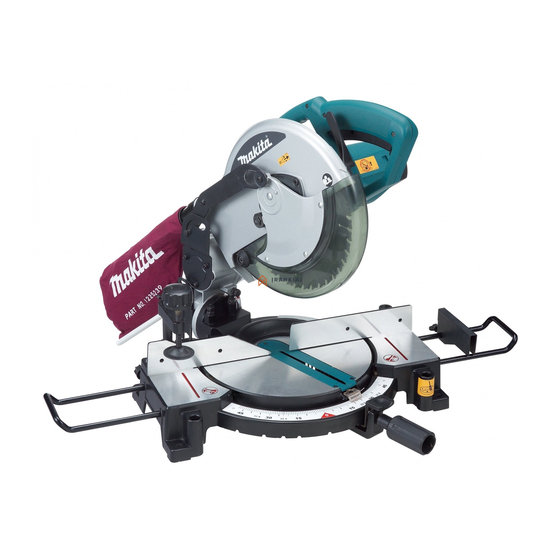
- Page 1 INSTRUCTION MANUAL Compound Miter Saw MT230 015058 DOUBLE INSULATION IMPORTANT: Read Before Using.
-
Page 2: Specifications
Electronic Makita declares that the following Machine(s): Equipment and its implementation in Designation of Machine: accordance with national law, electric Compound Miter Saw equipment that have reached the end of Model No./ Type: MT230 their life must be collected separately... -
Page 3: General Power Tool Safety Warnings
Conforms to the following European Directives: Do not abuse the cord. Never use the cord for 2006/42/EC carrying, pulling or unplugging the power tool. They are manufactured in accordance with the following Keep cord away from heat, oil, sharp edges or standard or standardized documents: moving parts. -
Page 4: Miter Saw Safety Warnings
19. Do not use the power tool if the switch does Wear hearing protection to reduce the risk of not turn it on and off. Any power tool that cannot hearing loss. be controlled with the switch is dangerous and Wear gloves for handling saw blade (saw must be repaired. -
Page 5: Installation
27. Do not use the tool in the presence of 45. To reduce the emitted noise, always be sure flammable liquids or gases. The electrical that the blade is sharp and clean. operation of the tool could create an explosion and 46. -
Page 6: Bench Mounting
Bench mounting FUNCTIONAL DESCRIPTION When the tool is shipped, the handle is locked in the lowered position by the stopper pin. Release the stopper CAUTION: pin by lowering the handle slightly and pulling the stopper Always be sure that the tool is switched off and •... -
Page 7: Adjusting The Miter Angle
1. Blade guard 1. Top surface of turn base 2. Periphery of 130mm blade 3. Guide fence 001782 007831 CAUTION: Kerf board After installing a new blade, always be sure that the • 1. Kerf board blade does not contact any part of the lower base when the handle is lowered completely. -
Page 8: Switch Action
WARNING: 1. Pointer NEVER use tool without a fully operative switch • trigger. Any tool with an inoperative switch is HIGHLY DANGEROUS and must be repaired before further usage. ASSEMBLY CAUTION: 007757 Always be sure that the tool is switched off and •... -
Page 9: Dust Bag
Sub-fence (for European countries only) 1. Hex bolt 2. Wrench 1. Sub-fence 007770 To install the blade, mount it carefully onto the spindle, 015064 making sure that the direction of the arrow on the surface This tool is equipped with the sub-fence. Usually position of the blade matches the direction of the arrow on the the sub-fence inside. -
Page 10: Securing Workpiece
Securing workpiece OPERATION WARNING: It is extremely important to always secure the workpiece • properly and tightly with the vise. Failure to do so can cause the tool to be damaged and/or the workpiece to be destroyed. PERSONAL INJURY MAY ALSO RESULT. Also, after a cutting operation, DO NOT raise the blade until the blade has come to a complete stop. - Page 11 Miter cutting Cutting aluminum extrusion Refer to the previously covered "Adjusting the miter 1. Vise angle". 2. Spacer block Bevel cut 3. Guide fence 4. Aluminum extrusion 5. Spacer block 001844 When securing aluminum extrusions, use spacer blocks or pieces of scrap as shown in the figure to prevent deformation of the aluminum.
-
Page 12: Carrying Tool
Stopper pin is for carrying and storage purposes • Cutting repetitive lengths only and not for any cutting operations. 1. Set plate MAINTENANCE 2. Screw 3. Holder CAUTION: Always be sure that the tool is switched off and • unplugged before attempting to perform inspection or maintenance. -
Page 13: Replacing Carbon Brushes
1. Triangular rule 1. Pointer 015063 007757 45° bevel angle Bevel angle 0° bevel angle 1. 45 ゚ bevel angle adjusting bolt 1. 0 ゚ adjusting bolt 2. Pointer 007751 Adjust the 45° bevel angle only after performing 007752 0° bevel angle adjustment. To adjust left 45° Lower the handle fully and lock it in the bevel angle, loosen the knob and tilt the blade lowered position by pushing in the stopper pin. -
Page 14: After Use
1. Brush holder cap 2. Screwdriver 007756 After use After use, wipe off chips and dust adhering to the • tool with a cloth or the like. Keep the blade guard clean according to the directions in the previously covered section titled "Blade guard". Lubricate the sliding portions with machine oil to prevent rust. - Page 16 Makita Jan-Baptist Vinkstraat 2, 3070, Belgium Makita Corporation Anjo, Aichi, Japan www.makita.com JM2308B083...
Need help?
Do you have a question about the MT230 and is the answer not in the manual?
Questions and answers