Table of Contents
Advertisement
Quick Links
Remote Monitoring GSM/SMS
Communicating Wireless Alarm System
G5
Installation & Operating
Instructions
Disposal and Recycling
Disposal of this product is covered by the Waste Electrical or Electronic Equipment (WEEE)
Directive. It should not be disposed of with other household or commercial waste.
At the end of its useful life the packaging and product should be disposed of via a suitable
recycling centre. Please contact your local authority or the retailer from where the product
was purchased for information on available facilities.
www.responseelectronics.com
miGuard Customer Helpline
Response Electronics Limited
0345 257 1000
Roman House, Lysons Avenue, Ash Vale, Surrey, GU12 5QF
email: info@responseelectronics.com
lines open 0900 to 1700 Monday to Friday
@ResponseLTD
MGG5_V4_1549
Advertisement
Table of Contents

Related Manuals for Response Electronics miGuard G5


Summary of Contents for Response Electronics miGuard G5
- Page 1 Please contact your local authority or the retailer from where the product was purchased for information on available facilities. www.responseelectronics.com miGuard Customer Helpline Response Electronics Limited 0345 257 1000 Roman House, Lysons Avenue, Ash Vale, Surrey, GU12 5QF email: info@responseelectronics.com...
-
Page 2: Table Of Contents
Contents Congratulations on your purchase of the miGuard G5 Alarm System. miGuard G5 Alarm System Overview --------------------------------------------- Before you commence installation we recommend that you unpack the Control Panel --------------------------------------------------------------------- product, familiarise yourself with the component parts, and carefully read... - Page 3 Apple and Android App ------------------------------------------------------- Pet Friendly PIR Sensor --------------------------------------------------------- 16~17 34~38 PIR Sensor Overview --------------------------------------------------------------- Adding an Account ---------------------------------------------------------------- LED Indicator ------------------------------------------------------------------------- G5 Alarm App overview ---------------------------------------------------------– PIR Sensor (inside) ----------------------------------------------------------------- Changing the App Language ------------------------------------------------------ Infrared Sensors Setting up the Alarm System (with the App and SMS) ----------------------- 18~31 Tamper Switch...
-
Page 4: Miguard G5 Alarm System Overview
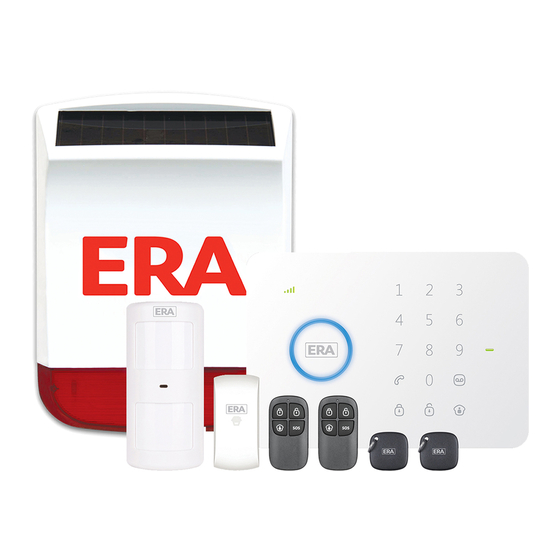
G5 Alarm System Overview In the Box: Rear View 1 x Control Panel Microphone Tamper Switch Loudspeaker 1 x Pet Friendly PIR Motion Sensor 1 x Door/Window Sensor 2 x Remote Controls 2 x RFID Tags 1 x Power Adapter 1 x Desk Stand, 1 x Wall Mount All Batteries &... -
Page 5: Accessories
Accessories Alarm System Operation The miGuard G5 Alarm System includes the Accessories shown below: The Alarm System receives a signal when a Sensor is triggered. The Control Panel will sound the alarm when armed and send SMS texts to all stored text numbers. When texting is finished the Control Panel will call the stored phone numbers and play the pre-recorded message. -
Page 6: Sensors
Sensors Grouping sensors Each Sensor can be set to a different mode. Four different modes can be selected; Sensor placement Home Mode, Normal Mode, Single Delay Mode or 24-hour Mode. When planning your Alarm System installation consider the most vulnerable areas of IMPORTANT: Determine which Mode each Sensor should be set to prior to your home such as exit/entry routes - well placed sensors will ensure optimum security... -
Page 7: Sensors Zone Names
Getting Started Single Delay Mode: One or more Sensors can be set in Single Delay Mode and will alarm at the specified time after being triggered. This Mode is usually used for Door/Window Sensors. For example, if the user does not want to carry the Remote Control, they can set Inserting a SIM card * the Door/Window Sensor to Single Delay Mode with the delay time set to 30 seconds. -
Page 8: Turning On The Control Panel
Turning on the Control Panel Plug the Power Adapter into the Power Adapter Socket underneath the Control Panel battery cover - then slide the power switch to `On' (see diagram on page 8). GSM Network Connection Indicator ‘0’ Disarm After switching on the system, the network indicator flashes once every second. This ‘1’... -
Page 9: Control Panel Operation
Control Panel Operation Naming RFID Tags For identification purposes RFID Tags can be named as shown in the example below Arming the system (Normal Mode) (Vicky). If someone arms or disarms the alarm system with an RFID Tag their name will be sent to the pre-stored RFID text number, followed by the arm/disarm message. -
Page 10: Speed Dial
Speed dial Disarming the alarm system by SMS When you press the system will dial the preset speed dial number immediately. The The main menu, received after texting ‘?’, will display the command for disarming the call ends when you press again. -
Page 11: Two-Way Talk
Two-way talk Apple and Android App Text ‘3’ to the telephone number of the SIM card in the Control Panel. You will be called back by the system and will be able to listen and speak to the person there. The G5 alarm system can also be operated with an App. -
Page 12: G5 Alarm App Overview
G5 Alarm App overview Setting up the Alarm System ( with the App and SMS) All Smartphone screenshots are taken from the iOS App and are accurate at the time of going to print. Android screens may vary. The alarm system can be set using the G5 Alarm App, as well as by sending text messages. -
Page 13: Store Emergency Telephone Numbers
Store emergency telephone numbers Store emergency SMS numbers Emergency numbers are the telephone numbers which will be called when the Emergency SMS numbers are the numbers that will receive texts when the alarm is alarm is activated. Text ‘5’ to the Control Panel to receive the current settings. activated. -
Page 14: Store Sms Number For Rfid Tags
Store SMS number for RFID Tags Store speed dial number The SMS number for an RFID Tag is the number the text message will be sent to when In this menu you can assign a phone number that will be stored as speed dial number. a RFID Tag is used to arm or disarm the system. -
Page 15: Renaming Sensors
Renaming Sensors Change RFID Tag name Each Sensor is on a zone. The names of the first 9 zones (1-9) can be changed The Control Panel can be set to notify the nominated SMS number when the first 4 RFID according to personal preference. -
Page 16: Change Entry/Exit Delay Time
Change entry/exit delay time Setting alarm volume and duration Both alarm volume and duration of the siren can be adjusted in this menu. The system can be armed with a time delay. When a delay time is set you will hear a beep every second as a warning of this delay. -
Page 17: Change Disarm Password
Change disarm password Setting Single Zone delay time Any Sensor can be set to ‘Single Zone Delay’. Text ‘13’ to the Control Panel. Text ‘14’ to the Control Panel. Copy the message enter your new password as example below Copy the message: adjust the delay time as example below: Disarm password(4-6 digits): Disarm password(4-6 digits):... -
Page 18: Delete Wireless Accessories
Delete Wireless Accessories Delete all Remote Controls by SMS All Remote Controls can be deleted by texting ‘23’ to the SIM card number in the Control All Accessories (Wireless Sensors, RFID Tags and Remote Controls) can be deleted Panel. from the system by entering the user code on the Control Panel and holding down the Full Arm button until two beeps are heard (3 seconds). -
Page 19: Arm & Disarm By Free Phone Call
Arm & Disarm by free phone call Remote Control To arm the alarm system by free phone call, call the SIM card telephone number in the Control Panel. When you hear the dial tone hang up. The Control Panel will be armed Remote Control overview and will call you back with 2 rings to confirm. -
Page 20: Home Mode (Part-Arm)
Home Mode (Part-arm) Pet Friendly PIR Sensor PIR Sensor overview Press . All sensors in the normal group will be armed. All sensors in the home group will be inactive. This means you can part arm the house. Mute Mode 1. -
Page 21: Pir Sensor (Inside)
PIR Sensor (back) PIR Sensor (inside) Test Mode LED ON / OFF Infrared Sensor Jumper Switch After self-testing, press the test button once. The PIR Sensor will emit a detection signal (LED flash once). The Sensor will stay in that mode for 3 minutes and detect a movement every 10 seconds. -
Page 22: Installing A Pir Sensor
Installing a PIR Sensor PIR Sensor Test Mode Avoid installing the Sensor directly facing a window, near air conditioning, heating, a Once the Sensor is fully installed and active it can be tested. Press the test button refrigerator, oven, in direct sunlight and places where the temperature fluctuates. once and walk from left to right or right to left in the room. -
Page 23: Led Indicator
LED Indicator IMPORTANT: The triangle on the Transmitter and the triangle on the Blink once : Door/window open detected Magnet must face each other. Blink once per 3 seconds : Low battery indication, please change the batteries immediately. Connecting a Door/Window Sensor to the Control Panel Note: When the battery level is low the administrator will receive a SMS notification. -
Page 24: Control Panel Installation
Control Panel Installation Technical Specifications Control Panel Power Supply 12V DC 500mA GSM Frequency 850 / 900 / 1800 / 1900MHz Standby Current ≤ 110mA Wall Mount Desk Stand Alarm Current ≤ 340mA Wall Mount Transmitting Distance ≤ 80m(open area/no interface) When mounting the Control Panel to the wall, first install the wall mount using the screws supplied, then slide the Control Panel into the wall mount in an upward motion. -
Page 25: Wireless Pir Motion Sensor
Wireless PIR Motion Sensor Wireless Door/Window Magnetic Sensor Power Supply 3V DC (2 x AA 1,5V LR6) Power Supply 1,5V DC (1 x AA 1,5V LR6) Standby Current Standby Current ≤ 90uA ≤ 35uA ≤ 9.5mA ≤ 10mA Alarm Current Alarm Current Detection Range 8 m / 110°... -
Page 26: Wireless Remote Control
Wireless Remote Control Troubleshooting DC 3V in the first instance check that all device batteries are operational. Power Supply (1 x CR2025 button cell batter y) Transmit Current ≤ 7mA Problems Reason/Solution Wireless Transmitting Distance ≤ 80 m (open field/no interference) Confirm whether the power supply is connected correctly Control Panel Radio Frequency... -
Page 27: Troubleshooting
Troubleshooting SMS notification not Check if RFID SMS notification number and RFID Tags sent when swiping Make sure the SIM card is inserted correctly names are stored RFID Tags Insert the SIM card prior to powering up Sensors, Remote The tamper switch could have been pressed three times The Control Panel Controls and other Check that the SIM card is to the correct GSM standard... -
Page 28: Cautions
Warranty Terms Cautions Always follow the instructions in the manual. Incorrect or improper uses of the device The one year warranty applies to all miGuard products unless otherwise specified at may result in injury. the time of purchase. When buying a second-hand miGuard product the product warranty remains measured from the time it was bought by the original owner. -
Page 29: Notes
Notes Download the G5 Alarm App Group Sensor type Sensor Name Normal Home 24/7 Single Door/window Zone 1 Sensor Zone 2 Motion Sensor Zone 3 Zone 4 Zone 5 Zone 6 Zone 7 Zone 8 Zone 9 Zone 10 Zone 11 Zone 12 Zone 13 Zone 14... - Page 30 Overview microSD Card (Not included) Download the App 2. Pairing Camera with WiFi through App Support 32GB microSD card maximum; please do not insert the Download the App by searching “IP116 camera” from Apple Store • Front View card after the camera is powered on. or Google Play.
- Page 31 Settings Installation Specification Password All the successfully paired phones have the same authority as Image sensor Sony 1/3” CMOS Sensor administrator who can view and set the camera (including changing Important: This camera should be placed where the WiFi signal is strong the password), so it is recommended to pair the phones of users for optimal performance before installation.
Need help?
Do you have a question about the miGuard G5 and is the answer not in the manual?
Questions and answers
Does the siren operate when the batteries are running out