Table of Contents
Advertisement
TROJAN
®
MY SPACE MY TIME
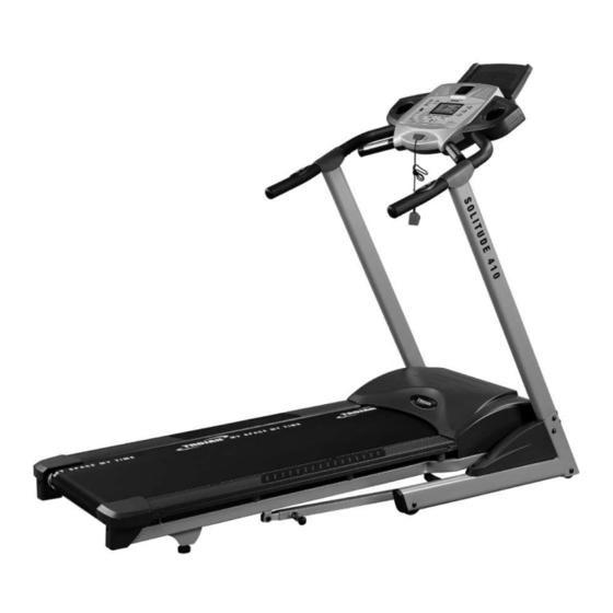
S O L I T U D E 41 0
T R E A D M I L L
TREADMILL CARE INSTRUCTIONS
AND ASSEMBLY MANUAL
WINNER, SHARON HAARHOFF,
USES TROJAN HOME FITNESS
EQUIPMENT AS PART OF
HER DAILY FITNESS
PROGRAM
SHARON HAARHOFF
CAUTION
READ ALL PRECAUTIONS AND
INSTRUCTIONS IN THIS MANUAL
BEFORE USING THIS EQUIPMENT
1 YEAR
KEEP THIS MANUAL FOR
CALL
FUTURE REFERENCE
Advertisement
Table of Contents

Subscribe to Our Youtube Channel
Related Manuals for Trojan SOLITUDE 410


Summary of Contents for Trojan SOLITUDE 410
- Page 1 S O L I T U D E 41 0 T R E A D M I L L TREADMILL CARE INSTRUCTIONS AND ASSEMBLY MANUAL WINNER, SHARON HAARHOFF, USES TROJAN HOME FITNESS EQUIPMENT AS PART OF HER DAILY FITNESS PROGRAM SHARON HAARHOFF...
-
Page 2: Table Of Contents
MAINTENANCE GROUNDING INSTRUCTIONS COMPUTER FUNCTIONS FITNESS TIPS & TECHNIQUES 10. CONDITIONING GUIDELINES 11. WARM - UP AND COOL - DOWN 12. FREQUENTLY ASKED QUESTIONS 13. PARTS LIST 14. EXPLODED DRAWING 15. TROJAN 1 YEAR LIMITED WARRANTY 16. TROJAN REPAIRS PROCEDURE... -
Page 3: Safety Instructions
11. Never operate the TROJAN SOLITUDE 410 TREADMILL if it has a damaged cord or plug, if it is not working properly, if it has been dropped and damaged, or exposed to water. -
Page 4: Pre Assembly Check List
2. PRE ASSEMBLY CHECK LIST Thank you for choosing the TROJAN SOLITUDE 410 TREADMILL. We take great pride in producing this quality product and hope it will provide many hours of quality exercise to make you feel better, look better and enjoy life to its fullest. -
Page 5: Hardware List
3. HARDWARE LIST DESCRIPTION DESCRIPTION Phillips Head Screw (M5 x 10 m/m) x 3pcs Button Head Socket Bolt (5/16”x1/2”) x12pcs Flat Washer (5/16” x 18 x 1.5T) x 4pcs Curved Washer (5/16” x 23 x 1.5T) x 4pcs Lubricant x 1pc Safety Key x 1pc Combination M5 Allen Wrench &... -
Page 6: Assembly Steps
4. ASSEMBLY STEPS Step 01 • Take the treadmill out of the carton and lay in on a level floor. Step 02 • Connect the Lower Computer Cable (53) and the Middle Computer Cable (54). Step 03 • Insert the Left and Right Handrails (4, 5) into the Frame Base (2). -
Page 7: Connect The Middle Computer Cable (54) And The Upper
4. ASSEMBLY STEPS Step 04 • Connect the Middle Computer Cable (54) and the Upper Computer Cable (55). • Connect the Speed Adjustment Switch Cable (46) with the Upper Speed Cable (59). • Connect the Incline Adjustment Switch Cable (47) with the 46 59 Incline Cable (60). -
Page 8: Folding Instructions
5. UNFOLDING / FOLDING / TRANSPORT UNFOLDING Hold the treadmill running board with your left hand. Pull the locking knob with your right hand and slowly lower the treadmill running board. Remove your right hand as you slowly lower the running board to the floor. (Figure 1) FOLDING Ensure the incline angle of the treadmill is at its lowest position. -
Page 9: Maintenance
6. MAINTENANCE Your treadmill should require little maintenance other then periodically applying lubricant. Lubricating under the treadbelt will ensure superior performance and extend the treadmill’s life expectancy. HOW TO CHECK TREADBELT FOR PROPER LUBRICATION Lift one side of the treadbelt and feel the top surface of the treadboard. -
Page 10: Grounding Instructions
7. GROUNDING INSTRUCTIONS This product must be grounded. If malfunction or breakdown occurs, grounding provides a path of least resistance for electric current to reduce the risk of electric shock. This product is equipped with a cord having an equipment-grounding conductor and a grounding plug. -
Page 11: Computer Functions
8. COMPUTER FUNCTIONS GETTING STARTED: Plug the treadmill into an appropriate wall outlet, then turn on the power switch located at the back of the treadmill just below the motor cover. Ensure that the safety key is installed, as the treadmill will not power on without it. WINDOW DISPLAY SPEED: Displays the current running speed from 1Km/h - 16Km/h (1Mph-10Mph). -
Page 12: Pulse Grip Feature
8. COMPUTER FUNCTIONS Operation: STEP 1: Attach the Safety key to activate the display (if not already on), the upper big window will display P0 (Manual). Press the ST/SP button to begin the belt movement at 1.0 km (1Mph). The consol will begin a 3 second count down before the belt starts moving. During training all parameters will be counting up. - Page 13 8. COMPUTER FUNCTIONS: PRESET PROGRAMMES 10107M-13...
-
Page 14: Fitness Tips & Techniques
9. FITNESS TIPS AND TECHNIQUES AEROBIC EXERCISE Aerobic exercise is any sustained activity that sends oxygen to your muscles via your heart and lungs. Aerobic exercise improves the fitness of your lungs and heart - your body’s most important muscle. Aerobic exercise fitness is promoted by any activity that uses your large muscles (arms, legs, or buttock, for example). -
Page 15: Conditioning Guidelines
10. CONDITIONING GUIDELINES How you begin your exercise program depends on your physical condition. If you have been inactive for several years, or are severely overweight, you must start slowly and increase your time on the equipment; a few minutes per workout. Initially, you may be able to exercise only for a few minutes in your target zone, however, your aerobic fitness will improve over the next six to eight weeks. -
Page 16: Warm-Up And Cool-Down
11. WARM-UP AND COOL-DOWN WORKOUT GUIDELINES Each workout should include the following three parts: A warm-up, consisting of 5 to 10 minutes of stretching and light exercise. A proper warm-up increases your body tem- perature, heart rate, and circulation in preparation for exercise. Training zone exercise, consisting of 20 to 30 minutes of exercising with your heart rate in your training zone. -
Page 17: Frequently Asked Questions
• Turn off computer, unplug, leave for 30 seconds, then restart the treadmill. • If the error persists please contact our call centre on 0861 876 526 (0861 Trojan) Q2. My consol is showing E1 • Memory of the consol is malfunctioning or the CPU is having accessing problems. -
Page 18: Parts List
13. PARTS LIST 13. PARTS LIST DESCRIPTION O’TY DESCRIPTION O’TY Main Frame Frame Base Cap (R) Frame Base Top Motor Cover Incline Bracket Rear Adjustment Base (L) Right Handrail Rear Adjustment Base (R) Left Handrail Handpulse Assembly Console Support 28~1 Handpulse Assembly (Top) Outer Slide 28~2 Handpulse Assembly (Bottom) Inner Slide... - Page 19 13. PARTS LIST DESCRIPTION O’TY DESCRIPTION O’TY Computer Cable (Lower) (1150m/m) Flat Washer (3/8” x 25 x 2T) Computer Cable (Middle) (1200m/m) Flat Washer (5 x 13 x 1.0T) Computer Cable (Upper) (800m/m) Nylon Washer (B) (ø50 x ø13 x 3T) Sensor w/ Cable (1000 m/m) Nylon Washer (A) (ø10 x ø25 x 3T) Sensor Rack...
-
Page 20: Exploded Drawing
14. EXPLODED DRAWING 14. EXPLODED DRAWING 10107M-20 10107M-20... -
Page 21: Trojan 1 Year Limited Warranty
15. TROJAN 1 YEAR LIMITED WARRANTY Masstores (Pty)Ltd (“the Supplier”) hereby provides a limited warranty to the original purchaser of this product (“the Consumer”) that this product will be free of manufacturing defects in materials and workmanship which under normal,... -
Page 22: Proof Of Purchase
The Consumer does not need to return the product to the store. The Consumer shall phone the Trojan hotline on 0861 Trojan (0861 876 526) and the Supplier’s authorized agent will at its discretion either repair the item at the Consumer’s residence or collect and repair the item at their premises. -
Page 23: Trojan Repairs Procedure
16. TROJAN REPAIRS PROCEDURE 1. Procedure for repairs Should you experience any faults or breakdowns on your Trojan equipment, please adhere to the following procedure to have the fault rectified speedily and professionally. • Do not return the product to the store* •...
Need help?
Do you have a question about the SOLITUDE 410 and is the answer not in the manual?
Questions and answers
What year did the 410 manufactured