Table of Contents
Advertisement
Quick Links
Advertisement
Table of Contents

Related Manuals for COMAC ULTRA 85BS


Summary of Contents for COMAC ULTRA 85BS
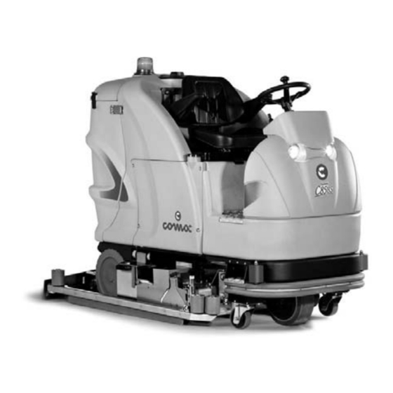
- Page 1 MANUAL USE AND MAINTENANCE ULTRA 85BS ED. 01-2010 Doc. 10012827 Ver.
- Page 2 The contained descriptions in the present publication are not binding. The company therefore reserves itself the right to bring in whatever moment possible organs changes, details or supplies of accessories, that it holds convenient for an improvement, or for any demand of constructive or commercial character.
-
Page 3: Table Of Contents
CONTENTS ON CONSIGNMENT OF THE MACHINE ........................4 SERIAL NUMBER PLATE ............................4 INTRODUCTORY COMMENT .............................4 TECHNICAL DESCRIPTION ............................5 SYMBOLS USED ON THE MACHINE ........................6 SYMBOLS USED IN THE MANUAL..........................9 GENERAL SAFETY REGULATIONS........................10 MACHINE PREPARATION............................11 1. HANDLING THE PACKED MACHINE ..........................11 2. -
Page 4: On Consignment Of The Machine
On consignment of the machine Serial number plate When the machine is delivered to the customer, an immediate check must be performed to ensure all the material mentioned in the shipping documents has been received, and also to check the machine has not been damaged during transportation. -
Page 5: Technical Description
TECHNICAL DESCRIPTION ULTRA 85BS Working width Lateral movement of base Work capacity sq.m/h 5500 Cylindrical brushes (2) Ø xl mm 210x867 Cylindrical brushes rpm Pressure on cylindrical brushes max 80 Maximum specific pressure Grs/sq.cm Cylindrical brush motors 2x1300 Cylindrical brush motor... -
Page 6: Symbols Used On The Machine
SYMBOLS USED ON THE MACHINE Symbol denoting solenoid valve open Used on the instrument panel, to indicate the solenoid valve switch Symbol denoting solution tank empty Used on the instrument panel, for the red indicator light showing a low level of water in the solution tank Symbol denoting brush base rise/fall Used on the instrument panel, for the yellow indicator light showing the brush command jack is... - Page 7 SYMBOLS USED ON THE MACHINE Symbol denoting brush lever Used on the instrument panel, to indicate the lever of the brush base. Longitudinal movements are accompanied by vertical movements of the base. Symbol denoting squeegee rise/fall Used on the instrument panel, to indicate the squeegee rise/fall lever Symbol denoting squeegee fully down Used on the instrument panel, for the green indicator light showing the squeegee is on the floor Symbol denoting ammetric check of the brush motor...
- Page 8 SYMBOLS USED ON THE MACHINE Symbol denoting automatic or manual work mode Used on the instrument panel, to indicate the switch for operating the squeegee in automatic or manual mode Symbol denoting forwards and backwards direction lever Used on the instrument panel, to indicate the machine direction lever Symbol denoting on or off Used on the instrument panel, to indicate the key switch for machine operation on (I) or off (O) Symbol denoting incorrect functioning...
-
Page 9: Symbols Used In The Manual
SYMBOLS USED IN THE MANUAL Indicates the disposal methods Respect the regulations Indicates danger of gas exhalation and leakage of corrosive liquids Indicates the danger of fire Do not go near with free flames... -
Page 10: General Safety Regulations
The machine does not cause harmful vibrations When your COMAC machine has reached the end of its long working life, dispose of the materials it contains (especially oils and electronic components), and bearing in mind that the machine itself was constructed using 100% recyclable materials ... -
Page 11: Machine Preparation
The packages cannot be placed on top of each other. The total weight is 630 kg The overall dimensions of the package are: ULTRA 85BS 1760 mm 1335 mm 2135 mm 2. HOW TO UNPACK THE MACHINE 1. -
Page 12: Fitting The Batteries Into The Machine
MACHINE PREPARATION 3. FITTING THE BATTERIES INTO THE MACHINE The batteries must be housed in the special compartment beneath the operator's seat. They should be handled using lifting equipment that is suitable in terms of both weight and hook-up system. They must also satisfy the requirements of Standard CEI 21-5. -
Page 13: Connecting The Battery Charger
MACHINE PREPARATION 5. CONNECTING THE BATTERY CHARGER The connector is placed in the lower left section (in relation to the operator). The lower part (1), connected to the batteries, must be inserted in the upper connector (2), fixed to the cables of the battery charger. The coupling connector is consigned inside the bag containing this instruction booklet, and must be assembled on the cables of the battery charger as indicated in the instructions (see the battery charger manual). -
Page 14: Squeegee
MACHINE PREPARATION 8. SQUEEGEE For packaging reasons, the squeegee may be supplied disassembled. It must be assembled as shown in the figure, tightening the small columns (1) on the threaded pins of the squeegee, in the special housings on the squeegee support Insert the suction tube in the squeegee sleeve and fix it with the special clamp (2) During working operation, the rear rubber is slightly tilted backwards (by about 5mm) in a uniform way for its whole length. -
Page 15: Assembling The Brushes
MACHINE PREPARATION 10. ASSEMBLING THE BRUSHES 1. Connect the battery connector 2. Turn the key to the ON position 3. Use the lever to raise the base 4. Turn the key to the OFF position and remove it from the panel (carrying out the brush assembly operation with the power supply connected may cause injuries to the hands) 5. -
Page 16: Detergent Solution
MACHINE PREPARATION 11. DETERGENT SOLUTION Fill the solution tank with clean water at a temperature no greater than 50°C and add liquid detergent in the proper concentration, following the instructions of the manufacturer. The formation of excess foam could damage the suction motor, so use only the minimum amount of detergent necessary. -
Page 17: Work
WORK 1. Carry out the operations to prepare the machine 2. Sit on the driver’s seat 3. Check the parking brake is released (1) 4. Connect the battery connector (2) 5. Turn the key of the main switch to I (3). The red indicator light (3) of the motor will immediately begin to flash on the instrument panel, and the battery display (4) will switch on. - Page 18 WORK 10. Position the selector on forwards (9) 11. Select the advance speed by turning the knob 12. Turn the lever (10) clockwise to turn on the tap. The water indicator light only switches on during the advance phase 13. Position the brush lever downwards (1) to lower the base. During the descent, the indicator lights of the jack and the brush motor will switch on.
-
Page 19: Checking The Brush Motor
WORK CHECKING THE BRUSH MOTOR The brush motor is checked electronically. If it reaches established overload limits, the red indicator light (1) on the instrument panel starts to flash. After a few seconds the motor stops and the indicator light of the brush switch goes off. To start up the motor again, turn the main switch key (2) off and on again. -
Page 20: Automatic-Manual Squeegee
WORK AUTOMATIC - MANUAL SQUEEGEE Automatic: if the switch is placed on automatic, the squeegee lowers and the suction motor starts up when the machine moves forwards. In the same way, the squeegee rises and the suction motor stops when the machine moves backwards. Manual: if the switch is placed on manual, the squeegee has to be lifted and lowered manually by means of the switch (2). -
Page 21: At The End Of The Work
AT THE END OF THE WORK At the end of the work, and before carrying out any type of maintenance, perform the following operations: 1. turn off the tap 2. raise the base 3. switch off the brush motor switch 4. -
Page 22: Daily Maintenance
DAILY MAINTENANCE CLEANING THE HOPPER Remove the pin of the right-hand side bar, and turn the bar outwards (1) Release the pin of the hopper (2) This operation must be carried out using gloves to protect against contact with dangerous solutions Remove the hopper, remembering to clean the filter (3) Reassemble everything, carrying out the above-mentioned operations in the reverse order... -
Page 23: Cleaning The Recovery Tank
DAILY MAINTENANCE CLEANING THE RECOVERY TANK 5. Empty the tank by means of the flexible tube, turning the knob a couple of times to loosen it and then removing the cap (1) 6. To empty the tank quickly, loosen and remove the side plug (2) This operation must be carried out using gloves to protect against contact with dangerous solutions Open the hinge that fixes the tanks (3) -
Page 24: Cleaning The Squeegee
DAILY MAINTENANCE CLEANING THE SQUEEGEE 1. Raise the squeegee by pressing the command lever forwards (1) 2. Remove the suction tube from the squeegee sleeve (2) 3. Remove the pins from the left and right squeegee bars (3) 4. Loosen the small fixing columns (4) 5. - Page 25 DAILY MAINTENANCE 12. With the base up, release the side bar from its support 13. Loose the knob (1) and take out the movable brush support plate (2) 14. Check the state of wear and tear of the bristles of the cylindrical brushes 15.
-
Page 26: Weekly Maintenance
WEEKLY MAINTENANCE CLEANING THE SUCTION TUBE Whenever suction seems to be unsatisfactory, check that the suction tube is not obstructed. If necessary, clean it with a water jet introduced from the side where it is connected to the tank. Proceed as follows: 1. -
Page 27: Adjusting The Side Bars
WEEKLY MAINTENANCE ADJUSTING THE SIDE BARS It is necessary to adjust the height of the side bars at regular intervals. This operation must be carried out with the base lowered. 1. Loosen the knob (1) 2. Tighten the register (2) to raise the side bar, or loosen it (2) to lower the side bar 3. -
Page 28: Insufficient Water On The Brushes
TROUBLESHOOTING INSUFFICIENT WATER ON THE BRUSHES 1. Check the tap is turned on 2. Check the solenoid valve switch is on 3. Check there is water in the solution tank (“RESERVE” indicator light off) 4. Clean the solution filter THE MACHINE DOES NOT CLEAN WELL 1. -
Page 29: The Suction Motor Does Not Function
TROUBLESHOOTING THE SUCTION MOTOR DOES NOT FUNCTION 1. Check the suction motor switch is on 2. Check whether the recovery tank is full and, if necessary, empty it 3. Check the float switch is working correctly. With the recovery tank empty, the mobile float must be disconnected from the upper contact (see also “CLEANING THE RECOVERY TANK FILTER”... -
Page 30: Choosing And Using The Brushes
CHOOSING AND USING THE BRUSHES POLYPROPYLENE BRUSH (PPL) Used on all types of floors. Good resistance to wear and tear, and hot water (no greater than 60°C). The Polypropylene brush is non-hygroscopic and therefore retains its characteristics even when working in wet conditions. NYLON BRUSH Used on all types of floors. -
Page 31: Ec Declaration Of Conformity
San Giovanni Lupatoto, 15/01/2010 COMAC S.p.A. Legal representative Giancarlo Ruffo COMAC spa Via Cà Nova Zampieri, 5 – 37057 San Giovanni Lupatoto – Verona – ITALY Tel. +39 045 8774222 – Fax +39 045 8750303 – E-mail: com@comac.it or info@comac.it - www.comac.it...
Need help?
Do you have a question about the ULTRA 85BS and is the answer not in the manual?
Questions and answers