
Related Manuals for Chamberlain LA500U


Summary of Contents for Chamberlain LA500U
- Page 1 TROUBLESHOOTING GUIDE for 2016 UL 325 Compliant Gate Operators LA500U LA400U LA412U CSW24U CSL24U RSL12U RSW12U CSW200U SL3000U SL585U SL595U LiftMaster 845 Larch Avenue Elmhurst, IL 60126-1196...
-
Page 2: Table Of Contents
MODELS SL585U AND SL595U (THREE PHASE) ........21 2016 UL COMPLIANT GATE OPERATORS ..........2 MODEL LA412U ...................22 MODEL LA400U ...................23 BASIC TROUBLESHOOTING MODEL LA500U ...................24 MULTI-METERS ..................3 MODELS CSL24U AND CSW24U ............25 TRANSFORMERS ...................4 MODELS RSL12U AND RSW12U ............26 RELAYS ....................5 EXPANSION BOARD SWITCH SETTINGS ..........5... -
Page 3: Before You Begin
BEFORE YOU BEGIN 2016 UL COMPLIANT GATE OPERATORS New UL 325 standards for vehicular gate operators go into effect in January of 2016. The new standard will require gate operators to monitor for fault conditions of external entrapment devices. LiftMaster has not only updated their line of gate operators to meet the new UL 325 standard, they have also taken the opportunity to add a common user interface and common feature sets across the line to increase performance, safety and accessibility. -
Page 4: Basic Troubleshooting
BASIC TROUBLESHOOTING MULTI-METERS The image is an example of a generic multimeter. LiftMaster currently has no intended affiliations with this multi-meter manufacturer. This is not an endorsement for this particular meter model. When shopping for a meter, look for a meter able to fit in a shirt pocket or clip on a belt. -
Page 5: Transformers
The output rating has nothing to do with the required amount of electricity to make the accessory function. TYPE OF TRANSFORMERS MODELS Plug-in Transformer LA400U, RSL12U, RSW12U Toroid Transformer LA500U, CSL24U, CSW24U Block Transformer CSW200U, SL3000U, SL585U, SL595U... -
Page 6: Relays
BASIC TROUBLESHOOTING RELAYS EXPANSION BOARD RELAYS In gate operators, relays are often used to either control certain operator functions or activate/deactivate ancillary devices such as heaters or lights. When electricity is applied to a relay coil, it energizes a magnet and will close a Normally Open switch or open a Normally Closed switch. A relay typically has prongs labeled COMM , NO, NC, and two prongs to power the relay coil. -
Page 7: Capacitor (For Ac Operators)
BASIC TROUBLESHOOTING To protect against fire and electrocution: • DISCONNECT power (AC or solar and battery) BEFORE installing or servicing operator. CAPACITOR (FOR AC OPERATORS) SYMPTOM: A bad capacitor will cause a motor to hum when trying to run, or stall while it is running. CHECK THE CAPACITOR: Disconnect ALL power from operator. -
Page 8: Dc Motors
BASIC TROUBLESHOOTING To protect against fire and electrocution: • DISCONNECT power (AC or solar and battery) BEFORE installing or servicing operator. DC MOTORS SYMPTOM: The motor will not run. CHECK THE MOTOR: Disconnect ALL power from operator. Disconnect the gate from the operator. 12V MOTOR 24V MOTOR DIAGNOSTICS... -
Page 9: Ac Motors
BASIC TROUBLESHOOTING To protect against fire and electrocution: • DISCONNECT power (AC or solar and battery) BEFORE installing or servicing operator. AC MOTORS SYMPTOM: The motor will not run. CHECK THE MOTOR: Disconnect ALL power from operator. Disconnect the gate from the operator. Unplug the motor harness from the board and measure the resistance of the motor. -
Page 10: Erase Memory
BASIC TROUBLESHOOTING ERASE MEMORY ERASE ALL REMOTE CONTROLS 1. Press and release the LEARN button (operator will beep and green XMITTER LED will light). 2. Press and hold the LEARN button again until the green XMITTER LED flashes and then release the button (approximately 6 seconds). All remote control codes are now erased. -
Page 11: Diagnostic Codes
DIAGNOSTIC CODES To protect against fire and electrocution: For continued protection against fire: • DISCONNECT power (AC or solar and battery) BEFORE installing or • Replace ONLY with fuse of same type and rating. servicing operator. DIAGNOSTIC CODES NOTE: When cycling or disconnecting power (ac/dc) to the control board, it is recommended that you unplug the J15 plug. OPEN, CLOSE, &... - Page 12 DIAGNOSTIC CODES Some codes are saved in the code history and some are not. If a code is not saved it will briefly appear on the display as it occurs, then disappear. When servicing of the operator is complete, erase the code history by pressing the STOP button until the display flashes “Er” then “CL” (about 6 seconds).
- Page 13 Code 43. Shadow Loop Error All Operators: Gate will not close. Models LA400U, LA412U, LA500U, RSW12U: Gate will not open. Interrupt Loop Error Gate will not close. Wireless edge battery The operator will beep 2 times Replace batteries in wireless edge.
- Page 14 DIAGNOSTIC CODES Some codes are saved in the code history and some are not. If a code is not saved it will briefly appear on the display as it occurs, then disappear. When servicing of the operator is complete, erase the code history by pressing the STOP button until the display flashes “Er” then “CL” (about 6 seconds).
- Page 15 DIAGNOSTIC CODES Some codes are saved in the code history and some are not. If a code is not saved it will briefly appear on the display as it occurs, then disappear. When servicing of the operator is complete, erase the code history by pressing the STOP button until the display flashes “Er” then “CL” (about 6 seconds).
- Page 16 DIAGNOSTIC CODES Some codes are saved in the code history and some are not. If a code is not saved it will briefly appear on the display as it occurs, then disappear. When servicing of the operator is complete, erase the code history by pressing the STOP button until the display flashes “Er” then “CL” (about 6 seconds).
-
Page 17: Solar
SOLAR SOLAR TROUBLESHOOTING SYMPTOM The operator alarm will beep three times with a command and the BATT LOW LED will be on when the solar panel is not charging the battery. SOLUTIONS • Check that the correct number of solar panels are connected to the operator. 12V operators require one 10W 12V panel up to a maximum of three 10W 12V panels. -
Page 18: 24V Applications
SOLAR 24V APPLICATIONS Disconnect all power (AC, solar, battery) to the operator before servicing. NOTE: 10W 12V solar panels are illustrated in the image below. 33AH BATTERIES To “BATT DC POWER” input on control board ITEMS NEEDED FOR 24V APPLICATIONS J15 Plug Diode (solar panel... -
Page 19: Applications
SOLAR 12V APPLICATIONS Disconnect all power (AC, solar, battery) to the operator before servicing. NOTE: 10W 12V solar panels are illustrated in the image below. ONE 7AH BATTERY ITEMS NEEDED FOR 12V APPLICATIONS To “BATT DC POWER” input on control board J15 Plug (battery connections) (solar panel... -
Page 20: Power
POWER MODELS CSW200U AND SL3000U MODEL CSW200U MODEL SL3000U POWER BOARD (located behind control board) CONTROL BOARD BIPART DELAY OPEN OPEN AC POWER SWITCH LEFT RIGHT CONTROL BOARD HANDING JUNCTION BOX AC POWER SWITCH JUNCTION BOX ANTENNA CURRENT MOTOR DRIVE RPM &... -
Page 21: Models Sl585U And Sl595U (Single Phase)
POWER MODELS SL585U AND SL595U (SINGLE PHASE) CONTROL BOARD MODEL SL595U MODEL SL585U BIPART CONTROL BOARD POWER BOARD DELAY CONTROL BOARD POWER BOARD OPEN OPEN LEFT RIGHT HANDING AC POWER SWITCH JUNCTION JUNCTION BOX MOTOR DRIVE 24 VAC IN ANTENNA CURRENT RPM &... -
Page 22: Models Sl585U And Sl595U (Three Phase)
POWER MODELS SL585U AND SL595U (THREE PHASE) CONTROL BOARD MODEL SL595U MODEL SL585U BIPART CONTROL BOARD DELAY POWER BOARD CONTROL BOARD POWER BOARD OPEN OPEN LEFT RIGHT HANDING AC POWER SWITCH JUNCTION JUNCTION BOX Check the transfomer and MOTOR DRIVE RPM &... -
Page 23: Model La412U
POWER MODEL LA412U SYMPTOM: Operator does not have power. CONTROL BOX CONTROL BOARD Check the solar panels.* CONTROL BOARD Check the control board.* Check the voltage coming from Try replacing the fuse. the solar panels (red and black If that does not work, replace wires on the J15 plug labeled the control board. -
Page 24: Model La400U
POWER MODEL LA400U SYMPTOM: Operator does not have power. OUTLET HOUSING CONTROL BOX CONTROL BOARD CONTROL BOARD Check the control board.* Try replacing the fuse. If that does not work, replace Incoming Power DIAGNOSTICS the control board. (Back of Outlet Housing) Outlet Outlet Check the transformer.*... -
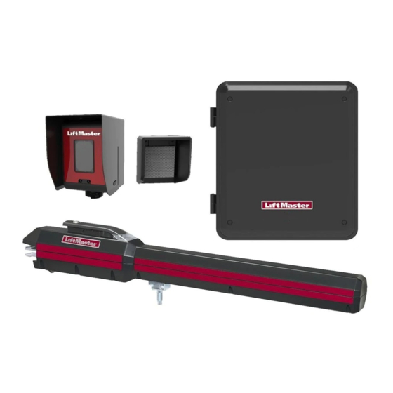
Page 25: Model La500U
POWER MODEL LA500U SYMPTOM: Operator does not have power. CONTROL BOX CONTROL BOARD TRANSFORMER BRIDGE RECTIFIER Incoming Power AC POWER SWITCH CONTROL BOARD Check the control board. Try replacing the fuse on the control board. If that does not Check the transformer.* work, replace the control board. -
Page 26: Models Csl24U And Csw24U
POWER MODELS CSL24U AND CSW24U SYMPTOM: Operator does not have power. MODEL CSL24U MODEL CSW24U CONTROL BOARD CONTROL BOARD OUTLET HOUSING OUTLET HOUSING BATTERIES BATTERIES TRANSFORMER and BRIDGE RECTIFIER located on chassis, behind the electrical box. TRANSFORMER and BRIDGE RECTIFIER located on chassis, behind the electrical box. -
Page 27: Models Rsl12U And Rsw12U
POWER MODELS RSL12U AND RSW12U SYMPTOM: Operator does not have power. (Back of Outlet Housing) DIAGNOSTICS Check the control board.* Try replacing the fuse on Outlet the control board. If that does not work, replace the control board. Fuse CONTROL BOARD OUTLET HOUSING Outlet J15 Plug... -
Page 28: Myq
® FREQUENTLY ASKED QUESTIONS What do I need to activate the gate operator using MyQ ® a. Router b. Internet connection c. Internet Gateway d. Internet Gateway serial number (located on the bottom of the Internet Gateway) e. MyQ-Enabled Gate Operator What is an Internet Gateway? The Internet Gateway (828LM), is a 900 MHz Internet Protocol device for monitoring and controlling MyQ devices (e.g. - Page 29 ® FREQUENTLY ASKED QUESTIONS Can the Internet Gateway be connected from a remote location using the Wide Area Network (WAN) to our corporate offices and access the Internet from the corporate location? ® If the Internet Gateway is successfully connected to the MyQ server (green LED on MyQ Gateway is illuminated and solid), the MyQ app can monitor and control a MyQ device from any location.
-
Page 30: Troubleshooting Myq
® ® TROUBLESHOOTING MyQ If issues are experienced when adding an Internet Gateway, a LiftMaster Gate Operator or light control to a MyQ ® account, please review the troubleshooting topics below. CONNECTION ISSUES PROBLEM If the green LED on the Internet Gateway is not illuminated or blinking, the Internet Gateway is not connected to the Internet. SOLUTION There are a few different reasons an Internet Gateway will not successfully connect to the Internet: •... -
Page 31: Myq ® Account Issues
® ® ACCOUNT ISSUES Unable to add more than one MyQ device to a MyQ account: • Prior to adding MyQ devices, an account must be established. An account can be created by visiting MyLiftMaster.com or by downloading the MyQ app from a smartphone or tablet app store. -
Page 32: Myq ® Account Issues
® ® ACCOUNT ISSUES PROBLEM The MyQ-Enabled Gate Operator will not respond to the app. SOLUTION • Confirm the green LED on the Internet Gateway is illuminated and solid. If the green LED is not illuminated or blinking, see Connection Issues section. -
Page 33: Myq ® Error Codes
® ® ERROR CODES Below are potential error codes that may be encountered when working with the Internet Gateway, MyQ ® app, MyQ website, or your PC or smartphone. GENERAL ERROR CODES ERROR CODE MESSAGE ISSUE AND RESOLUTION Unable to remove device. •... - Page 34 ® ® ERROR CODES Below are potential error codes that may be encountered when working with the Internet Gateway, MyQ ® app, MyQ website, or your PC or smartphone. GENERAL ERROR CODES ERROR CODE MESSAGE ISSUE AND RESOLUTION The device* is currently in •...
-
Page 35: Incompatible Router And Switch
® INCOMPATIBLE ROUTER AND SWITCH INCOMPATIBLE ROUTER When installing an Internet Gateway, issues have been identified with the following routers/modems: MANUFACTURER MODEL ® Belkin F5D8236-4 (Only works on LAN ports 1 & 3) D-Link ® DIR-665 Hauwei ® Router/Modem Echolife HG520C ®... - Page 36 845 Larch Avenue Elmhurst, Illinois 60126-1196 LiftMaster.com PAS002 © 2015, LiftMaster – All Rights Reserved...
Need help?
Do you have a question about the LA500U and is the answer not in the manual?
Questions and answers