Table of Contents
Advertisement
INSTALLATION
AND SERVICING
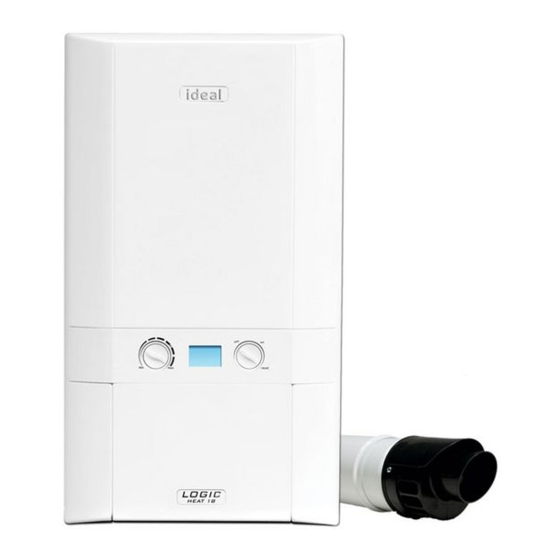
Project
Heat
15 & 24
For users guide see reverse of book
For details of document amendments, refer to page 3
When replacing any part on this appliance, use only spare parts that you can be
assured conform to the safety and performance specification that we require.
Do not use reconditioned or copy parts that have not been clearly authorised by Ideal.
For the very latest copy of literature for specification and maintenance practices visit our
website www.idealboilers.com where you can download the relevant information in PDF format.
January 2014
UIN 252412 A02
November 2009
UIN 204626 A03
Advertisement
Table of Contents

Related Manuals for IDEAL Project Heat 15


Summary of Contents for IDEAL Project Heat 15
- Page 1 Do not use reconditioned or copy parts that have not been clearly authorised by Ideal. For the very latest copy of literature for specification and maintenance practices visit our website www.idealboilers.com where you can download the relevant information in PDF format.
- Page 2 Project Heat - Installation and Servicing...
- Page 3 New updated Commissioning Checklist & Service Record Sheets page 60 & 61 New pages added, Flowchart for CO Level and Combustion Ratio Check on Commissioning a Condensing Boiler Ideal Stelrad Group reserve the right to vary specification without notice Project Heat - Installation and Servicing...
- Page 4 general Table 1 - general Data project heat Gas supply 2H - G20 - 20mbar Gas Supply Connection 15mm copper compression Injector Size (mm) 4.15 4.15 Flow Connection Central Heating 22mm copper compression Return Connection Central Heating 22mm copper compression Flue Terminal Diameter - Turret mm (in) 100 (4)
-
Page 5: Table Of Contents
general Project Heat CONTENTs Natural gas only air supply ..............9 Boiler size g.C. appliance No. pI No. Benchmark Commissioning Checklist ..... 58 (Benchmark No.) Boiler Clearances ............10 41-750-57 86 CL 08 Boiler Exploded Diagram ........... 15 Condensate Drain .......... 9,29,30,46 41-750-58 86 CL 08 Commissioning &... -
Page 6: Safe Handling
general saFE haNDLINg INTRODUCTION This boiler may require 2 or more operatives to move it to its The project heat range of boilers are wall mounted, full installation site, remove it from its packaging base and during sequence, automatic spark ignition, low water content, fanned movement into its installation location. -
Page 7: Air Supply
Installation and Servicing Instructions or as otherwise recommended by Ideal stelrad group in writing. If in doubt In both cases, details of essential features of cupboard / please enquire. - Page 8 general gas sUppLy 4. Where the lowest part of the terminal is fitted less than 2m (6’6”) above a balcony, above ground or above a flat roof The local gas supplier should be consulted, at the installation to which people have access then the terminal MUST be planning stage, in order to establish the availability of an adequate protected by a purpose designed guard.
-
Page 9: Electrical Supply
general ELECTRICaL sUppLy TERMINaL Warning. The terminal assembly can be adapted to accommodate various This appliance must be earthed. wall thicknesses. Refer to Frame 1 . Wiring external to the appliance MUST be in accordance with the current I.E.E. (BS.7671) Wiring Regulations and any local aIR sUppLy regulations which apply. - Page 10 general BOILER DIMENsIONs, sERVICEs & CLEaRaNCEs all dimensions in mm The boiler connections are made on the boiler connection tails. Refer to Frame 34. wall thicknesses do not exceed 600mm (24”). Where the The following minimum clearances must be maintained for space into which the boiler is going to be installed is less operation and servicing.
- Page 11 Should these conditions not apply either lower the pump position or raise the cistern above the minimum requirement specified by Return & flow Ideal stelrad group. The isolation valves should be fitted as close to the connections load 30 - 60 = 22 mm pump as possible.
- Page 12 general LOW hEaD aND LaRgE sysTEMs WITh ExTENsIVE pIpE RUNs - OpEN VENT This arrangement is useful for large systems where radiators at the extremities are difficult to vent. This can lead to pumping over with conventional feed and vent arrangements.
- Page 13 general sEaLED sysTEM REqUIREMENTs - continued 4. Expansion Vessel A diaphragm type expansion vessel must be include a non-return valve and a stop valve with an connected to a point close to the inlet side of the automatic air vent connected between them, the stop pump, the connecting pipe being not less than 15 mm valve being located between the system and the ”...
-
Page 14: Water Treatment
Benchmark Guidance Notes on Water Treatment in Central Heating Runcorn, Cheshire WA7 4QX Systems. Tel: 0800 389 4670 If water treatment is used Ideal stelrad group recommend only the use www.sentinel-solutions.net of Scalemaster Gold 100, FERNOX, MB-1, ADEy MC1 or SENTINEL-X100... - Page 15 INSTALLATION 10 BOILER assEMBLy - Exploded View Note that item numbers are linked to the spares list HEAT EXCHANGER DRAIN FLUE MANIFOLD ELECTRODE DETECTION FLOW SENSOR FLUE MANIFOLD TOP IGNITOR UNIT PIPE - FLOW FLUE MANIFOLD - TOP SEALING CAP IGNITION LEAD PIPE - RETURN FLUE MANIFOLD - REAR SEALING CAP...
- Page 16 INSTALLATION 11 UNpaCKINg The boiler is supplied fully assembled in Pack A. A telescopic or non-telescopic flue assembly for rear or side flue outlet in Pack B is suppled as a separate order. Unpack and check the contents. pack a Contents Boiler Hardware Pack Box Wall Mounting Plate...
- Page 17 INSTALLATION UNpaCKINg..CONT’D Note. This flue system incorporates a removable flue outlet nose that utilises a push fit location system. This enables the installation of deflector, high level or balcony outlet flue kits without the removal of the whole ‘B’ pack terminal. The appliance must not be operated without the desired outlet nose correctly fitted in place.
-
Page 18: Mounting The Boiler
INSTALLATION 14 WaLL MOUNTINg TEMpLaTE The wall mounting template is located on the internal protective Extended centre line Extended centre line packaging. The template shows the position of the fixing and rear 1 5 5 1 5 5 “A” - See Diagram in “A”... - Page 19 INSTALLATION 18 DETERMININg ThE FLUE LENgTh aND FLUE paCKs REqUIRED IMPORTANT. The boiler must be installed in a vertical position in accordance to the installation instructions. FLUE KITs Telescopic Flue‘B’ pack - contains: Flue turret, telescopic flue incorporating a terminal and rubber wall seals. horizontal Flue Terminal (600mm long) ‘B’...
- Page 20 INSTALLATION 19 DETERMININg ThE FLUE LENgTh aND FLUE paCKs REqUIRED..CONT’D 90º Elbow Kit 60/100 - (Equivalent flue length resistance = 1M) 45º Elbow Kit 60/100 - (Equivalent flue length resistance = 0.6M) Minimum horizontal Flue Lengths (Centre line of turret to outside of wall terminal) Telescopic Flue ‘B’ Pack = 400mm Horizontal Flue terminal (600mm long) ‘B’...
- Page 21 INSTALLATION 21 CUTTINg & sETTINg ThE FLUE LENgTh TELEsCOpIC FLUEs TELEsCOpIC FLUE B paCK SHOULD ONLy BE ADJUSTED FOR USE WITHIN ITS SPECIFIED RANGE AND MUST NOT BE CUT hORIzONTaL FLUE TERMINaL (1000MM LONg) B paCK (TELEsCOpIC) MUST ONLy BE CUT IF REQUIRED FLUE LENGTHS ARE BETWEEN 602 &...
- Page 22 INSTALLATION 22 INsTaLLINg ThE FLUE FITTINg FLUE ThROUgh ThE WaLL 1. Measure wall thickness and add 14mm. 2. Measure from the outer terminal lip towards the end of outer flue, place a small location mark at the dimension acquired at point 1. 3.
- Page 23 INSTALLATION 23 REAR FLuE OuTLET KIT (55/80) ASSEMBLy - ExPLODED VIEW LEgEND 1. Duct Assembly 2. Plastic Connector 3. Wall Mounting Plate 24 TERMINAL WALL SEAL ASSEMBLy/POSITIONINg Prior to fitting the flue, the rubber terminal wall seal provided Once the flue is installed it is IMPORTANT that the rubber in the flue pack MUST be fitted to the flue terminal as shown terminal wall seal is pressed against the outside wall to create below in Figure 1.
- Page 24 INSTALLATION 26 FITTINg THE WALL PLATE/REAR FLuE TERMINAL ASSEMBLy 1. Ensure the rubber terminal wall seal is fitted to the terminal. Refer to Frame 28. 2. Insert the previously cut to length terminal assembly into the plastic connector. 3. Line up the mark on the top of the plastic connector with the top of the terminal (marked with a label).
- Page 25 INSTALLATION 27 MOuNTINg THE BOILER - REAR FLuE OuTLET KIT (55/80) 1. Remove the rear flue blanking disk. 2. Lift the boiler onto the wall plate, (refer to the introduction section for safe handling advice), ensuring the boiler is offered to the bracket tabs at an angle as shown below, and carefully allow the boiler to swing down to the wall as this movement engages the rear flue air and flue seal.
- Page 26 INSTALLATION 28 FITTINg ThE OpTIONaL ROOF FLUE KIT (Flat or pitched) Note. A flat or pitched roof flashing plate (not supplied) is required before proceeding with the installation of this kit. This kit is suitable for both flat and pitched roof terminations, using a concentric flue to run vertically from the top of the boiler and terminating above roof level.
-
Page 27: Flue Terminal Position
INSTALLATION 30 FLUE TERMINaL pOsITION The terminal should be positioned so that products of combustion can safely disperse at all times. pluming may occur at the termination so, where possible, terminal positions where this could cause a nuisance should be avoided. Minimum dimensions are shown below 300mm 625mm... - Page 28 INSTALLATION 31 assEMBLINg ThE ROOF FLUE KIT Determine the correct height that the flue should terminate above the roof. If after calculating or measuring the overall flue height from the top of the boiler, it is necessary to cut both pipes of assembly A, then ensure they are cut equally leaving the inner flue tube longer than the outer air tube as supplied.
- Page 29 INSTALLATION 32 CONDENsaTE DRaIN Condensate pump Where gravity discharge to an internal termination is not physically possible or where very long internal pipe runs would be required to reach a suitable discharge point, a condensate pump of a specification recommended by the boiler or pump manufacturer should be used terminating into a suitable internal foul water discharge point such as an internal soil and vent stack or internal kitchen or bathroom waste pipe etc.
-
Page 30: Installation And Servicing
INSTALLATION 33 CONDENsaTE DRaIN - CONT’D..Figure 3 - Connection of a Condensate Pump Typical Figure 4 - Connection of condensate Drainage Pipe to Method (see manufacturers detailed instructions) External Soil & Vent Stack Boiler Water/weather Visible air break with 75mm proof insulation Boiler sealed... -
Page 31: Electrical Connections
INSTALLATION 34 CONNECTIONs NOTEs. Ensure all pipe blanking plugs are removed before connecting. Return Flow WaTER CONNECTIONs The boiler flow and return pipes are supplied fitted to the boiler and ready for top connection. note. For heating loads in excess of 17.6kW (60,000 Btu/h) use 28mm x 22mm connectors to connect the boiler flow and return pipes to 28mm. - Page 32 INSTALLATION 36 INTERNaL INsTaLLER WIRINg The Project Heat boiler must be connected to a permanent live supply and NOT switched by thermostats/programmers. To install the mains cable: 1. Isolate the mains supply to the boiler. 2. Remove the front panel. Refer to Frame 12. 3.
-
Page 33: External Electrical Controls
INSTALLATION 37 WIRINg ThE sysTEM pUMp noTe. The appliance musT be Wired WiTh a permanenT live supply. The sysTem pump musT be Wired To The boiler. The boiler WarranTy Will be invalid iF This requiremenT is noT complied WiTh. 1. Isolate the mains supply to the boiler. 2. - Page 34 INSTALLATION 39 WIRINg DIagRaM Project Heat - Installation and Servicing...
-
Page 35: Commissioning & Testing
INSTALLATION 40 COMMIssIONINg aND TEsTINg B. gas Installation a. Electrical Installation 1. The whole of the gas installation, including the meter, 1. Checks to ensure electrical safety should be carried out by a should be inspected and tested for tightness and purged in competent person. -
Page 36: Electrical Supply
INSTALLATION 41 INITIaL LIghTINg Legend a. CH temperature control B. Mode Control Knob C. Boiler Status D. Burner ‘on’ indicator E. Gas Inlet Pressure Test Point F. Gas Service Cock Gas Supply 205862-10076 1. Check that the system has been filled and that the boiler is not valve will adversely affect operation and render our airlocked. -
Page 37: Handing Over
INSTALLATION 42 gENERaL ChECKs Make the following checks for correct operation: CENTRaL hEaTINg (Ch) MODE WaTER CIRCULaTION sysTEM 1. Ensure that the CH external controls are 1. With the system COLD, check that the initial pressure is correct to the system calling for heat. -
Page 38: Servicing Schedule
Ensure all caps and seals have been verified and the inlet gas pressure (and gas are re-fitted after use rate) have been verified, then contact Ideal. 11. Complete the service section in the Benchmark Commissioning Checklist. Project Heat -... -
Page 39: Boiler Front Panel Removal/Replacement
SERVICING 46 BOILER FRONT PANEL REMOVAL / REPLACEMENT REMOVaL 1. Loosen the two screws retaining the front panel. 2. Pull the two spring clips down to disengage and pull panel forward and upward and remove. REpLaCEMENT 3. Hook the panel onto the top retaining clips. 4. -
Page 40: Burner Removal And Cleaning
SERVICING 48 BURNER REMOVaL aND CLEaNINg 1. Ensure the sump is fully drained 2. Undo the two screws and remove the sump cover retaining the lower flue manifold. 3. Lift the manifold to clear the bottom sealing gasket and remove manifold. -
Page 41: Cleaning The Heat Exchanger
SERVICING 50 CLEaNINg ThE hEaT ExChaNgER note: Ensure the condensate trap/siphon is fully drained before cleaning. Refer to Ignition Electrode Flame Detection Frame 49. 1. Remove ignition and flame detection electrodes. Refer to Frames 57 & 58. 2. It is advisable to replace the sump cover prior to the water flush process. -
Page 42: Fault Finding
SERVICING 52 REpLaCEMENT OF COMpONENTs gENERaL After replacing ANy component check operation of the boiler, including gas soundness, gas rate and combustion When replacing aNy component test. 1. Isolate the electricity supply. IMpORTaNT. When work is complete, the front panel must be correctly 2. - Page 43 SERVICING 54 BURNER INJECTOR REpLaCEMENT 1. Refer to Frame 52. 2. Disconnect the electrical leads from the fan. 3. Undo the gas pipe union connection to the injector housing. 4. Loosen the screw retaining the fan mounting bracket. 5. Lift and remove the fan and venturi assembly. 6.
- Page 44 SERVICING 56 CONTROL & RETURN ThERMIsTOR RENEWaL 1. Refer to Frame 52. 2. Disconnect the electrical leads from the thermistors. 3. Unclip the flow thermistor from the flow pipe and withdraw it from the boiler. 4. Unclip the return thermistor from the return pipe and withdraw it from the boiler.
- Page 45 SERVICING 58 FLaME DETECTION ELECTRODE REpLaCEMENT 1. Refer to Frame 52. 2. Remove the burner. Refer to Frame 55. 3. Unplug the flame detection lead from the Flame Detection Electrode electrode. 4. Remove the 2 screws retaining the detection electrode. 5.
- Page 46 SERVICING 60 gas CONTROL VaLVE REpLaCEMENT 1. Refer to Frame 52. 2. Unplug the electrical lead connection from the gas control valve and disconnect the earth wire. 3. Undo the union nut on the outlet of the gas control valve. 4.
- Page 47 SERVICING 62 MaIN pCB REpLaCEMENT Note that production boiler PCBs are factory pre-set to operate for boiler range and output, but when ordering Primary PCB as a spare, an additional Boiler Chip Card (BCC) MUST also be purchased for your specific boiler range and output. Note.
- Page 48 SERVICING 63 UsER CONTROL pCB REpLaCEMENT Note. Fit the earth strap provided with the PCB to your wrist and a suitable earth on the boiler chassis. 1. Refer to Frame 52. 2. Remove the main PCB, refer to Frame 66. 3.
- Page 49 SERVICING 65 hEaT ENgINE RENEWaL - Refer also to Frame 10 - ‘Boiler Exploded View’ Note. To remove the flow and return pipe connections from the heat exchanger, it may be necessary to cut the pipes above the boiler. IMpORTaNT Before starting the removal procedure, protect the gas and electrical controls with a waterproof sheet or plastic bag.
- Page 50 Fault Finding 67 FaULT FINDINg ChaRT MaIN MENU In order to assist fault finding the boiler has a 7 segment display. The key to the display codes is as follows: gO TO FRaME 68 - aLTERNaTINg ‘L’ and ‘1’ FLOW TEMpERaTURE OVERhEaT LOCKOUT gO TO FRaME 69 - aLTERNaTINg ‘L’...
- Page 51 Fault Finding 68 aLTERNaTINg ‘L’ aND ‘1’ - FLOW TEMpERaTURE OVERhEaT LOCKOUT Is the Boiler and CH System filled with water and all Fill and vent the system and open all isolation valves, isolation and radiator valves open? then reset boiler Is the pump wired back to the boiler? Wire pump back to boiler.
- Page 52 Fault Finding 71 aLTERNaTINg ‘F’ aND ‘2’ - FLaME LOss Is the Gas Pressure available at Does the boiler ignite for a short Check gas supply and the Boiler Inlet (18 mbar)? time and then extinguish? rectify fault Check wiring from gas Is 215Vdc supply available at the valve to PCB for continuity.
- Page 53 Fault Finding 75 aLTERNaTINg ‘F’ aND ‘6’ - OUTsIDE sENsOR FaULT Securely connect the wiring at both the Is the wiring securely connected at both the boiler and boiler and Outside Sensor Outside Sensor? Fit a new Outside Sensor Disconnect the wires to the outside sensor. Check the resistance using a suitable multimeter Is wiring securely connected between the incoming terminal connected across the Outside Sensor’s terminal pins.
- Page 54 Fault Finding 79 NO Ch OpERaTION Move the mode knob to the ON position Is the mode knob in the ON position? Switch the Timer and Room Thermostat On Are the Timer and the Room Thermostat switched on? Open the Radiator Valves Are the Radiator Valves Open? Is there 230Vac at (A)? There is no Voltage from the Timer/Room...
-
Page 55: Spare Parts Info
When replacing any part on this appliance use only spare parts that you can be assured conform to the safety and performance specification that we require. Do not use reconditioned or copy parts that have not been clearly authorised by Ideal. Failure to do so could affect safety or performance of this appliance. -
Page 56: Spare Parts
SPARE PARtS Project Heat - Installation and Servicing... - Page 57 Benchmark Commissioning and Servicing Section It is a requirement that the boiler is installed and commissioned to the manufacturers instructions and the data fields on the commissioning checklist completed in full. To instigate the boiler guarantee the boiler needs to be registered with the manufacturer within one month of the installation.
-
Page 58: Gas Boiler System Commissioning Checklist
GAS BOILER SYSTEM COMMISSIONING CHECKLIST This Commissioning Checklist is to be completed in full by the competent person who commissioned the boiler as a means of demonstrating compliance with the appropriate Building Regulations and then handed to the customer to keep for future reference. CONTROLS Programmable room thermostat Optimum start control... -
Page 59: Service Record
SERVICE RECORD It is recommended that your heating system is serviced regularly and that the appropriate Service Interval Record is completed. Service Provider SERVICE 01 SERVICE 02 ² % ² % ² % ² % (Where Possible) (Where Possible) Signature Signature SERVICE 03 SERVICE 04... - Page 60 FLOWCHART FOR CO LEVEL AND COMBUSTION RATIO CHECK ON COMMISSIONING A CONDENSING BOILER Important Preliminary Information on Checks The air gas ratio valve is factory-set and must not be adjusted DURING COMMISSIONING. If the boiler requires conversion to operate with a different gas family (e.g. conversion from natural gas to LPG) sepa- rate guidance is provided with the conversion kit supplied and this must be followed.
- Page 61 0.2%? sampling point. Allow readings to stabilise before recording. Turn off appliance and call Ideal Technical Helpline for advice The appliance must not be commissioned until problems are identified CO level less and resolved. If commissioning cannot be fully completed, the appliance than 350ppm AND CO/CO must be disconnected from the gas supply in accordance with GSIUR.
- Page 62 & servicing of central heating systems FM 59915 Ideal Boilers Ltd., P.O. Box 103, National Ave, Kingston upon Hull, HU5 4JN. Telephone: 01482 492 251 Fax: 01482 448 858. Registration No. London 322 137. Ideal stelrad group pursues a policy of continuing improvement in the design and performance of its products.
-
Page 63: Users Guide
When replacing any part on this appliance, use only spare parts that you can be assured conform to the safety and performance specification that we require. Do not use reconditioned or copy parts that have not been clearly authorised by Ideal. -
Page 64: Minimum Clearances
Benchmark Commissioning Checklist. you can check your installer by calling Gas Safe Register direct on 0800 4085500. Ideal stelrad group is a member of the Benchmark scheme and fully supports the aims of the programme. Benchmark has been introduced to improve the standards of installation and commissioning of central heating systems in the UK and to encourage the regular servicing of all central heating systems to ensure safety and efficiency. -
Page 65: Frost Protection
operation To relight the boiler Repeat the procedure detailed in ‘To light the boiler’. control of Water Temperature The boiler controls the central heating radiator temperature to a Frost protection maximum of 80 C, adjustable via the temperature control (A). If no system frost protection is provided and frost is likely during The Project Heat is a high efficiency condensing boiler which is a short absence from home, leave the heating controls (if fitted) - Page 66 Condensate Drain escape of gas This appliance is fitted with a siphonic condensate trap system Should a gas leak or fault be suspected contact the National that reduces the risk of the appliance condensate from freezing. Gas Emergency Service without delay. Telephone 0800 111 However should the condensate pipe to this appliance freeze, please follow these instructions: Do NOT search for gas leaks with a naked flame.
-
Page 67: Troubleshooting
pOINTs FOR ThE BOILER UsER Note. In line with our current warranty policy we would ask that you check through the following guide to identify any problems external to the boiler prior to requesting a service engineers visit. Should the problem be found to be other than with the appliance we reserve the right to levy a charge for the visit, or for any pre-arranged visit where access is not gained by the engineer. -
Page 68: Fault Codes
Engineer if outside of the warranty period. In IE contact a Registered Gas Installer (RGII). Ideal Consumer Helpline Ideal stelrad group pursues a policy of continuing improvement in the design and performance of its products. The right is therefore reserved to vary specification without notice. Tel: 01482 498660 Ideal, P.O.
Need help?
Do you have a question about the Project Heat 15 and is the answer not in the manual?
Questions and answers