Table of Contents
Advertisement
Quick Links
MODEL INFORMATION . . . . . . . . . . . . . . . . . . . . . . . . . . . . . . . . . . . . . . . . . . . . . . . . . . 1.2
MODEL IDENTIFICATION . . . . . . . . . . . . . . . . . . . . . . . . . . . . . . . . . . . . . . . . . . . . . . . . 1.2
ENGINE DESIGNATION NUMBER . . . . . . . . . . . . . . . . . . . . . . . . . . . . . . . . . . . . . . . . . 1.2
VIN IDENTIFICATION . . . . . . . . . . . . . . . . . . . . . . . . . . . . . . . . . . . . . . . . . . . . . . . . . . . 1.2
ENGINE SERIAL NUMBER LOCATION . . . . . . . . . . . . . . . . . . . . . . . . . . . . . . . . . . . . . 1.2
VEHICLE SERIAL NUMBER (VIN) LOCATION . . . . . . . . . . . . . . . . . . . . . . . . . . . . . . . . 1.3
VEHICLE INFORMATION . . . . . . . . . . . . . . . . . . . . . . . . . . . . . . . . . . . . . . . . . . . . . . . . . 1.4
PUBLICATION NUMBERS . . . . . . . . . . . . . . . . . . . . . . . . . . . . . . . . . . . . . . . . . . . . . . . . 1.4
REPLACEMENT KEYS . . . . . . . . . . . . . . . . . . . . . . . . . . . . . . . . . . . . . . . . . . . . . . . . . . 1.4
SPECIAL TOOLS . . . . . . . . . . . . . . . . . . . . . . . . . . . . . . . . . . . . . . . . . . . . . . . . . . . . . . . 1.4
2009 GENERAL SPECIFICATIONS . . . . . . . . . . . . . . . . . . . . . . . . . . . . . . . . . . . . . . . . . 1.5
GENERAL: 2009 RANGER RZR / RZR S / INT'L. . . . . . . . . . . . . . . . . . . . . . . . . . . . . . . 1.5
DETAILED: 2009 RANGER RZR . . . . . . . . . . . . . . . . . . . . . . . . . . . . . . . . . . . . . . . . . . . 1.6
DETAILED: 2009 RANGER RZR S / INT'L. . . . . . . . . . . . . . . . . . . . . . . . . . . . . . . . . . . . 1.7
2010 GENERAL SPECIFICATIONS . . . . . . . . . . . . . . . . . . . . . . . . . . . . . . . . . . . . . . . . . 1.8
GENERAL: 2010 RANGER RZR . . . . . . . . . . . . . . . . . . . . . . . . . . . . . . . . . . . . . . . . . . . 1.8
DETAILED: 2010 RANGER RZR . . . . . . . . . . . . . . . . . . . . . . . . . . . . . . . . . . . . . . . . . . . 1.9
GENERAL: 2010 RANGER RZR S / INT'L . . . . . . . . . . . . . . . . . . . . . . . . . . . . . . . . . . . 1.10
DETAILED: 2010 RANGER RZR S / INT'L. . . . . . . . . . . . . . . . . . . . . . . . . . . . . . . . . . . 1.11
MISC. SPECIFICATIONS AND CHARTS . . . . . . . . . . . . . . . . . . . . . . . . . . . . . . . . . . . . 1.12
CONVERSION TABLE . . . . . . . . . . . . . . . . . . . . . . . . . . . . . . . . . . . . . . . . . . . . . . . . . . 1.12
STANDARD TORQUE SPECIFICATIONS. . . . . . . . . . . . . . . . . . . . . . . . . . . . . . . . . . . 1.13
SAE TAP / DRILL SIZES . . . . . . . . . . . . . . . . . . . . . . . . . . . . . . . . . . . . . . . . . . . . . . . . 1.14
METRIC TAP / DRILL SIZES . . . . . . . . . . . . . . . . . . . . . . . . . . . . . . . . . . . . . . . . . . . . . 1.14
DECIMAL EQUIVALENTS . . . . . . . . . . . . . . . . . . . . . . . . . . . . . . . . . . . . . . . . . . . . . . . 1.14
GLOSSARY OF TERMS. . . . . . . . . . . . . . . . . . . . . . . . . . . . . . . . . . . . . . . . . . . . . . . . . 1.15
GENERAL INFORMATION
GENERAL INFORMATION
CHAPTER 1
1
1.1
Advertisement
Chapters
Table of Contents
Troubleshooting

Related Manuals for Polaris 2010 Ranger RZR 800 EFI


Summary of Contents for Polaris 2010 Ranger RZR 800 EFI
-
Page 1: Table Of Contents
GENERAL INFORMATION CHAPTER 1 GENERAL INFORMATION MODEL INFORMATION ..........1.2 MODEL IDENTIFICATION . -
Page 2: Model Information
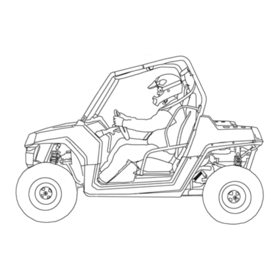
Vehicle and Engine Serial Number Location Whenever corresponding about a Polaris ORV, refer to the vehicle identification number (VIN) and the engine serial number. The VIN can be found stamped on a portion of the front left frame rail, close to the left front wheel (see Figure 1-1). -
Page 3: Vehicle Information
Special tools may be required while servicing this vehicle. Some of the tools listed or depicted are mandatory, while other tools maybe substituted with a similar tool, if available. Polaris recommends the use of Polaris Special Tools when servicing any Polaris product. -
Page 4: 2009 General Specifications
GENERAL INFORMATION 2009 GENERAL SPECIFICATIONS MODEL: 2009 RANGER RZR MODEL NUMBER: R09VH76AD, AG, AH, AM, AO, AS, AZ ENGINE MODEL: EH076OLE Category Dimension / Capacity Length 102 in. / 259 cm Width 50 in. / 127 cm Height 68.5 in. / 174 cm Wheel Base 77 in. - Page 5 Engine Displacement 760cc Shift Type In Line Shift - H / L / N / R / P Number of Cylinders Polaris Demand Drive Plus Front Gearcase Oil Requirements Bore & Stroke (mm) 80 x 76.5 mm 6.75 oz. (200 ml) Compression Ratio 9.78:1...
- Page 6 GENERAL INFORMATION MODEL: 2009 RANGER RZR S / INT’L MODEL NUMBER: R09VH76AX, FX ENGINE MODEL: EH076OLE Category Dimension / Capacity Length 106 in. / 269 cm Width 60.5 in. / 154 cm Height 70.5 in. / 179 cm Wheel Base 77 in.
- Page 7 760cc H.O. Shift Type In Line Shift - H / L / N / R / P Number of Cylinders Polaris Demand Drive Plus Front Gearcase Oil Requirements Bore & Stroke (mm) 80 x 76.5 mm 6.75 oz. (200 ml)
-
Page 8: 2010 General Specifications
GENERAL INFORMATION 2010 GENERAL SPECIFICATIONS MODEL: 2010 RANGER RZR MODEL NUMBER: R10VH76AD, AG, AJ, AT ENGINE MODEL: EH076OLE Category Dimension / Capacity Length 102 in. / 259 cm Width 50 in. / 127 cm Height 68.5 in. / 174 cm Wheel Base 77 in. - Page 9 Engine Displacement 760cc Shift Type In Line Shift - H / L / N / R / P Number of Cylinders Polaris Demand Drive Plus Front Gearcase Oil Requirements Bore & Stroke (mm) 80 x 76.5 mm 6.75 oz. (200 ml) Compression Ratio 9.78:1...
- Page 10 GENERAL INFORMATION MODEL: 2010 RANGER RZR S / INT’L MODEL NUMBER: R10VH76AW / R10VH76FX ENGINE MODEL: EH076OLE Category Dimension / Capacity Length 106 in. / 269 cm Width 60.5 in. / 154 cm Height 70.5 in. / 179 cm Wheel Base 77 in.
- Page 11 760cc H.O. Shift Type In Line Shift - H / L / N / R / P Number of Cylinders Polaris Demand Drive Plus Front Gearcase Oil Requirements Bore & Stroke (mm) 80 x 76.5 mm 6.75 oz. (200 ml)
-
Page 12: Misc. Specifications And Charts
GENERAL INFORMATION MISC. SPECIFICATIONS AND CHARTS Conversion Table °C to °F: (°C + 32) = °F °F to °C: (°F - 32) = °C 1.12... -
Page 13: Standard Torque Specifications
GENERAL INFORMATION Standard Torque Specifications The following torque specifications are to be used only as a general guideline. There are exceptions in the steering, suspension, and engine areas. Always consult the exploded views or each manual section for torque values of fasteners before using standard torque. 1.13... -
Page 14: Sae Tap / Drill Sizes
GENERAL INFORMATION SAE Tap / Drill Sizes Decimal Equivalents Metric Tap / Drill Sizes 1.14... -
Page 15: Glossary Of Terms
CC: Cubic centimeters. Center Distance: Distance between center of crankshaft and center of driven clutch shaft. Chain Pitch: Distance between chain link pins (No. 35 = 3/8" or 1 cm). Polaris measures chain length in number of pitches. CI: Cubic inches. - Page 16 GENERAL INFORMATION NOTES 1.16...
- Page 17 MAINTENANCE CHAPTER 2 MAINTENANCE PERIODIC MAINTENANCE CHART ......... 2.3 BREAK-IN PERIOD / MAINTENANCE CHART KEY .
- Page 18 MAINTENANCE STEERING ............2.29 STEERING WHEEL FREEPLAY .
-
Page 19: Periodic Maintenance Chart
Polaris dealer. = SEVERE USE ITEM: See information provided above. E = Emission Control System Service (California). NOTE: Inspection may reveal the need for replacement parts. Always use genuine Polaris parts. WARNING Improperly performing the procedures marked could result in component failure and lead to serious injury or death. -
Page 20: Pre-Ride - 25 Hour Maintenance Interval
Engine Oil Change 25 H 250 (400) Perform a break-in oil change at one month (Break-In Period) Perform these procedures more often for vehicles subjected to severe use. E Emission Control System Service (California) Have an authorized Polaris dealer perform these services. -
Page 21: 50 - 300 Hour Maintenance Interval
Change shock oil and seals Inspect periodically; adjust when parts are Toe Adjustment replaced Headlight Aim Adjust as needed Perform these procedures more often for vehicles subjected to severe use. E Emission Control System Service (California) Have an authorized Polaris dealer perform these services. -
Page 22: Component Inspection / Service Locations
MAINTENANCE COMPONENT INSPECTION / SERVICE LOCATIONS Front and Rear View Standard RZR Shown Standard RZR Shown... -
Page 23: Rh And Lh Side Views
MAINTENANCE RH and LH Side Views Standard RZR Shown Standard RZR Shown *Standard RZR Only... -
Page 24: Lubricants / Service Products
MAINTENANCE LUBRICANTS / SERVICE PRODUCTS NOTE: Each item can be purchased separately at your local Polaris dealer. Polaris Lubricants, Maintenance and Service Part No. Description Products Additives / Sealants / Thread Locking Agents / Misc. Part No. Description Loctite™ Threadlock 242... -
Page 25: Maintenance References
Semi-annually** Lube (PN 2871551) grease gun. Locate grease fittings on the upper and lower A-arms of Control Arm Pivot Polaris Premium All Season the front and rear suspension Page 2.6 Semi-annually** Bushings, FT / RR Grease (PN 2871423) and grease with grease gun. -
Page 26: General Vehicle Inspection And Maintenance
MAINTENANCE GENERAL VEHICLE INSPECTION Shift Cable Inspection / Adjustment AND MAINTENANCE Shift cable adjustment may be necessary if symptoms include: • No AWD or gear position display on instrument cluster Pre-Ride / Daily Inspection • Ratcheting noise on deceleration Perform the following pre-ride inspection daily, and when •... -
Page 27: Fuel System And Air Intake
MAINTENANCE Once the proper adjustment is obtained, place the shift Be sure fuel line is routed properly. cable and upper jam nut into the mount. Tighten the lower IMPORTANT: Make sure line is not kinked or pinched. jam nut against the mount. Replace fuel line every two years. -
Page 28: Throttle Pedal Inspection
MAINTENANCE Throttle Pedal Inspection Slide back the cable adjuster boot. Using a 10 mm open-end wrench, loosen the adjustment If the throttle pedal has excessive play due to cable stretch or jam nut. cable misadjustment, it will cause a delay in throttle speed. Also, the throttle may not open fully. - Page 29 MAINTENANCE 11. Lift up on the floor and remove the panduit strap retaining 20. Route the cable through the retainer at the bottom of the the throttle cable and brake line to the frame. frame in the floor console opening. 12.
-
Page 30: Air Filter Service
MAINTENANCE 24. Route the cable around the circumference of the PVT cover 33. Install the throttle body cover and PVT inlet duct. up and over to the throttle body. 34. Verify the vehicle is still in PARK. 25. Apply pipe sealant or PTFE Teflon® tape to the threads at 35. - Page 31 MAINTENANCE Inspect the air filter element and replace if necessary. Do Installation not attempt to clean the air filter with anything other that Clean the air box thoroughly. low pressure compressed air. Place the filter ring over the end of the filter and install the NOTE: If the filter has been soaked with fuel or oil it filter into the air box.
-
Page 32: Engine
MAINTENANCE ENGINE Lever Lock Engine Oil Level The twin cylinder engine is a wet-sump engine, meaning the oil is contained in the bottom of the crankcase. To check the oil level follow the procedure listed below: Dipstick SAFE ADD 8 OZ Dipstick Reinstall the dipstick completely, but do not lock it. -
Page 33: Engine Oil And Filter Service
MAINTENANCE Engine Oil and Filter Service NOTE: The sealing surface on the drain plug should be clean and free of burrs, nicks or scratches. Always change engine oil and filter at the intervals outlined in Reinstall drain plug and torque to 16 ft. lbs. (22 Nm). the Periodic Maintenance Chart. -
Page 34: Engine Breather Hose Inspection
MAINTENANCE Engine Breather Hose Inspection A smooth idle generally indicates good compression. Low engine compression is rarely a factor in running condition The engine is equipped with a breather hose. Inspect the problems above idle speed. breather hose for possible kinks or wear. The hose is form fit- A cylinder leakdown test is the best indication of engine ted for a proper fit. -
Page 35: Transmission And Gearcases
MAINTENANCE TRANSMISSION AND GEARCASES Transmission / Gearcase Specification Chart RAIN EVEL HECK EARCASE UBRICANT APACITY ORQUE ORQUE Transmission AGL - Synthetic ATV 24 oz. (710 ml) 40-50 ft. lbs. (54-68 Nm) 30-45 in. lbs. (3-5 Nm) (Main Gearcase) Gearcase Lubricant Transmission AGL - Synthetic ATV 14 oz. - Page 36 MAINTENANCE Main Gearcase - Lubricant Level Check: The fill plug is located on the side of the gearcase just below the shift lever bell crank. Maintain the fluid level even with the bottom of the fill plug hole. Position vehicle on a level surface. Remove the fill plug.
-
Page 37: Front Gearcase Lubrication
The drain plug is located on the bottom of the gearcase. Front Gearcase Specifications 8-10 ft. lbs. Fill Plug (11-14 Nm) Specified Lubricant: Polaris Demand Drive Plus (PN 2877922) Capacity: 6.75 oz. (200 ml) Fill Plug: 8-10 ft. lbs. (11-14 Nm) Drain Plug: 8-10 ft. lbs. (11-14 Nm) Drain Plug Lubricant Level Check: 8-10 ft. -
Page 38: Rear Gearcase Lubrication
MAINTENANCE Rear Gearcase Lubrication Lubricant Change: The drain plug is located on the bottom right side of the rear Rear Gearcase Specifications gearcase. Specified Lubricant: ATV Angle Drive Fluid (PN 2876160) RZR / RZR S Capacity: 26 oz. (769 ml) RZR S, INT’L Capacity: 22 oz. -
Page 39: Cooling System
Remove recovery bottle cap and add coolant using a funnel. Polaris Premium 60/40 is already premixed and ready to use. Do Fill recovery bottle to MAX level with Polaris 60/40 not dilute with water. -
Page 40: Cooling System Hoses
MAINTENANCE Cooling System Pressure Test Carefully straighten any bent radiator fins. Refer to Chapter 3 for cooling system pressure test procedure. Remove any obstructions with compressed air or low pressure water. Cooling System Hoses CAUTION Inspect all hoses for cracks, deterioration, abrasion or leaks. -
Page 41: Final Drive / Wheel And Tire
MAINTENANCE FINAL DRIVE / WHEEL AND TIRE Radiator Removal Remove the front bumper (see Chapter 5). Wheel, Hub, and Spindle Torque Table Remove the upper engine outlet hose and recovery hose from the top of the radiator. Item Nut Type Specification Remove the (2) upper radiator retaining bolts and the (4) Aluminum Wheels... -
Page 42: Tire Inspection
MAINTENANCE Carefully lower the vehicle to the ground. WARNING Torque the wheel nuts and/or hub nut to the proper torque specification listed in the torque table at the beginning of this section. Operating a RANGER with worn tires will increase the possibility of the vehicle skidding If hub nut was removed, install a new cotter pin after the easily with possible loss of control. -
Page 43: Electrical And Ignition System
MAINTENANCE ELECTRICAL AND IGNITION SYSTEM Battery Removal Remove the driver’s seat to access the battery. Battery Maintenance Keep battery terminals and connections free of corrosion. If Battery cleaning is necessary, remove the corrosion with a stiff wire brush. Wash with a solution of one tablespoon baking soda and one cup water. -
Page 44: Battery Off Season Storage
NOTE: Battery charge can be maintained by using a A hot exhaust system and engine can cause serious Polaris battery tender charger or by charging about burns. Allow engine to cool or wear protective once a month to make up for normal self-discharge. -
Page 45: Engine To Frame Ground
12. Install spark plug and torque to specification. Due to the critical nature of the procedures outlined in Recommended Spark Plug: this chapter, Polaris recommends steering component Champion RC7YC3 repair and adjustment be performed by an authorized Polaris MSD certified technician when replacing Spark Plug Torque: worn or damaged steering parts. -
Page 46: Steering Inspection / Tie Rod Ends And Hubs
MAINTENANCE Steering Inspection / Tie Rod Ends and Hubs Toe Alignment Inspection • To check for play in the tie rod end, grasp the steering Place machine on a smooth level surface. tie rod and pull in all directions feeling for movement. Set steering wheel in a straight ahead position and secure the steering wheel in this position. -
Page 47: Toe Adjustment
MAINTENANCE Toe Adjustment SUSPENSION (RZR) If toe alignment is incorrect, measure the distance between Spring Preload Adjustment vehicle center and each wheel. This will tell you which tie rod needs adjusting. The front and rear shock absorber springs are adjustable by rotating the adjustment cam to change spring tension preload. -
Page 48: Suspension (Rzr S)
MAINTENANCE SUSPENSION (RZR S) Once you have obtained the correct preload, holding the lower adjustment ring while tightening the upper adjustment ring to lock them in place. Spring Preload Adjustment The front and rear shocks have a preload adjustment. Shock Compression Adjustment Suspension spring preload may be adjusted to suit different riding conditions or vehicle payloads. -
Page 49: Brake System
MAINTENANCE BRAKE SYSTEM Brake Pad / Disc Inspection Check the brake pads for wear, damage, or looseness. Brake Fluid Inspection Inspect the brake pad wear surface for excessive wear. Always check the brake pedal travel and inspect the brake fluid reservoir level before each operation. -
Page 50: Maintenance Log
MAINTENANCE MAINTENANCE LOG Service Date Hours / Miles (km) Service Performed / Comments Dealer / Technician 2.34... - Page 51 ENGINE CHAPTER 3 ENGINE ENGINE SPECIFICATIONS ..........3.2 CRANKCASE EXPLODED VIEWS .
-
Page 52: Engine Specifications
ENGINE ENGINE SPECIFICATIONS Crankcase Exploded Views... - Page 53 ENGINE Oil Pump / Water Pump / Engine Cover Exploded View...
- Page 54 ENGINE Stator Cover / Starter / Water Pump Oil Filter / Pressure Relief / Exploded View...
- Page 55 ENGINE Cylinder / Cylinder Head / Piston Exploded View...
- Page 56 ENGINE Engine EFI Sensors / Valve Cover General Component Exploded View NOTE: See Chapter 4 for more information on the EFI System...
-
Page 57: Engine Fastener Torque Patterns
ENGINE Engine Fastener Torque Patterns Crankcase Bolt Tighten Sequence 22 ± 2 ft. lbs. (30 ± 3 Nm) Cylinder Head Bolt Tighten Sequence Lubricate threads and between washer and underside of bolt with engine oil. Torque in sequence to spec provided, allow the gasket to set for 1 minute, then °... -
Page 58: Torque Specifications
ENGINE Torque Specifications Engine Torque Specifications Fastener Size in. lbs. (Nm) ft. lbs. (Nm) Camshaft Gear 8 mm 22 ± 2 (30 ± 3) Camshaft Thrust Plate 6 mm 115 ± 12 (13 ± 1.35) 9.5 ± 1 (13 ± 1.35) Throttle Body Adaptor Bolts 8 mm 216 ±... -
Page 59: 800 Efi Engine Service Specifications
ENGINE 800 EFI Engine Service Specifications Cylinder Head - Engine Specifications Main Component: Cylinder Head EH076OLE022 / EH076OLE072 Cam Lobe Height - Intake 1.333” (33.867 mm) / 1.357” (34.477 mm) Cam Lobe Height - Exhaust 1.333” (33.867 mm) / 1.342” (34.096 mm) 1.654"... - Page 60 ENGINE Cylinder / Piston - Engine Specifications Main Components: Cylinder / Piston / Connecting Rod EH076OLE022 / EH076OLE072 Cylinder - Surface warp limit 0.004" (0.10 mm) (mating with cylinder head) Cylinder Bore - Standard 3.1495" (80 mm) Cylinder Cylinder Taper Limit 0.00031"...
-
Page 61: Special Tools
ENGINE Special Tools Part Number Tool Description PU-50105 OIL FILTER WRENCH PU-45257 VALVE SPRING COMPRESSOR PU-45652 VALVE PRESSURE HOSE 2871043 FLYWHEEL PULLER 2870390 PISTON SUPPORT BLOCK PU-45497-1 CAM GEAR SPRING INSTALLATION KIT PU-45497-2 CAM GEAR TOOTH ALIGNMENT TOOL PU-45498 CAM SPANNER WRENCH PU-45838 GEAR HOLDER PA-44995... -
Page 62: Engine Cooling System
CAUTION: Using tap water in the cooling system will lead to a buildup of deposits which may restrict coolant flow and reduce heat dissipation, resulting in possible engine damage. Polaris Premium 60/40 Antifreeze/Coolant is recommended for use in all cooling systems and comes pre-mixed, ready to use. -
Page 63: Cooling System Exploded View
ENGINE Cooling System Exploded View Engine Outlet Hose (Thermostat Housing) Radiator Inlet Hose Engine Inlet Hose (Water Pump Cover) Fan Motor Pressure Cap Shroud Filler Neck To Bottle Recovery Bottle Radiator Outlet Hose Radiator To Filler Neck Coolant Flow Diagram Filler Neck Engine Water Pump... -
Page 64: Cooling System Bleeding Procedure
ENGINE Cooling System Bleeding Procedure Remove pressure cap and top off coolant. Remove recovery bottle cap and fill bottle to the full line. WARNING Recovery Bottle Always wear safety glasses and proper shop clothing when performing the procedures in this Pressure Cap manual. -
Page 65: General Engine Service
ENGINE GENERAL ENGINE SERVICE 10. Add Polaris Premium Antifreeze to the radiator filler neck if the level goes down. If no bubbles are seen at the filler neck, the system should be purged of air Engine Lubrication Specifications WARNING Be sure to install the pressure cap before shutting off the engine. -
Page 66: Oil Flow Chart
ENGINE Oil Flow Chart This chart describes the flow of oil through the 800 EFI engine. Beginning in the crankcase sump, the oil is drawn through an oil galley to the feed side of the oil pump. The oil is then pumped through the oil filter. If the oil filter is obstructed, a bypass valve contained in the filter allows oil to bypass the filter element. -
Page 67: Engine Removal
Engine Removal Remove the (2) push rivets from the rear of the center console. Because of its design configuration, Polaris recommends removing the engine, transmission, and rear gearcase as one assembly. Use the following procedure when engine removal is required. - Page 68 ENGINE 12. Elevate the rear of the vehicle off the ground using a 18. Remove the (6) fasteners retaining the upper bolt-in frame suitable ATV lift and remove both rear wheels. brace and remove it from the vehicle with the ignition coil and PVT duct attached.
- Page 69 ENGINE 22. Loosen the hose clamp between the throttle body and intake 25. Remove the airbox and throttle body from the vehicle as an adaptor. assembly. Take care in not allowing the throttle cable to bend excessively or kink. Carefully place the assembly on the floor next to the vehicle.
- Page 70 ENGINE 29. Mark the upper jam nut and loosen the lower jam nut. Pull 32. Disconnect the stator / alternator harness. the shift cable out of the mount. Stator Mark Upper Connector Jam Nut Lower Jam Nut 33. Disconnect the transmission speed sensor harness. NOTE: If the upper jam nut is moved, shift cable adjustment will...
- Page 71 ENGINE 35. Remove the through-bolt that attaches the upper A-arm to 38. Disconnect the engine coolant temperature (ECT) sensor the rear hub on both sides of the vehicle. harness. Connector 36. Pivot the A-arms upward and rear hub carriers downward 39.
- Page 72 ENGINE 44. Remove RH engine mount fastener. 47. Using an engine hoist, hook a chain between the engine / transmission mounting plate and the transmission / rear gearcase mounting plate. 45. Remove the (2) lower bolts that retain the LH transmission mount to the frame.
-
Page 73: Engine / Transmission Separation
ENGINE 49. Remove propshaft from the transmission output shaft. Remove only the (4) outer fasteners retaining the engine to the transmission bracket. 50. Then move assembly towards the front of the vehicle while lifting it out to allow the rear gearcase to clear the rear portion of the frame. -
Page 74: Engine Disassembly And Inspection
ENGINE ENGINE DISASSEMBLY AND INSPECTION Cylinder Head Assembly Exploded View Rocker Arms Retainer Locks (keepers) Push Rods Spring Retainers Springs Valve Seals Valve Spring Seats Cylinder Head Hydraulic Lifters Valves 3.24... -
Page 75: Rocker Arms
ENGINE Rocker Arms If the push rod (A) is visibly bent, it should be replaced. Remove the valve cover. Mark or tag rocker arms in order of disassembly to keep them in order for reassembly. Cylinder Head Removal NOTE: The cargo box assembly and the upper frame bolt-in brace must be removed to allow enough clearance to remove all the cylinder head bolts. -
Page 76: Cylinder Head Inspection / Warp
ENGINE Cylinder Head Inspection Valve Seal / Spring Service (On Engine) NOTE: The following procedure is only for servicing Thoroughly clean cylinder head surface to remove all traces of gasket material and carbon. the top end of the valve train when replacing valve springs or replacing valve seals. -
Page 77: Cylinder Head Disassembly
ENGINE Cylinder Head Disassembly Remove valve guide seals. Carefully remove the cylinder components. IMPORTANT: It is recommended to replace seals whenever the cylinder head is disassembled. Hardened, cracked or worn valve seals will cause excessive oil consumption and carbon buildup. Mark the valves with a white pen. -
Page 78: Valve Inspection
ENGINE Valve Inspection Remove all carbon from valves with a soft wire wheel or = In. / mm. brush. Check valve face for runout, pitting, and burnt spots. To check for bent valve stems, mount valve in a drill or use “V” Valve Stem Diameter: Intake: 0.2356"... -
Page 79: Combustion Chamber
Combustion Area Install pilot into valve guide. Valve Seat Reconditioning Apply cutting oil to valve seat and cutter. NOTE: Polaris recommends that the work be done ° by a local machine shop that specializes in this area. Place 46 cutter on the pilot and make a light cut. - Page 80 ENGINE NOTE: When using an interference angle, the seat Inspect the cut area of the seat: contact point on the valve will be very narrow, and is * If the contact area is less than 75% of the circumference of the a normal condition.
-
Page 81: Cylinder Head Reassembly
ENGINE Cylinder Head Reassembly Clean all filings from the area with hot soapy water. Rinse and dry with compressed air. NOTE: Assemble the valves one at a time to maintain proper order. Lubricate the valve guides with clean engine oil, and apply oil or water based lapping compound to the face of the Apply engine oil to valve guides and seats. -
Page 82: Valve Sealing Test
ENGINE Valve Sealing Test Valve Lifter Removal / Inspection Clean and dry the combustion chamber area (A). Remove the valve lifters by reaching into the crankcase and pushing the lifter up through the lifter bore by hand. Thoroughly clean the lifters in cleaning solvent and wipe them with a clean, lint-free cloth. -
Page 83: Piston Removal
ENGINE Piston Removal The oil control ring is a three piece design consisting of a top and bottom steel rail and a center expander section. The top rail has Remove circlip (A). Mark the piston with a white pen to a locating tab on the end which fits into a notch (B) in the upper ensure proper orientation (if reused) during assembly. -
Page 84: Cylinder Inspection
ENGINE Cylinder Inspection Inspect cylinder for wear, scratches, or damage. Remove all gasket material from the cylinder sealing surfaces. Inspect the top of the cylinder (B) for warp using a straight edge (A) and feeler gauge (C). Refer to Ill. 1 and Ill. 2. Inspect cylinder for taper and out of round with a telescoping gauge or a dial bore gauge. -
Page 85: Cylinder Hone Selection And Honing Procedure
IMPORTANT: Clean the cylinder after honing for honing is not advised for nicasil cylinders. Polaris recommends using a rigid hone or arbor If cylinder wear or damage is excessive, it will be necessary to honing machine. Cylinders may be wet or dry replace the cylinder. -
Page 86: Piston-To-Cylinder Clearance
ENGINE Piston-to-Cylinder Clearance Measure piston pin O.D. Replace piston and/or piston pin if out of tolerance. Measure piston outside diameter at a point 5 mm up from the bottom of the piston at a right angle to the direction of the piston pin. -
Page 87: Piston Ring Installed Gap
ENGINE Measure piston ring to groove clearance by placing the ring If the bottom installed gap measurement exceeds the in the ring land and measuring with a thickness gauge. service limit, replace the rings. If ring gap is smaller than Replace piston and rings if ring-to-groove clearance the specified limit, file ring ends until gap is within exceeds service limits. -
Page 88: Flywheel / Stator Removal / Inspection
ENGINE Inspect gear teeth on starter drive (A). Replace starter drive if gear teeth are cracked, worn, or broken. Inspect the bendix bushing (C) in the mag cover for wear. Replace as needed. 2871043 Use caution when removing the wire holddown (B) and the stator assembly (D). - Page 89 ENGINE Remove the nylok nut (C), washer (D), and water pump Remove the starter bendix (G), wire holddown plate (H), impeller (E). Remove part of the water pump seal behind and the woodruff key (I) from the crankshaft. The stator the impeller.
- Page 90 ENGINE Use a white pen to accent the timing marks on the following gears: camshaft gear (K), crankshaft gear (M), or CAUTION counterbalance gear (N) This will ensure proper gear alignment and timing during reassembly of the gears. Wear safety glasses at all times. Use caution when working with the top gear.
- Page 91 ENGINE 14. Inspect the gear teeth and the three tabs on the gears for To Assemble: wear. • Hold the spring with one finger. • Start the pointed end of the tapered pin into the cam Inspect Teeth & Tabs gear hole.
- Page 92 ENGINE 19. Once the gears are pressed together, firmly hold the gears 21. To remove the balance shaft gear, the flat side of the together with one hand. Carefully remove the Tapered Pins camshaft (P) must face the balance shaft gear. To rotate the (PU-45497-1) by pulling them out one at a time with the camshaft, use the Cam Spanner Wrench (PU-45498) to other hand.
- Page 93 ENGINE 23. Inspect the crankshaft gear (Q) for broken or worn teeth. If 26. Rotate the water/oil pump gear (S), so that all four bolts are the crankshaft gear does not need to be replaced, it does not visible though the gear. Remove the four bolts with a hex need to be removed.
- Page 94 ENGINE 29. Remove the oil pressure relief. The oil pressure relief 31. Carefully press the gear off the assembly while supporting consists of a bolt, washer, spring, and valve (dowel). the housing assembly. Inspect the valve (dowel) for signs of possible obstructions. Use compressed air to blow out any debris.
- Page 95 ENGINE 34. Press shaft into the new bearing.. 37. Remove thrust plate (U). Press On Bearing 35. Press the bearing/shaft assembly using the bearing's outer race. Do not use the shaft to press the assembly into the 38. Remove PTO end engine mount. Remove crankcase bolts. housing, as bearing damage may result.
-
Page 96: Camshaft Inspection
ENGINE Camshaft Inspection 39. Remove and clean oil pick up (V) and oil baffle weldment (W). Thoroughly clean the cam shaft. Visually inspect each cam lobe for wear, chafing or damage. Measure height of each cam lobe using a micrometer. Compare to specification. -
Page 97: Engine Reassembly
ENGINE ENGINE REASSEMBLY Measure camshaft journal outside diameters (O.D.). Crankcase Reassembly CAUTION After any reassembly or rebuild, the engine must be primed using the Oil Priming Adapter (PU-45778) and a 3/4-full oil filter before initial start-up (see “Oil Pump Priming”). NOTE: Before assembly, clean the bolts and bolt holes with Primer N (PN 2874275) to remove any debris. - Page 98 ENGINE NOTE: Always install new balance shaft bearings. Assemble the crankcase halves. Apply LocTite™ 242 (PN 2871949) to the threads and pipe sealant to the bolt flanges. Apply assembly lube to cam journals and balance shaft Torque bolts to specification following torque pattern at bearing surfaces of the MAG case halve.
- Page 99 ENGINE 10. Lubricate connecting rods with PS-4 PLUS synthetic 13. Install piston assemblies into cylinder aligning the piston engine oil. pin holes, to ensure proper alignment of the pistons to the connecting rods upon assembly. Partially install the piston pins into the pistons. 11.
- Page 100 ENGINE NOTE: While installing in piston circlips, cover all 17. Assemble rotors as marked when disassembled. Use a engine passages. The clip could fall into the engine cleaner to remove the marks previously made on the rotors. during installation. Line Up Marks 18.
- Page 101 ENGINE 20. Install oil pump housing bolts (H). The new bolts contain 22. Before installing the crankshaft gear (I), heat the crankshaft ° ° ™ patch lock, so Loctite is not needed on the new bolts. gear to 250 F (121 C) on a hot plate (J).
- Page 102 ENGINE NOTE: Cam Spanner Wrench (PU-45498) is only 25. Install counter balance shaft gear (J) with new key, aligning needed to rotate the camshaft when the entire valve timing marks with crankshaft gear (I). Install washer and bolt. Use the Gear Holder (PU-45838). Torque to train is assembled.
- Page 103 ENGINE 28. Before installing the gear / stator housing, replace the seals NOTE: Install the crankshaft seal (P) with the seal lip facing out (towards the crankcase). in the cover. Install a new water pump seal (N) into the gear / stator housing.
- Page 104 ENGINE 32. Before installing the gear/stator housing cover, install the Water Pump Seal Saver (PA-45401) onto the water pump shaft. PA-45401 35. Install the gear/stator housing gasket onto he crankcase. Gear / Stator Housing Gasket 33. Install a NEW gasket to the gear/stator housing cover and crankcase.
- Page 105 ENGINE NOTE: Before assembly, clean the bolts and bolt 39. Install water pump cover (R) with new O-ring seal. Torque holes with Primer N (PN 2874275) to remove any bolts to specification in proper sequence (see Page 3.4). debris. This will ensure proper sealing when installing bolts.
-
Page 106: Flywheel / Stator Installation
ENGINE Flywheel / Stator Installation NOTE: Before assembly, clean the bolts and bolt holes with Primer N (PN 2874275) to remove any debris. This will ensure proper sealing when Flywheel Nut Torque installing bolts. 65 ± 7 ft.lbs. (88 ± 9.50 Nm) Install stator assembly (S) and bolts. - Page 107 ENGINE Lubricate threads and top of washers underside of bolt head Lubricate rockers (E) with engine oil. with engine oil. Install head bolts (C) and torque to specification. Verify pushrods are engaged in lifters. Install rockers. Be sure that tab of fulcrum (F) is seated in head stand-off.
-
Page 108: Oil Pump Priming
ENGINE Install breather reed (G) into rocker cover (H). Lightly 11. Install thermostat (J), new O-ring, and thermostat housing. apply black RTV sealant to the outer edges of the breather Torque to specification. reed. The reed has a tab and will assemble one-way only. Torque the breather bolts to specification. -
Page 109: Engine Installation
Remove primer plug from the engine. Install Oil System Priming Adapter (PU-45778) into the oil plug hole. Push 40 ft. lbs. 3-5 oz. (approx.) of Polaris PS-4 PLUS engine oil into the (54 Nm) adapter or until resistance is felt. Remove the adapter. -
Page 110: Engine Break-In Period
- Oil Pressure Specification - • Inspect transmission operation and adjust linkage if 27-35 psi @ 6000 RPM, Polaris PS-4 PLUS necessary (see Chapter 2 “Shift Linkage Adjustment”). Synthetic, Engine at operating temperature. • Checks fluid levels: engine oil, transmission lubricant, and rear gearcase lubricant. -
Page 111: Troubleshooting
ENGINE TROUBLESHOOTING Engine Idles But Will Not Accelerate • Spark plug fouled/weak spark Engine • Broken throttle cable Spark Plug Fouling • Obstruction in air intake • Spark plug cap loose or faulty • Air box removed (reinstall all intake components) •... -
Page 112: Cooling System
ENGINE Cooling System Excessive Smoke and Carbon Buildup • Excessive piston-to-cylinder clearance Overheating • Wet sumping due to over-full crankcase • Low coolant level • Worn rings, piston, or cylinder • Air in cooling system • Worn valve guides or seals •... - Page 113 ELECTRONIC FUEL INJECTION CHAPTER 4 ELECTRONIC FUEL INJECTION GENERAL INFORMATION ..........4.2 SPECIAL TOOLS .
-
Page 114: General Information
ELECTRONIC FUEL INJECTION GENERAL INFORMATION Throttle Position Sensor (TPS) Tester - 2201519-A This tester allows the use of a digital multi-meter to test TPS WARNING function as well as perform the TPS adjustment procedure. NOTE: This TPS Tester replaces the existing tester Gasoline is extremely flammable and explosive (PU-47082), which included the 4010264 regulator. - Page 115 PU-47468, Vehicle Interface Cable PU-47469 and PC Interface Cable PU-47470. This module kit is used on all 8 pin connector-based Polaris EFI systems. This kit is available to Polaris dealers through our tool supplier SPX at (1-800-328- 6657) or http://polaris.spx.com Adaptor shown is included with kit.
-
Page 116: Service Notes
• 80% of all EFI problems are caused by wiring harness connections. • For the purpose of troubleshooting difficult running issues, a known-good ECU from another Polaris RANGER RZR EFI of the same model may be used without damaging system or engine components. -
Page 117: Efi System Exploded View
ELECTRONIC FUEL INJECTION EFI System Exploded View 1. Electronic Control Unit (ECU) 2. Intake Air Temperature / Barometric Air Pressure Sensor (T-BAP) 3. Crankshaft Position Sensor (CPS) 4. Fuel Injectors 5. Fuel Filter 6. Fuel Pump / Regulator / Gauge Sender Asm. (Located in tank as an assembly) 7. -
Page 118: Efi System Component Locations
ELECTRONIC FUEL INJECTION EFI System Component Locations Fuel Injectors / Fuel Rail - Attached to the fuel rail located in the intake track of the Electronic Control Unit (ECU) cylinder head. - Located behind the driver’s seat next to the seat belt assembly. - Page 119 ELECTRONIC FUEL INJECTION Throttle Body Ignition Coil - Located between the rubber air box boot and the rubber - Located behind the driver’s seat and rear service panel just cylinder head adaptor. above the PVT cover. Ignition Coil Throttle Body Throttle Position Sensor (TPS) - Located on the right-hand side of the throttle body.
-
Page 120: Fuel Tank
ELECTRONIC FUEL INJECTION FUEL TANK Exploded View Screw Screw Rear Front Tank Bracket Tank Bracket Hi-Temp Flex Conduit Quick Connect Fuel Line Fuel Pump Asm Gasket Fuel Tank Fuel Flow Fuel Injectors Fuel Rail Fuel Tank Pressure Regulator Fuel Pump Assembly Fuel Filters Quick Connect Fuel Line... -
Page 121: Fuel Lines - Quick Connect
ELECTRONIC FUEL INJECTION Fuel Lines - Quick Connect ELECTRONIC FUEL INJECTION RANGER EFI models use quick connect fuel lines. Refer to the Principal Components steps below for fuel line removal. The Electronic Fuel Injection (EFI) system is a complete engine Place a shop towel around the fuel line to catch any fuel and ignition management design. -
Page 122: Initial Priming / Starting Procedure
ELECTRONIC FUEL INJECTION ELECTRONIC CONTROL UNIT (ECU) The ECU controls the amount of fuel being injected and the ignition timing by monitoring the primary sensor signals for air temperature, barometric air pressure, engine temperature, speed Operation Overview (RPM), and throttle position (load). These primary signals are The ECU is the brain or central processing computer of the compared to the programming in the ECU computer chip, and entire EFI fuel/ignition management system. -
Page 123: Temperature And Barometric Air Pressure Sensor (T-Bap)
Software (dealer only). Refer to the EFI Diagnostic For the purpose of troubleshooting, a known-good ECU from Software Manual for more information. another Polaris RANGER RZR EFI of the same model may be T-BAP Replacement used without system or engine component damage. -
Page 124: Crankshaft Position Sensor (Cps)
ELECTRONIC FUEL INJECTION Install new sensor using a light coating of oil on the o-ring The two-tooth gap creates an “interrupt” input signal, to aid installation. corresponding to specific crankshaft position for PTO cylinder. This signal serves as a reference for the control of ignition Bolt timing by the ECU. -
Page 125: Cps Replacement
ELECTRONIC FUEL INJECTION If the resistance is correct. Remove the (3) bolts retaining the front portion of the - Test the main harness circuit between the sensor mounting bracket to the transmission. Retain the bolts, connector terminals and the corresponding pin terminals at washers, and spacers for installation. - Page 126 ELECTRONIC FUEL INJECTION Installation Lift the mounting bracket straight up and out from the vehicle. IMPORTANT: When reinstalling the transmission to rear gearcase mount bracket, it is extremely important Remove to torque all (7) fasteners to specification. Refer to the Bracket following procedure.
- Page 127 ELECTRONIC FUEL INJECTION Using special tool (PA-48873), torque the (3) bolts that Remove the special tool and attach an extension to the retain the front portion of the mounting bracket to the torque wrench. Torque the bottom bolt that attaches the transmission.
- Page 128 ELECTRONIC FUEL INJECTION Upper Rear Gearcase Bolt Torque the remaining bolt that attaches the bracket to the front side of the rear gearcase. Front Rear Gearcase Bolt NOTE: A multi-directional torque wrench is required in this application because of the limited access to this bolt.
-
Page 129: Fuel Injectors
ELECTRONIC FUEL INJECTION FUEL INJECTORS Fuel Injector Service Injector problems typically fall into three general categories- Operation Overview electrical, dirty / clogged, or leakage. An electrical problem usually causes one or both of the injectors to stop functioning. NOTE: All EFI units utilize quick connect fuel lines. Several methods may be used to check if the injectors are The fuel injectors mount into the cylinder head, and the fuel rail operating. - Page 130 ELECTRONIC FUEL INJECTION Fuel Injector Test Fuel Injector Replacement NOTE: The Bosch harness connector and locking Be sure the engine has cooled enough to work on. spring is bonded to the fuel injectors with an epoxy Place a suitable container below the quick connect plug at mix.
- Page 131 ELECTRONIC FUEL INJECTION Disconnect the harness for the fuel injector(s) located next Using a 6mm hex wrench, loosen the fuel rail mounting to the ignition coil. Cut the plastic tie strap and push the screw from the cylinder head. Carefully pull the rail away harness for the fuel injector(s) up over the air box to allow from the injectors and remove the injector(s) from the fuel injector removal.
-
Page 132: Fuel Pump
ELECTRONIC FUEL INJECTION FUEL PUMP The ECU switches off the pump preventing the continued delivery of fuel in these instances: Operation Overview • If the key switch is not promptly turned to the "start" position. An electric fuel pump assembly is used to transfer fuel to the EFI system from inside the fuel tank. -
Page 133: Fuel Pump Test
ELECTRONIC FUEL INJECTION Fuel Pump Test NOTE: If the fuel pressure is out of specification, replace the fuel pump assembly. If a fuel delivery problem is suspected, make certain the fuel pump filters are not plugged, that the pump is being activated If the pump did not activate (Step 3), disconnect the harness through the ECU, all electrical connections are properly connector from the fuel pump. -
Page 134: Fuel Pump Replacement
ELECTRONIC FUEL INJECTION Fuel Pump Replacement Fuel Tank Removal IMPORTANT: Syphon as much fuel from the tank as Remove the (6) mounting screws and carefully remove the fuel pump from the tank. Take care not to damage the fuel possible before attempting to remove it from the vehicle. - Page 135 ELECTRONIC FUEL INJECTION Remove the fuel tank vent hose. Remove the (11) push rivets and (4) Torx screws retaining the RH rocker panel and remove panel from the vehicle. Remove RH Rocker Panel Remove the (2) push rivets from the rear of the center console.
-
Page 136: Fuel Tank Installation
ELECTRONIC FUEL INJECTION IMPORTANT: Take care not to place any excessive Fuel Tank Installation force on the filler neck Carefully reinstall the fuel tank assembly. 11. Remove the (2) tank bracket fasteners that retain the fuel Reinstall the (2) tank brackets and fasteners. tank in the chassis. -
Page 137: Throttle Position Sensor (Tps)
ELECTRONIC FUEL INJECTION THROTTLE POSITION SENSOR (TPS) TPS Tester / Regulator The TPS reading can be checked by using the Throttle Position Operation Overview Sensor (TPS) Tester (2201519-A). The throttle position sensor (TPS) is used to indicate throttle IMPORTANT: TPS Tester 2201519-A replaces the plate angle to the ECU. -
Page 138: Checking Tps Reading
ELECTRONIC FUEL INJECTION Verify TPS Tester Reference Voltage Checking TPS Reading A 5 volt reference voltage from the TPS Tester harness is Remove the driver and passenger seats along with the rear required for the TPS test to be accurate. Refer to the instructions service panel. - Page 139 ELECTRONIC FUEL INJECTION TPS Replacement 10. Allow the throttle foot pedal to rest in the idle position. The voltmeter should read within the specification. NOTE: The correct position of the TPS angle on the throttle body is established and set at the factory. If the TPS is replaced, repositioned or loosened it must be recalibrated.
-
Page 140: Engine Coolant Temperature Sensor (Ect)
Negative Temperature Coefficient (NTC) type sensor, as the temperature increases the resistance decreases. ECT Sensor Refer to Chapter 10 for ECT testing. Polaris dealers can also test the sensor by using the Digital Wrench™ Diagnostic Software (dealer only). Refer to the Digital Wrench™ User Guide for more information. -
Page 141: Ignition Coil
ELECTRONIC FUEL INJECTION IGNITION COIL Primary Test Operation Overview Measure Between The ignition coil is used to provide high voltage to fire the spark Connector Pins plugs. When the ignition key is on, DC voltage is present in 0.4 Ω primary side of the ignition coil windings. -
Page 142: General Troubleshooting
ELECTRONIC FUEL INJECTION GENERAL TROUBLESHOOTING Any “blink codes” stored in the ECU will display a numerical “blink code”, one at a time, in numerical order, on the instrument cluster display. Diagnostic “Blink Codes” The word “End” will display after all of the codes have been NOTE: The EFI diagnostic mode is intended to displayed or if no codes are present. -
Page 143: Efi Troubleshooting
ELECTRONIC FUEL INJECTION EFI Troubleshooting Poor Idle Symptom: Idle Too High (If greater than 1300 RPM when Fuel Starvation / Lean Mixture engine is warm) Symptoms: Hard start or no start, bog, backfire, popping • Throttle stop screw set incorrect through intake / exhaust, hesitation, detonation, low power, •... -
Page 144: Digital Wrench™ Operation
IMPORTANT: Refer to Section 2, 3 and 4 in the Instruction Manual provided in the Digital Wrench™ Diagnostic Kit to install the Polaris Digital Wrench™ diagnostic software on your computer. The Digital Wrench™ diagnostic software allows the technician to perform the following tests and observations: •... -
Page 145: Digital Wrench™ - Diagnostic Connector
Remove the protective cap from the Digital Wrench™ In this case, the version number is 3.1 with a 03/13/09 connector. update. Proceed to http://polaris.diagsys.com to see if a newer update is available. Connect the Vehicle Interface Cable to the Digital Wrench™... - Page 146 ELECTRONIC FUEL INJECTION Click on “Digital Wrench Updates”. If the update file date listed is newer than your current version and update (see “Digital Wrench™ Version and Update ID”), download the file. The Digital Wrench™ portal website should appear in a new web browser.
-
Page 147: Digital Wrench™ Feature Map
ELECTRONIC FUEL INJECTION Digital Wrench™ Feature Map 4.35... -
Page 148: Engine Controller Reprogramming (Reflash)
Reflash Authorization site. The Request Code is automatically generated by Digital Wrench™ Proceed to http://polaris.diagsys.com for specific during the reprogramming process. The Reflash Authorization information and FAQs on how to troubleshoot site is located under the “Service and Warranty”... - Page 149 ELECTRONIC FUEL INJECTION Connect the SmartLink Module cables to the PC and Select “Engine Controller Reprogramming”. vehicle. See “Digital Wrench™ - Diagnostic Connector” on page 4.33. Select the file you want to load into the ECU then click the “Continue” icon to proceed to the Integrity Check. Open the Digital Wrench™...
- Page 150 ELECTRONIC FUEL INJECTION Copy (CTRL+C) the Request Code that will be required on 12. Select the same file type from the list that you selected the dealer website in the next step. DO NOT CLOSE previously while in Digital Wrench™. Enter the VIN along Digital Wrench™...
- Page 151 ELECTRONIC FUEL INJECTION 15. At this point the reflash process will begin. Do not touch the vehicle or PC during the process. 16. Once the ECU reprogramming procedure is complete, click the ‘Finish’ button on the screen. Verify the reflash was a success by starting the vehicle.
- Page 152 ELECTRONIC FUEL INJECTION NOTES 4.40...
- Page 153 BODY / STEERING / SUSPENSION CHAPTER 5 BODY / STEERING / SUSPENSION TORQUE SPECIFICATIONS..........5.2 SPECIAL TOOLS .
-
Page 154: Torque Specifications
BODY / STEERING / SUSPENSION TORQUE SPECIFICATIONS SPECIAL TOOLS ITEM TORQUE VALUE TOOL DESCRIPTION PART NUMBER ft.lbs. (Nm) Shock Spanner Wrench 2870872 Front LH / RH Upper 33 ft. lbs. (45 Nm) Shock Spring Compressor Tool 2870623 A-Arm Bolt Multi-Function Pliers 2876389 Front LH / RH Lower 33 ft. -
Page 155: Cab Frame (Rzr)
BODY / STEERING / SUSPENSION CAB FRAME (RZR) Assembly / Removal NOTE: Finger tighten all components until cab frame is completely assembled on vehicle, then tighten to specifications listed. Assemble the rear cab frame and the front cab frame at the coupler joints and secure with four (3/8-16 x 1 1/4) screws and (3/8-16 Nyloc) nuts. -
Page 156: Cab Frame (Rzr S)
BODY / STEERING / SUSPENSION CAB FRAME (RZR S) Assembly / Removal NOTE: Finger tighten all components until cab frame is completely assembled on vehicle, then tighten to specifications listed. Assemble the rear cab frame and the front cab frame at the coupler joints and secure with four (3/8-16 x 1 1/4) screws and (3/8-16 Nyloc) nuts. -
Page 157: Body Exploded Views
BODY / STEERING / SUSPENSION BODY EXPLODED VIEWS Dash Instruments / Controls (RZR / RZR S) A. Instrument Cluster (Speedo) B. Headlight Switch C. 2WD/AWD Switch D. 12 Volt Accessory Receptacle E. Speedometer “Mode” Button F. Key Switch... -
Page 158: Dash Instruments / Controls (Rzr S Int'l)
BODY / STEERING / SUSPENSION Dash Instruments / Controls (RZR S INT’L) MODEL YEAR 2009 Dash Instruments A. Instrument Cluster B. Headlight Switch (MY09) C. 2WD/AWD/TURF Switch D. 12 Volt Accessory Receptacle E. Speedometer “Mode” Button F. Key Switch G. Hazard Switch H. - Page 159 BODY / STEERING / SUSPENSION Front Bumper Front Bumper Support Washers Screws Bumper Retaining Bracket MY09 Radiator Screen Front Bumper MY10 O-Ring Bulb Screw Screw Screw Radiator Screen Winch Pocket Cover Headlight MY10 MY09 Winch Pocket Cover Rear Bumper LH Tail Light RH Tail Light Screw Speed...
-
Page 160: Hood / Front Body Work
BODY / STEERING / SUSPENSION Hood / Front Body Work 1/4 Turn Latch Center Hood Panel Washer Grommet T27 Screws T25 Screws Hood Pad Push Rivets Hood / Dash Push Rivet Front LH Front RH Fender Flair Fender Flair T27 Screws Push Rivets Reflector Front Bumper... - Page 161 BODY / STEERING / SUSPENSION Seat Assembly Seat Back Seat Hoop Tube 48 in. lbs. (5.4 Nm) Seat Bottom Latch Body Nuts Lever Seat Base Asm. Spring Plate 41-57 in. lbs. 41-57 in. lbs. Grommets (4.6-6.4 Nm) (4.6-6.4 Nm) Seat Belts / Mounting Driver 3 Point Seat...
-
Page 162: Floor / Rocker Panels
BODY / STEERING / SUSPENSION Floor / Rocker Panels Self-Tapping Screw LH Rocker Rear Support Bracket Push Rivets Self-Tapping Screws Console Cover Screws Front Support Bracket Rear Support Bracket Self-Tapping Screws Screw Screw Screws Push Rivets U-Type Upper Floor Nuts Torx Screws Plastic Dart... -
Page 163: Rear Cargo Box / Fenders
BODY / STEERING / SUSPENSION Rear Cargo Box / Fenders Rear LH Fender Flair Tie Down Screws Bracket Tie Down Bracket Push Rear LH Rivets Tie Down Fender Ring Torx Screw MY09 Only & Nut Rear Cargo Box Torx Screw &... -
Page 164: Chassis / Main Frame
BODY / STEERING / SUSPENSION Chassis / Main Frame 15 ft. lbs. Bolt-In Brace (20 Nm) Rear Bumper Support Main Frame 15 ft. lbs. 17 ft. lbs. (20 Nm) (23 Nm) Skid Plate 6-8 ft. lbs. (8-11 Nm) 5.12... -
Page 165: Body Component Removal
BODY / STEERING / SUSPENSION BODY COMPONENT REMOVAL Front Bumper Remove the (4) push rivets from the sides of the front Seats bumper. To remove the driver or passenger seat, lift upward on the latch lever located behind the seat bottom. Latch Lever Push... -
Page 166: Hood And Front Body Work
BODY / STEERING / SUSPENSION Hood and Front Body Work Remove the (8) push rivets that attach the dash assembly to the rocker panels on each side. Hood Removal To remove the hood, turn both latches to disengage the rear portion of the hood. Remove the (2) Torx screws and (2) push rivets that retain the front and rear portions of the dash assembly and remove the dash assembly from the vehicle. -
Page 167: Rocker Panels, Console And Floor
BODY / STEERING / SUSPENSION Rocker Panels, Console and Floor Rear Fender, Flair and Tie Down Removal Rocker Panel Removal Remove the rear bumper (see “BODY COMPONENT REMOVAL - Rear Bumper”). Remove the (11) push rivets and (4) screws from the RH Remove the (8) push rivets that retain the rear portion of rocker panel and remove panel from the vehicle. -
Page 168: Steering Assembly
BODY / STEERING / SUSPENSION STEERING ASSEMBLY Exploded View (RZR / RZR S) Spacer Thick Steering Wheel Washers Thin 25-31 ft. lbs. Washer (34-42 Nm) Thin Washer Thick Washer Thin Washer Steering Shaft Pivot Tube Spacer Bearing 7 ft. lbs. Bushing 42.5 ft. -
Page 169: Exploded View (Rzr S Int'l)
BODY / STEERING / SUSPENSION Exploded View (RZR S INT’L) Spacer Thick Steering Wheel Washers Thin 25-31 ft. lbs. Washer (34-42 Nm) Thin Washer Thick Washer Thin Washer Bearing Collar Steering Shaft Pivot Tube Spacer Screw Bushing 42.5 ft. lbs. Steering (58 Nm) 23 ft. -
Page 170: Steering Wheel Removal
BODY / STEERING / SUSPENSION Steering Wheel Removal Steering Shaft Bearing Replacement Remove the steering wheel cap. Perform the “Steering Shaft Removal” procedure. Loosen the nut and back it half way off the steering shaft. Remove the steering wheel cap and retaining nut. With a glove on your hand, place it under the steering Press steering shaft out of the steering wheel and pivot tube. -
Page 171: Wheel Hubs
BODY / STEERING / SUSPENSION WHEEL HUBS Front Hub Exploded View Sealed Ball Bearing Bolts Wheel Hub Front Rim Cone (Aluminum) Bearing Front Tire Cotter Pin Washers Carrier Retaining Wheel Nuts Ring 90 ft. lbs. (122 Nm) Brake Disc Studs Castle Nut 80 ft. -
Page 172: Front A-Arms
BODY / STEERING / SUSPENSION FRONT A-ARMS 15. Using a soft face hammer, tap on bearing carrier to loosen the lower A-arm ball joint end while pushing downward on the lower A-arm. Completely remove the ball joint end Removal / Replacement from the bearing carrier. -
Page 173: Exploded View
BODY / STEERING / SUSPENSION Exploded View (RZR) Exploded View (RZR S) 33 ft. lbs. (45 Nm) 33 ft. lbs. (45 Nm) Bushings Pivot Pivot Tube Tube Upper Upper A-arm Grease A-arm Zerk Ball Joint 33 ft. lbs. Grease Zerk Ball Joint (45 Nm) Bushings... -
Page 174: Ball Joint Service
BODY / STEERING / SUSPENSION BALL JOINT SERVICE Use a press and correct size driver to remove the ball joint from the A-arm. Removal Correct Driver Placement IMPORTANT: Do not reuse a ball joint if it has been removed for any reason. If removed, it must be replaced. -
Page 175: Front Stabilizer Bar (Rzr / Rzr "S" Int'l)
BODY / STEERING / SUSPENSION Installation FRONT STABILIZER BAR (RZR / RZR S INT’L) Place the A-arm in the correct position for ball joint installation. Face the A-arm end flat on top of the driver. Carefully drive the ball joint into place until the ball joint Sway Bar Linkage Removal is properly seated. -
Page 176: Exploded View
BODY / STEERING / SUSPENSION Remove the (4) bolts retaining the lower radiator mount Lift up on the stabilizer bar and remove it from the vehicle. bracket and remove the bracket from the frame. 10. Inspect the stabilizer bar for straightness. Inspect the Allow radiator to sag down to allow access to recovery bushings and replace if needed. -
Page 177: Rear A-Arms
BODY / STEERING / SUSPENSION REAR A-ARMS WARNING Removal The locking agent on the existing bolts was The following procedure details upper and lower A-arm destroyed during removal. DO NOT reuse old removal and replacement on one side of the vehicle. Repeat the hardware. -
Page 178: Installation
BODY / STEERING / SUSPENSION Remove the (2) fasteners (E) attaching the lower A-arm to Remove the fastener (H) attaching the lower A-arm to the the frame and remove the lower A-arm from the vehicle bearing carrier (see previous illustration). (see previous illustration). -
Page 179: Exploded View
BODY / STEERING / SUSPENSION Exploded View (RZR) Exploded View (RZR S) 33 ft. lbs. (45 Nm) 33 ft. lbs. Pivot Tube (45 Nm) Pivot Tube Upper Upper A-arm A-arm 33 ft. lbs. (45 Nm) Grease Bushings Zerk Bushings Bushings 33 ft. -
Page 180: Rear Stabilizer Bar (Rzr)
BODY / STEERING / SUSPENSION REAR STABILIZER BAR (RZR) Remove the stabilizer bar and bracket from the frame as an assembly. Removal / Installation Remove the exhaust pipe and exhaust silencer from the vehicle. Remove Fasteners Inspect the stabilizer bar for straightness. Inspect the bushings and replace if needed. -
Page 181: Rear Stabilizer Bar (Rzr S)
BODY / STEERING / SUSPENSION REAR STABILIZER BAR (RZR S) Remove the stabilizer bar from the bracket (bracket can remain attached to the frame). Removal / Installation Leave bracket Remove the exhaust pipe and exhaust silencer from the attached to frame. vehicle. -
Page 182: Decal Replacement
BODY / STEERING / SUSPENSION DECAL REPLACEMENT SHOCKS / SPRINGS (RZR) Exploded View WARNING Spring 27-33 ft. lbs. (37-45 Nm) The following procedure involves the use of an open flame. Perform this procedure in a well Spring ventilated area, away from gasoline or other Retainer flammable materials. -
Page 183: Fox™ Shock Exploded View (Rzr S)
BODY / STEERING / SUSPENSION FOX™ SHOCK EXPLODED VIEW (RZR S) FOX™ PODIUM X ‘Piggyback’ Shock Preload Ring 10 ft. lbs. (14 Nm) Ref. Description Ref. Description Shaft Preload Ring Body Preload Ring Body Cap Asm. Lock Nut Reservoir Bearing, External Shock Oil (2870995) Bearing, External Decal... -
Page 184: Fox™ Shock Service (Rzr S)
BODY / STEERING / SUSPENSION FOX™ SHOCK SERVICE (RZR S) Rear Shock Service Information General Service Information Recommended Service Intervals FOX™ Racing Shocks will perform the best if serviced at regular intervals: • Every ride - Wash and dry the vehicle and suspension. •... -
Page 185: Fox™ Podium X Shock Rebuild Information
BODY / STEERING / SUSPENSION FOX™ PODIUM X Shock Rebuild Information Special Tools Required: When performing maintenance on FOX™ shocks, use the Gas Body Holding Tool (PN 2871071) Shock Recharging Kit (PN 2200421), as it contains the Charging Needle (PN 7052069-A) necessary valves, pressure gauge, and fittings to deflate and Gas Shock Recharging Kit (PN 2200421) pressurize shocks. -
Page 186: Fox™ Podium X Shock Disassembly
BODY / STEERING / SUSPENSION FOX™ Podium X Shock Disassembly Figure 2 NOTE: Read through all of these instructions first to familiarize yourself with the rebuild procedure. Make sure you have a clean work area, and all of the necessary tools are available. Always use proper safety equipment when... - Page 187 BODY / STEERING / SUSPENSION 12. Clamp the body cap of the shock securely in vise with shaft 17. Align the slot of the IFP Depth Setting Tool with the end side up. of the IFP (Internal Floating Piston). Engage the IFP by rotating the tool 90 degrees (Fig.
-
Page 188: Fox™ Podium X Shock Rebuild
BODY / STEERING / SUSPENSION Figure 9 Figure 7 Thoroughly clean the bearing housing, and piston assembly 24. Slide bearing assembly off of shaft. Use extreme caution with solvent. Dry with compressed air in a well ventilated not to scratch inside of the bearing assembly when passing area. -
Page 189: Fox™ Podium X Shock Reassembly
Shock oil will come up through the IFP bleed hole. FOX™ Podium X Shock Reassembly Polaris Gas Shock Oil - 5 wt. Clamp shaft eyelet securely in vise, and place seal bullet PN 2870995 - qt. tool on end of shaft. - Page 190 BODY / STEERING / SUSPENSION 12. Fill shock body to the bottom of the bearing threads with 20. Add oil to the body tube until the surface of the oil is to the oil. top of the threads inside the body tube. 13.
- Page 191 BODY / STEERING / SUSPENSION 34. Continue charging with gas as you pull the reservoir away Figure 17 from the FOX™ Nitrogen Safety Needle using a smooth, straight motion. Keep the reservoir as straight as possible to prevent the safety needle from bending. As the safety needle is pulled free from the FOX™...
- Page 192 BODY / STEERING / SUSPENSION NOTES 5.40...
- Page 193 CLUTCHING CHAPTER 6 CLUTCHING SPECIAL TOOLS AND SUPPLIES ......... . 6.2 TORQUE SPECIFICATIONS.
-
Page 194: Special Tools And Supplies
The internal components of the drive clutch and driven clutch control engagement (initial vehicle movement), clutch upshift and backshift. During the development of the Polaris vehicle, the PVT system is matched first to the engine power curve; then TORQUE SPECIFICATIONS to average riding conditions and the vehicle’s intended usage. -
Page 195: Driven Clutch Operation
CLUTCHING Driven Clutch Operation Maintenance / Inspection Under normal use the PVT system will provide years of trouble Driven clutches primarily sense torque, opening and closing free operation. Periodic inspection and maintenance is required according to the forces applied to it from the drive belt and the to keep the system operating at peak performance. -
Page 196: Overheating / Diagnosis
10 seconds. Clutch seals should be inspected for damage if repeated leaking occurs. Clutch component inspection should be performed by a Polaris MSD certified Clutch malfunction. technician. -
Page 197: Pvt System Service
CLUTCHING PVT SYSTEM SERVICE PVT Sealing and Ducting Components Clutch Clutch Inlet Duct Outlet Duct Push Rivets Inner Clutch Cover Boot Clamps Boot Clamps Bolt/Washer Cover Screws Retainer Screws Outer Outer Cover Seal Clutch Cover Disassembly Mark the drive belt direction of rotation and remove drive belt (see “DRIVE BELT - Belt Removal”). -
Page 198: Assembly
CLUTCHING Assembly Remove driven clutch offset spacers from the transmission input shaft. Inspect inner clutch cover-to-engine seal. Replace if cracked or damaged. Keep Spacers In Order (Note Thickness) Place a new foam seal on transmission input shaft. Apply RTV silicone sealant to outside edge of inner clutch cover-to-engine seal, to ensure a water tight fit between the seal and the cover. -
Page 199: Drive Belt
CLUTCHING DRIVE BELT Clean splines inside driven clutch and on the transmission input shaft. Belt Removal Apply a light film of grease to the splines on the shaft. Remove outer clutch cover as described in PVT 10. Install the driven clutch, washer, lock washer, and retaining Disassembly. -
Page 200: Belt Inspection
CLUTCHING Belt Inspection PVT Break-In (Drive Belt / Clutches) Inspect belt for hour glassing (extreme circular wear in at A proper break-in of the clutches and drive belt will ensure a least one spot and on both sides of the belt). Hour glassing longer life and better performance. -
Page 201: Drive Clutch Service
CLUTCHING DRIVE CLUTCH SERVICE Spring Specifications The drive clutch spring has two primary functions: To control clutch engagement RPM. The springs, which have a higher rate when the clutch is in neutral, will increase clutch engagement RPM. To control the rate at which the drive belt moves Red/White 7043349 upward in the drive clutch sheaves. -
Page 202: 2009 Shift Weights
CLUTCHING 2009 Shift Weights Shown below are the shift weights which have been designed for the PVT system. These shift weights have many factors designed into them for controlling engagement RPM and shifting patterns. Shift weights should not be changed or altered without first having a thorough understanding of their positioning and the effects they may have on belt to sheave clearance, clutch balance and shifting pattern. -
Page 203: 2010 Shift Weights
CLUTCHING 2010 Shift Weights Shown below are the shift weights which have been designed for the PVT system. These shift weights have many factors designed into them for controlling engagement RPM and shifting patterns. Shift weights should not be changed or altered without first having a thorough understanding of their positioning and the effects they may have on belt to sheave clearance, clutch balance and shifting pattern. -
Page 204: 2009 Non-Braking Exploded View (Rzr)
CLUTCHING 2009 Non-Braking Exploded View (RZR) Lock Bushing Washer Spring Cover Limiter Bearing Bolt Spider Bearing Flat Non-Braking Spacer Washer Bearing Cover Button Screws Roller Washers Button Bolt Shift Washers Weight 2009 EBS Exploded View (RZR S) Bushing Lock Washer Spring Cover Bearing... -
Page 205: 2010 Non-Braking Exploded View (Rzr / Rzr S)
CLUTCHING 2010 Non-Braking Exploded View (RZR / RZR S) Lock Bushing Washer Spring Cover Bearing Bolt Spider Bearing Non-Braking Flat Spacer Bearing Washer Cover Button Screws Roller Button Washers Bolt Shift Washers Weight Clutch Disassembly Using a permanent marker, mark the cover, spider, and Inspect cover bushing (A). -
Page 206: Spider Removal
CLUTCHING NOTE: It is important that the same number and Inspect area on shaft where bushing rides for wear, galling, thickness of washers are reinstalled beneath the nicks, or scratches. Replace clutch assembly if worn or damaged. spider during assembly. Be sure to note the number and thickness of these washers. -
Page 207: Roller, Pin, And Thrust Washer Inspection
CLUTCHING Roller, Pin, and Thrust Washer Inspection Button To Tower Clearance Inspection Inspect all rollers, bushings and roller pins by pulling a flat Inspect for any clearance between spider button to tower. metal rod across the roller. Turn roller with your finger. If If clearance exists, replace all buttons and inspect surface you notice resistance, galling, or flat spots, replace rollers, of towers. -
Page 208: Bearing Inspection
CLUTCHING Clutch Inspection Remove shift weight bolts and weights. Inspect the contact surface of the weight. The surface should be smooth and NOTE: Remove cover, spring, and spider following free of dents or gall marks. Inspect the weight pivot bore instructions for drive clutch removal, then proceed and pivot bolts for wear or galling. -
Page 209: Moveable Sheave Bushing Inspection
CLUTCHING Moveable Sheave Bushing Inspection Inspect surface of shaft for pitting, grooves, or damage. Measure outside diameter compare Inspect the Teflon™ coating (arrow) on the moveable sheave specifications. Replace the drive clutch assembly if shaft bushing. Inspect both sheaves for signs of wear, grooving or is worn or damaged. -
Page 210: Bushing Service
CLUTCHING Bushing Service CAUTION IMPORTANT: Special Tools Required EBS Clutch Bushing Tool Kit - 2201379 Clutch components will be hot! In order to avoid serious burns, wear insulated gloves during the Item Qty. Part Description Part # removal process. A, B EBS Puller Tool 5132027 Moveable Sheave - Bushing Removal... - Page 211 CLUTCHING NOTE: Use Bushing Tool PA-47336. Cover Bushing Removal Install main adapter (Item 8) on puller. Install nut (C) onto end of puller rod and hand tighten. Turn puller barrel to increase tension on sheave if needed. Using Removal Tool Nut (C) a hand held propane torch, apply heat around outside of bushing until tiny smoke tailings appear.
-
Page 212: Clutch Assembly
CLUTCHING Clutch Assembly Torque spider to specification using the holding fixture and spider tool. Torque with smooth motion to avoid damage NOTE: It is important that the same number and to the stationary sheave. thickness of washers are reinstalled beneath the spider during assembly. -
Page 213: Driven Clutch Service (Early Build 2009 Rzr / All 2009 Rzr S Models)
CLUTCHING DRIVEN CLUTCH SERVICE (EARLY BUILD 2009 RZR / ALL 2009 RZR S MODELS) Clutch Disassembly Remove driven clutch from the transmission input shaft. Place the clutch into the Clutch Compression Tool PN Do not attempt disassembly of the driven clutch from the 8700220. - Page 214 CLUTCHING Remove the inside spider plate (D) and spider dampener Press out the spring pins (K) in the inner sheave. (E). Inspect the spider dampener (E) for wear and replace if needed. 10. Pull out the clutch roller pins (L) and rollers (M). Remove the E-clips (F), washers (G), and the clutch rollers (H).
-
Page 215: Bushing Service
CLUTCHING Bushing Service 12. Inspect the bearing for wear. Spin the bearing, if the bearing does not spin smoothly, replace it. To remove the IMPORTANT: Special Tools Required bearing, press the bearing off the shaft. EBS Clutch Bushing Tool Kit - 2201379 Item Qty. - Page 216 CLUTCHING Clutch Bushing Removal Clutch Bushing Installation Install main puller adapter (Item 8) onto puller. Install puller adapter (Item 10) onto puller. Install adapter reducer (Item 9). Install adapter (Item 9) onto puller. Using a hand held propane torch, apply heat around outside of bushing until tiny smoke tailings appear.
-
Page 217: Clutch Assembly
CLUTCHING Clutch Assembly Line up the “X” on the moveable sheave with the “X” on the stationary sheave or use the marks previously used. Put Install a new bearing onto the output shaft using a press. the sheaves together. Align X’s Install the shaft/bearing into the outer sheave. - Page 218 CLUTCHING Install the roller pin into the sheave assembly on both sides. 10. Install the spider dampener (G) inside the outer spider and The flat side of the roller pin faces downward when the install the inside spider plate (H). shaft side is laying flat on the bench.
- Page 219 CLUTCHING 12. Place the clutch into Clutch Compression Tool PN 14. Install the cam (helix) assembly over the shaft. Line up the 8700220. Using Compression Extensions PN PS-45909, “X” on the cam, “X” on spider, and “X” on the stationary press down on the top of the spider assembly, pushing the sheave or use the marks previously made before spider onto the shaft.
-
Page 220: Exploded View
CLUTCHING Exploded View Screws E-Clips Thrust Spider Washer Dampener Roller Compression Spring (Helix) Retaining Ring Moveable Sheave Outer Roller Spider Spider Insert Clutch Shaft Slotted Spring Pin Retaining Ring Stationary Ball Sheave Bearing 6.28... -
Page 221: Driven Clutch Service (Late Build 2009 Rzr / All 2010 Models)
CLUTCHING DRIVEN CLUTCH SERVICE (LATE BUILD 2009 RZR / ALL 2010 MODELS) Exploded View Compression Spring Spacer Outer Stationary Spring Retainer Secondary Sheave Inner Retaining Spring Retainer Ring Moveable Secondary Sheave Clutch Disassembly / Inspection Place the clutch into the Clutch Compression Tool PN 8700220. - Page 222 CLUTCHING With the snap ring (A) removed and spring pressure Remove the inner spring retainer from the inner sheave. relieved, remove the outer spring retainer (B), compression Inspect for wear and replace as needed. spring (C), spacer (D), and inner spring retainer (E). Inspect for Abnormal Wear Check the rollers in the stationary sheave for wear.
-
Page 223: Clutch Assembly
CLUTCHING 10. Inspect the Teflon™ coating on the moveable sheave bearings. 11. Inspect driven clutch sheave faces for wear or damage. 12. Clean and inspect splines on helix and transmission input shaft. 13. Lube splines with a light film of grease. Do not lubricate the bearings! Clutch Assembly Assemble Sheaves... -
Page 224: Troubleshooting
CLUTCHING TROUBLESHOOTING Situation Probable Cause Remedy -Wrong or broken drive clutch spring. -Replace with recommended spring. Engine RPM below specified operating -Drive clutch shift weight too heavy. -Install correct shift weight kit to match engine range, although application. engine is properly tuned. - Page 225 CLUTCHING Troubleshooting, Continued..Situation Probable Cause Remedy -Plugged air intake or outlet. -Clear obstruction -Belt slippage due to water, oil, grease, etc., rubbing -Inspect system. Clean , repair or replace as necessary. on cover. Seal PVT system ducts. PVT cover -Clutches or weight being applied to cover while in -Remove weight.
- Page 226 CLUTCHING NOTES 6.34...
- Page 227 FINAL DRIVE CHAPTER 7 FINAL DRIVE SPECIAL TOOLS ............7.2 TORQUE SPECIFICATIONS.
-
Page 228: Special Tools
FINAL DRIVE SPECIAL TOOLS Check bearings for side play by grasping the top and bottom of the tire firmly and checking for movement. The tire should rotate smoothly without binding or rough spots. PART NUMBER TOOL DESCRIPTION 2872608 Roller Pin Removal Tool CV Boot Clamp Pliers 8700226 (earless type) -
Page 229: Bearing Replacement
FINAL DRIVE Remove the two brake caliper mounting bolts. NOTE: Due to extremely close tolerances and minimal wear, the bearings must be inspected CAUTION: Do not hang the caliper by the brake line. Use wire to hang caliper to prevent damage to the brake line. visually, and by feel. -
Page 230: Bearing Carrier Installation
FINAL DRIVE Bearing Installation Install pinch bolts and torque to 17 ft. lbs. (23 Nm). Thoroughly clean the front bearing carrier housing and the outer race on the new bearing. Be sure that all oil residue has been removed from each surface. Support the bottom of the bearing carrier housing. - Page 231 FINAL DRIVE Torque wheel hub nut to 80 ft. lbs. (108 Nm) and install a NEW cotter pin. Tighten nut slightly if necessary to align cotter pin holes. Front Caliper Mounting Bolts: 80 ft. lbs. 30 ft. lbs. (40 Nm) (108 Nm) CAUTION New bolts have a pre-applied locking agent...
-
Page 232: Front Drive Shaft
FINAL DRIVE FRONT DRIVE SHAFT Remove the upper ball joint pinch bolt. Drive Shaft Removal Pinch Bolt Elevate front of vehicle and safely support machine under the frame area. CAUTION Serious injury may result if machine tips or falls. Be sure machine is secure before beginning this service procedure. -
Page 233: Drive Shaft / Cv Joint Handling Tips
FINAL DRIVE Drive Shaft / CV Joint Handling Tips Make sure the circlip remains on the shaft and not left in the joint. Discard the circlip as it will be replaced. Care should be exercised during drive shaft removal or when Circlip servicing CV joints. -
Page 234: Inner Plunging Joint / Boot Replacement
FINAL DRIVE Inner Plunging Joint / Boot Replacement 11. Slide the joint onto the drive shaft splines and align the circlip with the lead-in chamfer on the inner race. Remove the front drive shaft from the vehicle (see “FRONT DRIVE SHAFT - Removal”). 12. - Page 235 FINAL DRIVE 12. Grease the joint with the special joint grease provided in the 21. Position the boot lip in its groove. Install and secure the boot replacement kit. Fill the cavity behind the balls and boot with the large clamp using the “earless” clamp pliers. the splined hole in the joint’s inner race.
-
Page 236: Drive Shaft Installation
FINAL DRIVE Drive Shaft Installation Install the upper pinch bolt and torque to 17 ft. lbs. (23 Nm). Install new spring ring on drive shaft. Apply an anti-seize 17 ft. lbs. compound to splines. (23 Nm) Spring Ring Apply Anti-Seize Align splines of drive shaft with front gearcase and reinstall the drive shaft. -
Page 237: Propshaft Service
FINAL DRIVE PROPSHAFT SERVICE Removal / Installation Wheel Hub Castle Nut: Locate the propshaft roll pin and use the Roll Pin Removal 80 ft. lbs. (108 Nm) Tool (PN 2872608), to remove the roll pin. Install brake caliper mounting bolts and torque to 30 ft. lbs. NOTE: Front wheel can be removed to gain better (40 Nm). -
Page 238: Propshaft U-Joint Service
FINAL DRIVE PROPSHAFT U-JOINT SERVICE Remove the fasteners retaining the plastic skid plate and remove the skid plate from the vehicle. Disassembly Remove internal or external snap ring from bearing caps. CAUTION Always wear eye protection. Cupped Washers Screws Remove the propshaft from the vehicle. Reverse removal steps to reinstall propshaft. - Page 239 FINAL DRIVE Support U-joint in vise as shown and drive inner yoke down Using a suitable arbor, fully seat the bearing cap in one side. to remove remaining bearing caps. Continually check for free movement of bearing cross as bearing caps are assembled. Force U-joint cross to one side and lift out of inner yoke.
-
Page 240: Front Gearcase / Centralized Hilliard
FINAL DRIVE FRONT GEARCASE / CENTRALIZED HILLIARD Centralized Hilliard Exploded View 8-10 ft. lbs. (11-14 Nm) 8-10 ft. lbs. (11-14 Nm) 7-11 ft. lbs. (10-15 Nm) 7-11 ft. lbs. (10-15 Nm) ESCRIPTION ESCRIPTION Cover Screws, M6 (T30 Torx) Bushing Cover Plate Assembly Vent Hose Fitting Clutch Housing Drain Plug, Magnetic... -
Page 241: All Wheel Drive Operation
FINAL DRIVE All Wheel Drive Operation AWD Engagement: When the AWD switch is activated, the AWD coil is powered by a 12 Vdc input which creates a The AWD switch may be turned on or off while the vehicle is magnetic field. -
Page 242: Awd Diagnosis
FINAL DRIVE AWD Diagnosis Check to make sure the coil is seated in the U-shaped insert that is pressed into the gearcase cover. The top of the coil Symptom: AWD Will Not Engage should be seated below the U-shaped insert. The U-shaped insert controls the pole gap. - Page 243 FINAL DRIVE Gearcase Removal Remove the gearcase from the front LH wheel well area and slide it between the upper and lower A-arm. Stop engine and place gear selector in Park. Refer to “FRONT DRIVE SHAFT - Drive Shaft Removal” and remove both front drive shafts from the front gearcase.
- Page 244 FINAL DRIVE NOTE: The backlash for the centralized hilliard is set Remove the (4) screws retaining the pinion shaft assembly at the factory. No adjustment is required unless the and remove the assembly from the gearcase housing. cover plate assembly is replaced, or the backlash Inspect and clean the gearcase housing and replace the seal.
-
Page 245: Gearcase Assembly / Inspection
FINAL DRIVE 11. Remove the roll cage assembly and rollers from the clutch Inspect both output hub assemblies. Inspect the bearings housing. Use a shop towel to cover the housing in order to and replace if needed. retain all the rollers. Thrust Bearing NOTE: Rollers are spring loaded. - Page 246 FINAL DRIVE Carefully install the rollers into the roll cage assembly Install the RH output hub into the clutch housing assembly. while installing the assembly into the clutch housing. RH Hub Clutch Housing 10. While holding the hub, flip the clutch housing over and install the armature plate.
-
Page 247: Backlash Thrust Plate Adjustment
FINAL DRIVE Backlash Thrust Plate Adjustment NOTE: Be sure to hold armature plate in place until the housing is completely resting on the cover plate. NOTE: Ring gear backlash is set from the factory. No adjustment is required unless the cover plate, 12. -
Page 248: Gearcase Installation
Add the proper lubricant to the front gearcase. Refer to Chapter 2 for fluid fill and change information. Install the propshaft assembly onto the front gearcase input Polaris Demand Drive Plus shaft. Use a NEW spring pin in the front propshaft. (PN 2877922) -
Page 249: Rear Bearing Carrier
FINAL DRIVE REAR BEARING CARRIER Remove the rear wheel hub assembly. Bearing Carrier Inspection / Removal Elevate rear of vehicle and safely support machine under the frame area. CAUTION Serious injury may result if machine tips or falls. Be sure machine is secure before beginning this service procedure. -
Page 250: Bearing Replacement
FINAL DRIVE NOTE: Due to extremely close tolerances and Bearing Installation minimal wear, the bearings must be inspected Thoroughly clean the rear bearing carrier housing and the visually, and by feel. While rotating bearings by outer race on the new bearing. Be sure that all oil residue hand, inspect for rough spots, discoloration, or has been removed from each surface. -
Page 251: Bearing Carrier Installation
FINAL DRIVE Bearing Carrier Installation Install brake caliper mounting bolts and torque to 18 ft. lbs. (24 Nm). Install drive shaft axle through the backside of the bearing carrier. Be sure bushings and pivot tubes are installed. 18 ft. lbs. 24 (Nm) Install the fasteners that attach the rear bearing carrier to the Rear Caliper Mounting Bolts:... -
Page 252: Rear Drive Shaft
FINAL DRIVE Install wheel and (4) wheel nuts. Torque wheel nuts to Remove the two brake caliper attaching bolts. specification. CAUTION: Do not hang the caliper by the brake line. Use wire to hang caliper to prevent damage to the brake line. Wheel Nuts: Steel Wheels: 27 ft. -
Page 253: Outer Cv Joint / Boot Replacement
FINAL DRIVE Outer CV Joint / Boot Replacement Slide the rear drive shaft out of the bearing carrier by pulling the bearing carrier assembly outward and tipping it Using a side cutters, cut away and discard the boot clamps. down to remove the shaft. Grasp the rear drive shaft and pull sharply outward on the Remove the large end of the boot from the CV joint and shaft to disengage it from the rear gearcase. - Page 254 FINAL DRIVE NOTE: Shiny areas in ball tracks and on the cage Make sure the circlip is on the shaft and not left in the joint. spheres are normal. Do not replace CV joints because parts have polished surfaces. Replace CV Circlip joint only if components are cracked, broken, worn or otherwise unserviceable.
- Page 255 FINAL DRIVE 14. Slide the joint onto the drive shaft splines and align the 20. While pulling out on the CV shaft, slide a straight O-ring circlip with the lead-in chamfer on the inner race of the pick or a small slotted screw driver between the small end joint.
-
Page 256: Inner Plunging Joint / Boot Replacement
FINAL DRIVE Inner Plunging Joint / Boot Replacement Make sure the circlip is still on the shaft and not left in the joint. Using a side cutters, cut away and discard the boot clamps. Circlip Remove the boot from the shaft. Remove the large end of the boot from the plunging joint CAUTION and slide the boot down the shaft. - Page 257 FINAL DRIVE 12. Install a NEW circlip on the end of the shaft. 18. Remove excess grease from the plunging joint’s external surfaces and place the excess grease in the boot. 13. Grease the joint with the special joint grease provided in the boot replacement kit.
-
Page 258: Drive Shaft Exploded View
FINAL DRIVE Drive Shaft Exploded View Drive Shaft Installation Install new spring ring on drive shaft. Apply anti-seize REAR SHAFT compound to splines. RZR S SHAFT RZR SHAFT Spring Ring Spring Ring Plunging Joint Spring Ring Apply Large Clamp Anti-Seize Grease Pack Gear Side Align splines of drive shaft with rear gearcase and reinstall... - Page 259 FINAL DRIVE Lift bearing carrier into place and install the bolt attaching the bearing carrier to the upper A-arm. Torque fastener to specification. Rear Caliper Mounting Bolts: 18 ft. lbs. (24 Nm) 33 ft. lbs. 45 (Nm) CAUTION New bolts have a pre-applied locking agent which is destroyed upon removal.
-
Page 260: Rear Gearcase
FINAL DRIVE REAR GEARCASE Remove the fasteners and bracket that secure the rear gearcase to the transmission. Gearcase Removal Note the number or thickness of shims for Drain the fluid from the rear gearcase and remove the rear reassembly purposes. drive shafts from each side of the rear gearcase. -
Page 261: Gearcase Disassembly
FINAL DRIVE Gearcase Disassembly IMPORTANT: Due to the manufacturing process, the pinion and ring gear assembly are NOT intended to be disassembled and replaced. Pinion and ring gear shimming information is NOT provided. The components are matched at the factory which requires special OEM tooling in order to properly assemble and shim the gears. - Page 262 FINAL DRIVE Inspect the ring gear for chipped, worn, or broken teeth. If Remove the input shaft seal using a seal puller or other damaged, replace the gearcase assembly. suitable method. Inspect NOTE: In the event damage to the gears or housing Inspect the input shaft by rotating the assembly in the requires replacement, the entire assembly must be gearcase housing while checking for any looseness or...
-
Page 263: Gearcase Assembly
FINAL DRIVE Gearcase Assembly If removed, install each axle spool bearing race using standard bearing installation tools and an arbor press. Install a new input shaft seal using a standard seal installer or other suitable method. Install new seals on each side of the gearcase housing using a standard seal installer or other suitable method. -
Page 264: Gearcase Installation
Install the gearcase cover. Verify the o-ring is in position. Install the cover screws onto the rear gearcase. Torque to specification. Add Polaris ATV Angle Drive Fluid to rear gearcase. Refer to maintenance information in Chapter 2 for more details. Torque drain and fill plugs to specification. -
Page 265: Gearcase Exploded View
FINAL DRIVE Gearcase Exploded View 23-27 ft. lbs. (31-37 Nm) 23-27 ft. lbs. (31-37 Nm) 70-80 ft. lbs. (95-108 Nm) 40 ft. lbs. (54 Nm) 23-27 ft. lbs. (31-37 Nm) 30-45 in. lbs. (3-5 Nm) ESCRIPTION ESCRIPTION Screw Axle, Spool Screw O-Ring Bracket, Rear Mount, RH... - Page 266 FINAL DRIVE REAR GEARCASE (RZR S INT’L) Shift Yoke Clutch Gear General Operation The RZR (INT’L) rear gearcase has three traction operational modes: AWD, Differential Lock, and Differential Unlock. Locking the rear differential is beneficial in low traction and rough terrain conditions. Unlocking the rear differential makes maneuvering easier and minimizes damage to turf and sensitive terrains.
- Page 267 FINAL DRIVE Gearcase Removal When the clutch gear is unlocked the rear drive shafts are dependent on the differential allowing tighter turns. When it’s Drain the fluid from the rear gearcase and remove the rear locked it becomes a solid rear axle increasing traction. drive shafts from each side of the rear gearcase.
- Page 268 FINAL DRIVE Gearcase Disassembly Disconnect the differential solenoid 2-wire harness. IMPORTANT: The pinion gear assembly is NOT Remove the fasteners and bracket that secure the rear intended to be disassembled from the case, as it gearcase to the transmission. requires special OEM tooling in order to properly reassemble.
- Page 269 FINAL DRIVE Remove the differential assembly from the housing. Remove the shim(s) from the differential assembly. Be sure to keep the shims together for reassembly. Inspect the ring gear and differential gears for chipped, worn, or broken teeth. Remove the bearing from the lower portion of the differential assembly.
- Page 270 FINAL DRIVE Inspect each differential bearing and race for signs of wear 12. Inspect the pinion shaft by rotating the assembly in the or damage. If bearing replacement is required, use standard gearcase housing while checking for any looseness or bearing puller tools to remove the bearing races.
- Page 271 FINAL DRIVE 15. Remove the clutch gear from the gearcase. 18. Carefully remove the shift yoke assembly from the gearcase cover. 16. Inspect the shift lever (A), shift lever spring (B), shift return springs (C), and shift yoke (D) for excessive wear or 19.
- Page 272 FINAL DRIVE Differential Disassembly Use a scribe to mark the ring gear and differential case. Remove the (8) bolts that secure the ring gear to the Use a scribe to mark the differential cover and case. differential and allow the ring gear to slide down and off. Remove the (10) screws retaining the differential cover.
- Page 273 FINAL DRIVE Inspect the gears, thrust washers and differential case for Install the side differential gears and thrust washers and excessive wear or damage. Replace components if needed. slide the cross pin into position with the hole side facing the hole in the differential case.
- Page 274 If previously removed; assembly the shift lever (A), shift NOTE: Grease all seals and O-rings with Polaris All lever spring (B), shift return springs (C), shift yoke (D), and Season Grease (PN 2871322) upon assembly.
- Page 275 FINAL DRIVE Carefully install the shift yoke assembly into the gearcase. 11. Install the differential assembly into the gearcase housing and install a new lightly greased O-ring onto the cover. O-Ring Install the shift yoke assembly with the shift return springs (C), facing down in the housing.
- Page 276 Refer to the “Installation” procedure listed on page 4.14. Special Tool PA-48873 Add Polaris ATV Angle Drive Fluid to rear gearcase. Refer to maintenance information in Chapter 2 for more details. Torque drain and fill plugs to specification. Rear Gearcase Capacity: 22 fl.
- Page 277 FINAL DRIVE Gearcase Exploded View 70-80 ft. lbs. (95-108 Nm) 130-155 in. lbs. (15-18 Nm) 30-40 ft. lbs. (41-54 Nm) 23-27 ft. lbs. (31-37 Nm) 40 ft. lbs. (54 Nm) 23-27 ft. lbs. 30-45 in. lbs. (31-37 Nm) (3-5 Nm) ESCRIPTION ESCRIPTION Screw...
-
Page 278: Wheel Hubs
FINAL DRIVE WHEEL HUBS Front Hub Exploded View Sealed Ball Bearing Bolts Wheel Hub Front Rim Cone (Aluminum) Bearing Washers Front Tire Cotter Pin Carrier Retaining Wheel Nuts Ring 90 ft. lbs. (122 Nm) Brake Disc Studs Castle Nut 80 ft. lbs. Wheel Nuts (108 Nm) 27 ft. - Page 279 TRANSMISSION CHAPTER 8 TRANSMISSION TORQUE VALUES / SPECIFICATIONS ........8.2 SHIFT LEVER .
-
Page 280: Torque Values / Specifications
TRANSMISSION TORQUE VALUES / SPECIFICATIONS SHIFT LEVER Removal Maintain and check/change these items in accordance with the maintenance schedule in Chapter 2 or during service repairs. Pry the shift lever cover using a suitable tool and remove the screw. Pull knob off the shifter. ITEM TORQUE VALUE Transmission Fill Plugs... -
Page 281: Shift Cable Inspection / Adjustment
TRANSMISSION Shift Cable Inspection / Adjustment Adjust the shift cable so there is the same amount of cable travel when shifting slightly past the detents of HIGH (H) Shift cable adjustment may be necessary if symptoms include: gear and PARK (P). •... -
Page 282: Transmission Service
TRANSMISSION TRANSMISSION SERVICE Remove the (7) bolts retaining the transmission and rear gearcase stabilizer bracket. Transmission Removal / Service Notes MY09 Bracket Shown The engine, transmission and rear differential are bolted together as a unit. Removal of the transmission is not possible without removing the engine and differential. - Page 283 TRANSMISSION After removing the cover, remove the intermediate shaft 10. Remove the intermediate pinion shaft assembly from the bearing cup and shims from the cover. Bearing cup is a housing. Check bearings and gear teeth for wear or damage slip-fit. Note and record the number and thickness of shims and replace as needed.
- Page 284 TRANSMISSION 13. Remove the front output pinion shaft assembly. The shaft 15. Remove the lower snap ring from under the gear. can be disassembled as shown using a press and standard bearing removal tools. 16. Remove the intermediate shaft seal using a seal puller or other suitable method.
-
Page 285: Transfer Case Reassembly
TRANSMISSION Transfer Case Reassembly Install the shims, bearing cup and alignment dowels into the retaining bracket. Install the intermediate shaft seal (circled) flush or slightly below the case. Install circlips and gear onto the input intermediate shaft as shown. Install a new output shaft seal flush with the case. Install the output pinion shaft assembly and bearing cup/bracket assembly as shown. - Page 286 TRANSMISSION Reinstall the intermediate pinion shaft assembly and Install the transfer case cover. Align the dowels (#1 & #7) bearing cup. and insert the cover screws (note position of the longest screw #4). Torque the screws evenly to specification in sequence as shown.
-
Page 287: Transmission Shift Housing Disassembly
TRANSMISSION Transmission Shift Housing Disassembly Place the transmission shift housing onto a flat surface as shown. Lift the transmission case half straight up and IMPORTANT: Shift housing repairs are not possible remove. without performing transfer case disassembly. Read and understand all instructions before beginning disassembly. - Page 288 TRANSMISSION Remove the (5) screws retaining the park flange. Inspect the Remove the input shaft seal and clutch intermediate shaft park flange for wear or damage. Replace if needed. seal using a seal puller or punch. Remove the (2) screws that attach the gear position sensor to the shift housing.
- Page 289 TRANSMISSION 10. Remove the spacer, contact pins, springs, drum gear and 13. Pull back fully on gear selector arm to bring shift collar up washer from the shift housing. Replace any worn or and disengage the shift collar from the clutch yoke. Lifting damaged components.
- Page 290 TRANSMISSION 15. Remove the retaining rings from each end of the shift collar. 20. Disassemble the clutch shaft as needed by removing both retaining rings and separating the high and low gears from 16. Remove the wave spring and ball bearing cage assembly the clutch shaft.
- Page 291 TRANSMISSION 21. Remove the set screw retaining the pivot pin. 25. Remove the transmission input shaft from the housing. Inspect the shaft bearing and replace if required using a shop press. Inspect the gears for damage and/or wear. Replace the shaft if required. 22.
-
Page 292: Transmission Shift Housing Reassembly
TRANSMISSION Transmission Shift Housing Reassembly Install the input shaft assembly into the transmission housing. Install a new shift cable lever seal and press it flush with the case. Apply lubricant to the seal lip. Lubricate the shaft of the shifter assembly and install the assembly into the housing with a new retaining ring and washer. - Page 293 TRANSMISSION 10. Install the shift collar onto the clutch shaft. Pull back fully on gear selector arm to bring the shift yoke arms up and engage the shift shoes onto the center groove of the shift collar. Shifting the clutch shaft position may aid in shift Pivot Pin Set Screw: collar installation.
- Page 294 TRANSMISSION With the transmission in neutral, lubricate and install the thrust 13. Install the reverse idler lower washer, needle bearing, gear, washer, drum gear, plate, springs, contact pins and the gear upper washer and retaining ring onto the idler shaft. position sensor/O-ring assembly.
- Page 295 TRANSMISSION 16. Install the reverse clutch assembly onto the park flange. 19. Place the transmission shift housing onto a flat surface as Note the orientation of the needle bearing. shown. Apply a bead of crankcase sealant onto the mating surfaces. Align the dowels and install the transmission case half onto the shift housing while rotating the input shaft, using care not to damage the seal surfaces.
-
Page 296: Troubleshooting
TRANSMISSION TROUBLESHOOTING 21. Install the (2) shift housing case screws to the backside as shown. Torque to specification. Troubleshooting Checklist NOTE: Shift cable bracket installation is required. Check the following items when shifting difficulty is encountered: • Idle speed adjustment •... -
Page 297: 2009 Transmission Exploded View
TRANSMISSION 2009 TRANSMISSION EXPLODED VIEW Shift Housing / Transfer Case Exploded View 8.19... -
Page 298: 2010 Transmission Exploded View
TRANSMISSION 2010 TRANSMISSION EXPLODED VIEW Shift Housing / Transfer Case Exploded View 8.20... - Page 299 BRAKES CHAPTER 9 BRAKES GENERAL SPECIFICATIONS..........9.2 TORQUE SPECIFICATIONS.
-
Page 300: General Specifications
BRAKES GENERAL SPECIFICATIONS FRONT BRAKE SYSTEM Item Standard Service Limit Front Brake Pad Thickness .300 ± .007" (7.62 ± .178 mm) .180" (4.6 mm) Front Brake Disc Thickness .188" (4.78 mm) .170" (4.32 mm) Front Brake Disc Runout .010" (.254mm) REAR BRAKE SYSTEM Item Standard... -
Page 301: Brake System Service Notes
BRAKES BRAKE SYSTEM SERVICE NOTES Disc brake systems are light weight, low maintenance, and perform well in the conditions this vehicle will routinely encounter. There are a few things to remember when replacing disc brake pads or performing brake system service to ensure proper system function and maximum pad service life. -
Page 302: Hydraulic Brake System Operation
MAX LEVEL line! resulting friction reduces brake disc and vehicle speed. When servicing Polaris brake systems use only Polaris DOT 4 The friction applied to the brake pads will cause the pads to Brake Fluid (PN 2872189). WARNING: Once a bottle is wear. -
Page 303: Master Cylinder
BRAKES MASTER CYLINDER CAUTION Removal Brake fluid will damage finished surfaces. Locate the master cylinder above the LH front tire in the Do not allow brake fluid to come in contact wheel well area. with finished surfaces. Master Cylinder NOTE: Make note of front and rear brake line locations to master cylinder. -
Page 304: Brake Bleeding / Fluid Change
Mity Vac™ pump or similar tool. 1/2"(1.3 cm). Mity Vac™ (PN 2870975) 13. Check brake system for fluid leaks. Add brake fluid to the indicated MAX level of reservoir. Polaris DOT 4 Brake Fluid (P/N 2872189) -
Page 305: Front Brake Pads
BRAKES FRONT BRAKE PADS Push mounting bracket inward and slip outer brake pad past edge. Remove the inner pad. Pad Removal Elevate and support front of vehicle. CAUTION Use care when supporting vehicle so that it does not tip or fall. Severe injury may occur if machine tips or falls. -
Page 306: Pad Assembly / Installation
1/2 turn Lubricate mounting bracket pins with a light film of (counterclockwise). Polaris Premium All Season Grease (PN 2871423), and install rubber dust boots. 1/2 Turn Verify fluid level in reservoir is up to MAX line inside Compress mounting bracket and make sure dust boots are reservoir and install reservoir cap. -
Page 307: Front Caliper Service
BRAKES FRONT CALIPER SERVICE Caliper Exploded View Apply Polaris DOT 4 Brake Fluid 47 in. lbs. to Component (5.3 Nm) Apply Polaris All Purpose Grease A. Socket Set Screw B. Bleeder Screw C. Caliper Assy. D. Boot E. Square O-ring (thick) F. -
Page 308: Caliper Disassembly
BRAKES Remove the two caliper mounting bolts and remove the Remove mounting bracket, pin assembly and dust boot. caliper assembly from the front hub. Remove Thoroughly clean the brake caliper before disassembly and prepare a clean work area to disassemble the caliper. Caliper Disassembly Use low pressure compressed air to remove the pistons Push brake pad retainer pin inward and slip brake pads past... - Page 309 Caliper Piston Bore I.D.: Std: 1.004” (25.5 mm) Service Limit: 1.006” (25.55 mm) Coat pistons with clean Polaris DOT 4 Brake Fluid. Install pistons with a twisting motion while pushing inward. Piston should slide in and out of bore smoothly, with light resistance.
-
Page 310: Caliper Installation
BRAKES Lubricate the mounting bracket pins with Polaris Premium Install brake line and tighten securely with a line wrench. All Season Grease (PN 2871423), and install the rubber Torque the banjo bolt brake line(s) to the proper torque dust seal boots. -
Page 311: Front Brake Disc
BRAKES FRONT BRAKE DISC Remove the hub assembly from the vehicle and remove the (4) bolts retaining the disc to the hub. Disc Inspection (4) Bolts Visually inspect disc for scoring, scratches, or gouges. Replace the disc if any deep scratches are evident. Use a 0-1”... -
Page 312: Rear Brake Pad
BRAKES REAR BRAKE PAD Push caliper piston into the caliper bore slowly using a C- clamp or locking pliers with pads installed. Pad Removal Elevate and support rear of vehicle. CAUTION Use care when supporting vehicle so that it does not tip or fall. Severe injury may occur if machine tips or falls. -
Page 313: Brake Burnishing Procedure
Lubricate mounting bracket pins with a light film of Install the adjustment set screw and turn clockwise until the Polaris Premium All Season Grease (PN 2871423), and stationary pad contacts the disc, then back off 1/2 turn install rubber dust boots. -
Page 314: Rear Caliper Service
BRAKES REAR CALIPER SERVICE Caliper Exploded View Apply Polaris DOT 4 Brake Fluid to Component 47 in. lbs. Apply Polaris All Purpose (5.3 Nm) Grease A. Brake Pad B. Mount Bracket C. Piston D. Caliper Assy. E. Square Ring (thick) F. - Page 315 BRAKES Caliper Disassembly Caliper Inspection Remove brake pad adjustment set screw (K). Inspect caliper body for nicks, scratches or wear. Measure bore size and compare to specifications. Replace if damage Push upper pad retainer pin inward and slip brake pads past is evident or if worn beyond service limit.
- Page 316 18 ft. lbs. (24 Nm) Coat piston with clean Polaris DOT 4 Brake Fluid (PN 2872189). Install piston (D) with a twisting motion while pushing inward. Piston should slide in and out of bore smoothly with light resistance.
-
Page 317: Rear Brake Disc
BRAKES REAR BRAKE DISC Remove the hub assembly from the vehicle and remove the (4) bolts retaining the disc to the hub. Disc Inspection (4) Bolts Visually inspect disc for scoring, scratches, or gouges. Replace the disc if any deep scratches are evident. Cotter Use a 0-1”... -
Page 318: Troubleshooting
BRAKES TROUBLESHOOTING Brakes Squeal / Poor Brake Performance • Air in system • Water in system (brake fluid contaminated) • Caliper or disc misaligned • Caliper dirty or damaged • Brake line damaged or lining ruptured • Worn disc and/or friction pads •... - Page 319 ELECTRICAL CHAPTER 10 ELECTRICAL GENERAL INFORMATION ..........10.3 SPECIAL TOOLS .
- Page 320 ELECTRICAL BATTERY SERVICE ........... 10.27 GENERAL BATTERY INFORMATION.
-
Page 321: General Information
ELECTRICAL GENERAL INFORMATION Under-Dash Components The following switches and components can be accessed Special Tools underneath the instrument / dash panel: • Speedometer Part Number Tool Description • Speedometer Mode Switch PV-43568 Fluke™ 77 Digital Multimeter • Digital Wrench Diagnostic Connector PV-43526 Connector Test Kit •... -
Page 322: Ignition Switch
ELECTRICAL Ignition Switch Turn Signal Switch (2010 INT’L Models) Use a multimeter to test for continuity: Disconnect the switch harness (Green, Blue, Yellow, Gray/Red, Red/Yellow, and Yellow/Green), by depressing RZR / RZR S Models - Test between the 3 sets of ignition the connector lock and pulling on the connector. -
Page 323: Brake Light Switch
ELECTRICAL Brake Light Switch AWD / 2WD / TURF Switch (INT’L Models) The brake light switch is located under the driver’s seat Disconnect the switch harness (Grey, Red/White, Brown along the lower frame. The brake pressure switch is and White/Green), by depressing the connector lock and installed into this cross fitting block. -
Page 324: Differential Solenoid (Int'l Models)
ELECTRICAL Differential Solenoid (INT’L Models) The differential solenoid is located on the rear gear case. The solenoid actuates an engagement dog, which locks and unlocks the rear differential. Refer to Chapter 7 for more information on the rear differential mechanical operation. Differential Solenoid Circuit Operation The Rear Diff Solenoid Relay is attached to the rear plastic LH panel divider behind the driver’s seat. -
Page 325: Instrument Cluster
ELECTRICAL INSTRUMENT CLUSTER Rider Information Display The rider information display is located in the instrument Overview cluster. All segments will light up for 2.5 seconds at start-up. The instrument cluster senses vehicle speed from the speed NOTE: If the instrument cluster fails to illuminate, a sensor located in the transmission. -
Page 326: Standard Display Modes
ELECTRICAL Standard Display Modes Battery Voltage Screen View this screen to check battery voltage level. Use the mode button (location shown in the illustration on page 10.5) to toggle through the mode options. Odometer Mode The odometer records the miles or kilometers traveled by the vehicle. - Page 327 ELECTRICAL Gear Circuit Diagnostic Screen This screen displays the resistance value (in ohms) being read at the gear switch input of the gauge. NOTE: A 10 - 20% variance from these readings is within normal parameters. Programmable Service Interval When the hours of engine operation equal the programmed service interval setting, the wrench icon will flash for 5 seconds each time the engine is started.
-
Page 328: Viewing Diagnostic Codes
ELECTRICAL Viewing Diagnostic Codes To reset the service interval: Use the following procedure to view diagnostic blink codes Enter the diagnostic mode. (failure codes) from the EFI module: Toggle to the service interval screen. Engage the parking brake. Press and hold the mode button for 2-3 seconds, until the Stop the engine. - Page 329 ELECTRICAL Instrument Cluster Removal Instrument Cluster Installation NOTE: Do not allow alcohol or petroleum products Spray a soap and water mixture onto the outer surface area to come in contact with the instrument cluster lens. of the instrument cluster. This will help the instrument cluster slide into the rubber mount more easily.
-
Page 330: Instrument Cluster Troubleshooting Tests
ELECTRICAL INSTRUMENT CLUSTER TROUBLESHOOTING TESTS TEST 1 - No All Wheel Drive 10.12... -
Page 331: Test 2 - No Display
ELECTRICAL TEST 2 - No Display TEST 3 - Vehicle Speed Sensor 10.13... -
Page 332: Test 4 - No Awd Hub Safety Limiter
ELECTRICAL TEST 4 - No AWD Hub Safety Limiter 10.14... -
Page 333: Test 5 - Fuel Gauge Display Not Working
ELECTRICAL TEST 5 - Fuel Gauge Display Not Working TEST 6 - Gear Indicator Not Working (Transmission Switch) 10.15... -
Page 334: All Wheel Drive Coil
ELECTRICAL ALL WHEEL DRIVE COIL GEAR POSITION INDICATOR SWITCH Operation Overview Switch Resistance Value Table • When the AWD switch is “ON”, 12 VDC power is Resistance Value present at the hub coil. Gear Position when measured at terminals A and B •... -
Page 335: Head Lights
ELECTRICAL HEAD LIGHTS Adjust the beam to desired position. Repeat the procedure to adjust the other headlight. Headlight Adjustment WARNING The headlight beam is adjustable. Due to the nature of light utility vehicles and Place the vehicle on a level surface with the headlight where they are operated, headlight lenses approximately 25 ft. -
Page 336: Tail / Brake Lights
ELECTRICAL Headlamp Housing Removal TAIL / BRAKE LIGHTS Disconnect the headlamp from the wiring harness. Be sure Bulb Replacement to pull on the connector, not on the wiring. Before replacing the bulb(s), use a digital multi-meter to test the Remove the O-rings (A) from the headlamp brackets on harness to ensure the lamp is receiving 12 volts and that a ground both sides of the headlamp. -
Page 337: Cooling System Schematic
ELECTRICAL COOLING SYSTEM SCHEMATIC Cooling System Break-Out Diagram 10.19... -
Page 338: Coolant Temperature Sensor
ELECTRICAL Fan Control Circuit Operation / Testing EFI DIAGNOSTICS Power is supplied to the fan via the Orange/Black wire when the EFI Component Testing relay is ON. The ground path for the fan motor is through the Brown harness wire. Refer to “RELAYS” later in this chapter All EFI component information and diagnostic testing for more information on fan functions. -
Page 339: Relays
ELECTRICAL RELAYS FAN RELAY Operation OLOR UNCTION Key-On battery power supply, switched on Located in the fuse box under the dash, the relays assist with Red / White by key switch, enables power to relay. component operation like the fan, fuel pump, and EFI system. Fused 20-Amp power, switched by relay, The Fan Relay, controlled by the ECU and Temp Sensor, Orange / Black... -
Page 340: Fuses / Circuit Breaker
ELECTRICAL FUSES / CIRCUIT BREAKER Operation Located in the fuse box under the dash, the fuse panel provides overload protection for wiring and components such as the Instrument Cluster, ECU, EFI System, Chassis Power, Lights and Accessories. A separate 20-amp circuit breaker protects the fan motor circuit. 10.22... -
Page 341: Charging System
ELECTRICAL CHARGING SYSTEM Charging System “Break Even” Test Alternator Output CAUTION AMPS VOLTS Do not allow the battery cables to become 2500 13.2 Vdc disconnected with the engine running. Follow the steps below as outlined to reduce the chance of Current Draw - Key Off damage to electrical components. -
Page 342: Charging System Alternator Tests
ELECTRICAL Charging System Alternator Tests TEST 3: Measure AC Voltage Output of Each Stator Leg at Charging RPM Three tests can be performed using a multi-meter to determine the condition of the stator (alternator). Set the selector dial to measure AC Voltage. Start the engine and let it idle. -
Page 343: Regulator / Rectifier Test
ELECTRICAL Regulator / Rectifier Test • Remove the regulator / rectifier from the vehicle. NOTE: Unit must be cool for accurate testing. • Use DIODE CHECK function on the Fluke 77 DMM • Perform all tests described in test table below. Test results describe a properly functioning component. NOTE: If the temperature of the regulator / rectifier exceeds 194 °F (90°C), the unit will turn itself off to cool down. -
Page 344: Charging System Testing Flow Chart
ELECTRICAL Charging System Testing Flow Chart Whenever charging system problems are suspected, proceed with the following system check after verifying that all wires are in good condition, connected and not exposed or pinched. Remove the battery and properly ser- Using a multitester set on D.C. volts, mea- vice. -
Page 345: Battery Service
ELECTRICAL BATTERY SERVICE OCV - Open Circuit Voltage Test Battery voltage should be checked with a digital multimeter. General Battery Information Readings of 12.8 volts or less require further battery testing and charging. See the following chart and “Load Test”. The single most important thing to maintaining a sealed “Maintenance Free”... -
Page 346: Starting System
ELECTRICAL STARTING SYSTEM Voltage Drop Test The Voltage Drop Test is used to test for bad connections. When Troubleshooting performing the test, you are testing the amount of voltage drop through the connection. A poor or corroded connection will Starter Motor Does Not Run appear as a high voltage reading. -
Page 347: Brush Inspection / Replacement
ELECTRICAL NOTE: Note the alignment marks on both ends of Measure resistance between insulated brush and starter the starter motor casing. These marks must align housing. Reading should be infinite (OL). Inspect during reassembly. insulation on brush wires for damage and repair or replace as necessary. -
Page 348: Armature Testing
ELECTRICAL Brush Replacement Measure the resistance between each commutator segment and the armature shaft. The reading should be infinite (no Remove terminal nut with lock washer, flat washer, large continuity). phenolic washer, the small phenolic spacers, and sealing O-ring. Inspect O-ring and replace if damaged. Slide positive brush springs to the side, pull brushes out of their guides and remove brush plate. -
Page 349: Starter Drive
ELECTRICAL Install O-ring, two small phenolic spacers, large phenolic NOTE: It is important to tighten the bottom starter bolt first (circle), as the bottom hole acts as a pilot washer, flat washer, lock washer, and terminal nut. hole to properly align the starter drive (bendix) with While holding brush springs away from brushes, push the flywheel. -
Page 350: Starter Solenoid Bench Test
ELECTRICAL Remove the retaining ring, thrust washer, spring retainers and clutch return spring. Screw the overrun clutch off the end of the pinion shaft. Remove the old spring and install a new one. Lightly grease the pinion shaft and reinstall the clutch, spring, retainers, end washer and lock ring in the reverse order. -
Page 351: Starter Exploded View
ELECTRICAL Starter Exploded View Indicates Do not reuse. 10. Gear Assembly 1. Rubber Ring* Replace with new parts. 11. Through Bolt 2. Brush Spring 12. Cover 3. Thrust Washer 13. Stopper 4. Gear Assembly 14. Snap Ring 5. O-Ring* 15. Washer 6. -
Page 352: Starting System Testing Flow Chart
ELECTRICAL STARTING SYSTEM TESTING FLOW CHART Condition: Starter fails to turn over the engine. With the tester on the VDC position, place the tester's black lead on the battery negative and the Remove battery and properly service. Install red lead on the battery positive. Reading should fully charged shop battery to continue test.